wheel torque CHRYSLER VOYAGER 2002 Service Manual
[x] Cancel search | Manufacturer: CHRYSLER, Model Year: 2002, Model line: VOYAGER, Model: CHRYSLER VOYAGER 2002Pages: 2399, PDF Size: 57.96 MB
Page 1771 of 2399
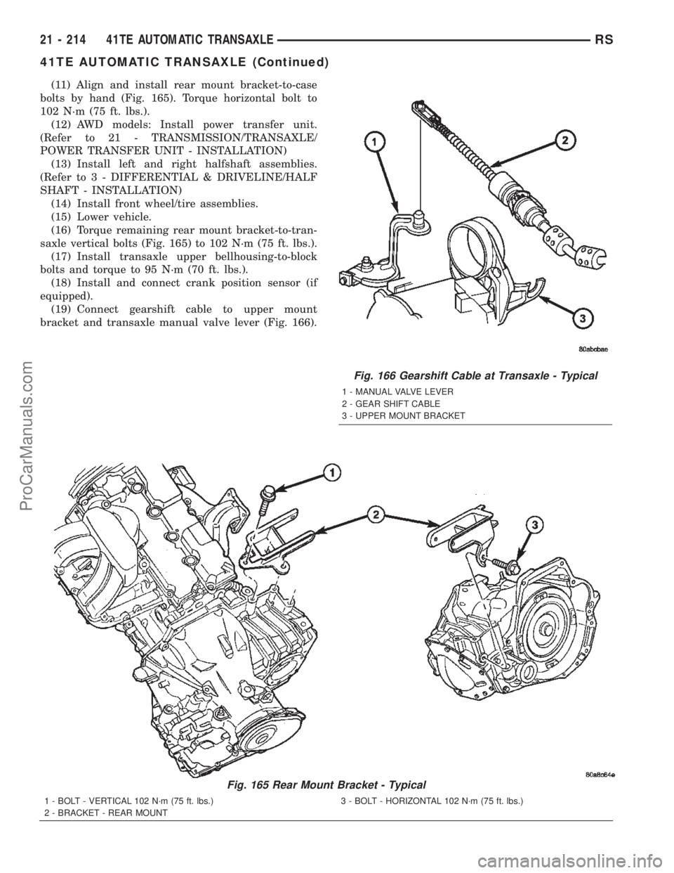
(11) Align and install rear mount bracket-to-case
bolts by hand (Fig. 165). Torque horizontal bolt to
102 N´m (75 ft. lbs.).
(12) AWD models: Install power transfer unit.
(Refer to 21 - TRANSMISSION/TRANSAXLE/
POWER TRANSFER UNIT - INSTALLATION)
(13) Install left and right halfshaft assemblies.
(Refer to 3 - DIFFERENTIAL & DRIVELINE/HALF
SHAFT - INSTALLATION)
(14) Install front wheel/tire assemblies.
(15) Lower vehicle.
(16) Torque remaining rear mount bracket-to-tran-
saxle vertical bolts (Fig. 165) to 102 N´m (75 ft. lbs.).
(17) Install transaxle upper bellhousing-to-block
bolts and torque to 95 N´m (70 ft. lbs.).
(18) Install and connect crank position sensor (if
equipped).
(19) Connect gearshift cable to upper mount
bracket and transaxle manual valve lever (Fig. 166).
Fig. 165 Rear Mount Bracket - Typical
1 - BOLT - VERTICAL 102 N´m (75 ft. lbs.)
2 - BRACKET - REAR MOUNT3 - BOLT - HORIZONTAL 102 N´m (75 ft. lbs.)
Fig. 166 Gearshift Cable at Transaxle - Typical
1 - MANUAL VALVE LEVER
2 - GEAR SHIFT CABLE
3 - UPPER MOUNT BRACKET
21 - 214 41TE AUTOMATIC TRANSAXLERS
41TE AUTOMATIC TRANSAXLE (Continued)
ProCarManuals.com
Page 1846 of 2399
OPERATION
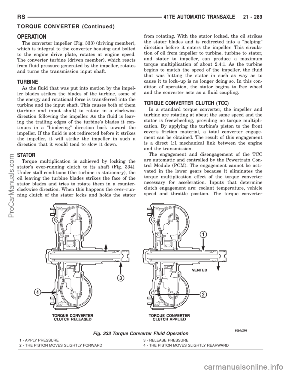
The converter impeller (Fig. 333) (driving member),
which is integral to the converter housing and bolted
to the engine drive plate, rotates at engine speed.
The converter turbine (driven member), which reacts
from fluid pressure generated by the impeller, rotates
and turns the transmission input shaft.
TURBINE
As the fluid that was put into motion by the impel-
ler blades strikes the blades of the turbine, some of
the energy and rotational force is transferred into the
turbine and the input shaft. This causes both of them
(turbine and input shaft) to rotate in a clockwise
direction following the impeller. As the fluid is leav-
ing the trailing edges of the turbine's blades it con-
tinues in a ªhinderingº direction back toward the
impeller. If the fluid is not redirected before it strikes
the impeller, it will strike the impeller in such a
direction that it would tend to slow it down.
STATOR
Torque multiplication is achieved by locking the
stator's over-running clutch to its shaft (Fig. 334).
Under stall conditions (the turbine is stationary), the
oil leaving the turbine blades strikes the face of the
stator blades and tries to rotate them in a counter-
clockwise direction. When this happens the over±run-
ning clutch of the stator locks and holds the statorfrom rotating. With the stator locked, the oil strikes
the stator blades and is redirected into a ªhelpingº
direction before it enters the impeller. This circula-
tion of oil from impeller to turbine, turbine to stator,
and stator to impeller, can produce a maximum
torque multiplication of about 2.4:1. As the turbine
begins to match the speed of the impeller, the fluid
that was hitting the stator in such as way as to
cause it to lock±up is no longer doing so. In this con-
dition of operation, the stator begins to free wheel
and the converter acts as a fluid coupling.
TORQUE CONVERTER CLUTCH (TCC)
In a standard torque converter, the impeller and
turbine are rotating at about the same speed and the
stator is freewheeling, providing no torque multipli-
cation. By applying the turbine's piston to the front
cover's friction material, a total converter engage-
ment can be obtained. The result of this engagement
is a direct 1:1 mechanical link between the engine
and the transmission.
The engagement and disengagement of the TCC
are automatic and controlled by the Powertrain Con-
trol Module (PCM). The engagement cannot be acti-
vated in the lower gears because it eliminates the
torque multiplication effect of the torque converter
necessary for acceleration. Inputs that determine
clutch engagement are: coolant temperature, vehicle
speed and throttle position. The torque converter
Fig. 333 Torque Converter Fluid Operation
1 - APPLY PRESSURE 3 - RELEASE PRESSURE
2 - THE PISTON MOVES SLIGHTLY FORWARD 4 - THE PISTON MOVES SLIGHTLY REARWARD
RS41TE AUTOMATIC TRANSAXLE21 - 289
TORQUE CONVERTER (Continued)
ProCarManuals.com
Page 1847 of 2399

clutch is engaged by the clutch solenoid on the valve
body. The clutch will engage at approximately 56
km/h (35 mph) with light throttle, after the shift to
third gear.
REMOVAL
(1) Remove transmission and torque converter
from vehicle. (Refer to 21 - TRANSMISSION/TRANS-
AXLE/AUTOMATIC - 41TE - REMOVAL)
(2) Place a suitable drain pan under the converter
housing end of the transmission.
CAUTION: Verify that transmission is secure on the
lifting device or work surface, the center of gravity
of the transmission will shift when the torque con-
verter is removed creating an unstable condition.
The torque converter is a heavy unit. Use caution
when separating the torque converter from the
transmission.
(3) Pull the torque converter forward until the cen-
ter hub clears the oil pump seal.
(4) Separate the torque converter from the trans-
mission.
INSTALLATION
Check converter hub and drive notches for sharp
edges, burrs, scratches, or nicks. Polish the hub and
notches with 320/400 grit paper or crocus cloth if nec-
essary. The hub must be smooth to avoid damaging
the pump seal at installation.
(1) Lubricate converter hub and oil pump seal lip
with transmission fluid.(2) Place torque converter in position on transmis-
sion.
CAUTION: Do not damage oil pump seal or bushing
while inserting torque converter into the front of the
transmission.
(3) Align torque converter to oil pump seal open-
ing.
(4) Insert torque converter hub into oil pump.
(5) While pushing torque converter inward, rotate
converter until converter is fully seated in the oil
pump gears.
(6) Check converter seating with a scale and
straightedge (Fig. 335). Surface of converter lugs
should be 1/2 in. to rear of straightedge when con-
verter is fully seated.
(7) If necessary, temporarily secure converter with
C-clamp attached to the converter housing.
(8) Install the transmission in the vehicle. (Refer
to 21 - TRANSMISSION/TRANSAXLE/AUTOMATIC
- 41TE - INSTALLATION)
(9) Fill the transmission with the recommended
fluid. (Refer to 21 - TRANSMISSION/TRANSAXLE/
AUTOMATIC - 41TE/FLUID - STANDARD PROCE-
DURE)
Fig. 334 Stator Operation
1 - DIRECTION STATOR WILL FREE WHEEL DUE TO OIL
PUSHING ON BACKSIDE OF VANES
2 - FRONT OF ENGINE
3 - INCREASED ANGLE AS OIL STRIKES VANES
4 - DIRECTION STATOR IS LOCKED UP DUE TO OIL PUSHING
AGAINST STATOR VANES
Fig. 335 Checking Torque Converter Seating
1 - SCALE
2 - STRAIGHTEDGE
21 - 290 41TE AUTOMATIC TRANSAXLERS
TORQUE CONVERTER (Continued)
ProCarManuals.com
Page 1898 of 2399
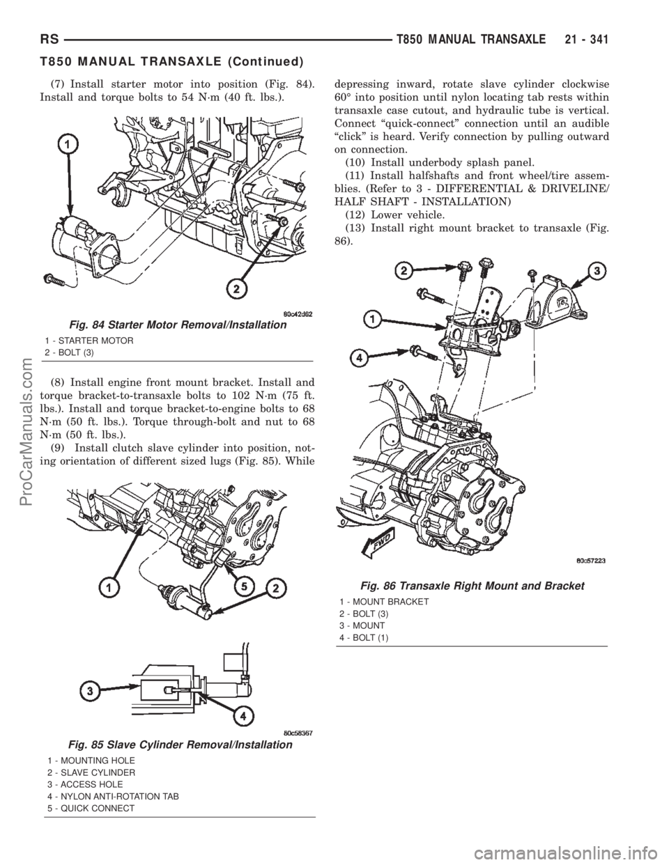
(7) Install starter motor into position (Fig. 84).
Install and torque bolts to 54 N´m (40 ft. lbs.).
(8) Install engine front mount bracket. Install and
torque bracket-to-transaxle bolts to 102 N´m (75 ft.
lbs.). Install and torque bracket-to-engine bolts to 68
N´m (50 ft. lbs.). Torque through-bolt and nut to 68
N´m (50 ft. lbs.).
(9) Install clutch slave cylinder into position, not-
ing orientation of different sized lugs (Fig. 85). Whiledepressing inward, rotate slave cylinder clockwise
60É into position until nylon locating tab rests within
transaxle case cutout, and hydraulic tube is vertical.
Connect ªquick-connectº connection until an audible
ªclickº is heard. Verify connection by pulling outward
on connection.
(10) Install underbody splash panel.
(11) Install halfshafts and front wheel/tire assem-
blies. (Refer to 3 - DIFFERENTIAL & DRIVELINE/
HALF SHAFT - INSTALLATION)
(12) Lower vehicle.
(13) Install right mount bracket to transaxle (Fig.
86).
Fig. 85 Slave Cylinder Removal/Installation
1 - MOUNTING HOLE
2 - SLAVE CYLINDER
3 - ACCESS HOLE
4 - NYLON ANTI-ROTATION TAB
5 - QUICK CONNECT
Fig. 84 Starter Motor Removal/Installation
1 - STARTER MOTOR
2 - BOLT (3)
Fig. 86 Transaxle Right Mount and Bracket
1 - MOUNT BRACKET
2 - BOLT (3)
3 - MOUNT
4 - BOLT (1)
RST850 MANUAL TRANSAXLE21 - 341
T850 MANUAL TRANSAXLE (Continued)
ProCarManuals.com
Page 1906 of 2399
BACK-UP LAMP SWITCH
REMOVAL
(1) Raise vehicle on hoist.
(2) Disconnect back-up lamp switch connector.
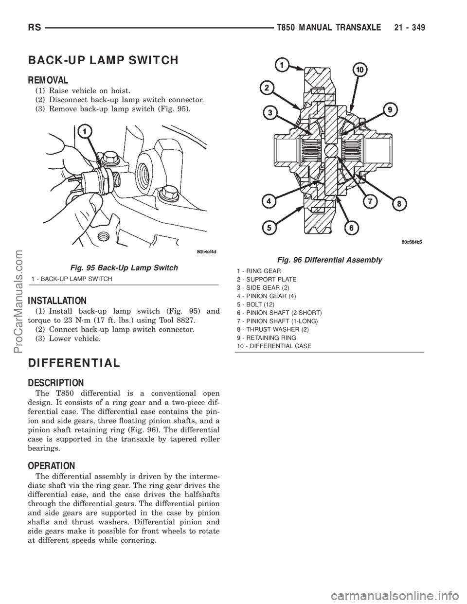
(3) Remove back-up lamp switch (Fig. 95).
INSTALLATION
(1) Install back-up lamp switch (Fig. 95) and
torque to 23 N´m (17 ft. lbs.) using Tool 8827.
(2) Connect back-up lamp switch connector.
(3) Lower vehicle.
DIFFERENTIAL
DESCRIPTION
The T850 differential is a conventional open
design. It consists of a ring gear and a two-piece dif-
ferential case. The differential case contains the pin-
ion and side gears, three floating pinion shafts, and a
pinion shaft retaining ring (Fig. 96). The differential
case is supported in the transaxle by tapered roller
bearings.
OPERATION
The differential assembly is driven by the interme-
diate shaft via the ring gear. The ring gear drives the
differential case, and the case drives the halfshafts
through the differential gears. The differential pinion
and side gears are supported in the case by pinion
shafts and thrust washers. Differential pinion and
side gears make it possible for front wheels to rotate
at different speeds while cornering.
Fig. 95 Back-Up Lamp Switch
1 - BACK-UP LAMP SWITCH
Fig. 96 Differential Assembly
1 - RING GEAR
2 - SUPPORT PLATE
3 - SIDE GEAR (2)
4 - PINION GEAR (4)
5 - BOLT (12)
6 - PINION SHAFT (2-SHORT)
7 - PINION SHAFT (1-LONG)
8 - THRUST WASHER (2)
9 - RETAINING RING
10 - DIFFERENTIAL CASE
RST850 MANUAL TRANSAXLE21 - 349
ProCarManuals.com
Page 1970 of 2399
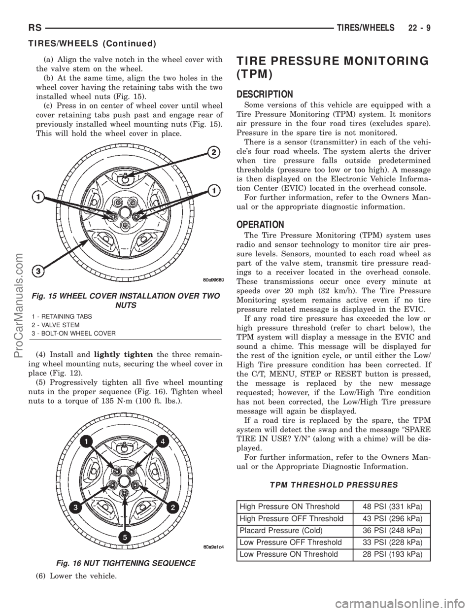
(a) Align the valve notch in the wheel cover with
the valve stem on the wheel.
(b) At the same time, align the two holes in the
wheel cover having the retaining tabs with the two
installed wheel nuts (Fig. 15).
(c) Press in on center of wheel cover until wheel
cover retaining tabs push past and engage rear of
previously installed wheel mounting nuts (Fig. 15).
This will hold the wheel cover in place.
(4) Install andlightly tightenthe three remain-
ing wheel mounting nuts, securing the wheel cover in
place (Fig. 12).
(5) Progressively tighten all five wheel mounting
nuts in the proper sequence (Fig. 16). Tighten wheel
nuts to a torque of 135 N´m (100 ft. lbs.).
(6) Lower the vehicle.TIRE PRESSURE MONITORING
(TPM)
DESCRIPTION
Some versions of this vehicle are equipped with a
Tire Pressure Monitoring (TPM) system. It monitors
air pressure in the four road tires (excludes spare).
Pressure in the spare tire is not monitored.
There is a sensor (transmitter) in each of the vehi-
cle's four road wheels. The system alerts the driver
when tire pressure falls outside predetermined
thresholds (pressure too low or too high). A message
is then displayed on the Electronic Vehicle Informa-
tion Center (EVIC) located in the overhead console.
For further information, refer to the Owners Man-
ual or the appropriate diagnostic information.
OPERATION
The Tire Pressure Monitoring (TPM) system uses
radio and sensor technology to monitor tire air pres-
sure levels. Sensors, mounted to each road wheel as
part of the valve stem, transmit tire pressure read-
ings to a receiver located in the overhead console.
These transmissions occur once every minute at
speeds over 20 mph (32 km/h). The Tire Pressure
Monitoring system remains active even if no tire
pressure related message is displayed in the EVIC.
If any road tire pressure has exceeded the low or
high pressure threshold (refer to chart below), the
TPM system will display a message in the EVIC and
sound a chime. This message will be displayed for
the rest of the ignition cycle, or until either the Low/
High Tire pressure condition has been corrected. If
the C/T, MENU, STEP or RESET button is pressed,
the message is replaced by the new message
requested; however, if the Low/High Tire condition
has not been corrected, the Low/High Tire pressure
message will again be displayed.
If a road tire is replaced by the spare, the TPM
system will detect the swap and the message9SPARE
TIRE IN USE? Y/N9(along with a chime) will be dis-
played.
For further information, refer to the Owners Man-
ual or the Appropriate Diagnostic Information.
TPM THRESHOLD PRESSURES
High Pressure ON Threshold 48 PSI (331 kPa)
High Pressure OFF Threshold 43 PSI (296 kPa)
Placard Pressure (Cold) 36 PSI (248 kPa)
Low Pressure OFF Threshold 33 PSI (228 kPa)
Low Pressure ON Threshold 28 PSI (193 kPa)
Fig. 15 WHEEL COVER INSTALLATION OVER TWO
NUTS
1 - RETAINING TABS
2 - VALVE STEM
3 - BOLT-ON WHEEL COVER
Fig. 16 NUT TIGHTENING SEQUENCE
RSTIRES/WHEELS22-9
TIRES/WHEELS (Continued)
ProCarManuals.com
Page 1971 of 2399
SENSOR - TPM
DESCRIPTION
On vehicles equipped with Tire Pressure Monitor-
ing, one tire pressure sensor is mounted to each
wheel (Fig. 19). Each sensor has an internal battery
that lasts up to 10 years. The battery is not service-
able. At the time of battery failure, the sensor must
be replaced. The serviceable components of the tire
pressure sensor are:
²Sensor-To-Wheel Grommet
²Valve Stem Cap
²Valve Stem Core
Valve stem caps and cores are specifically designed
for the tire pressure monitoring sensors. Although
similar to standard valve stem caps and cores, they
are different.
CAUTION: Do not use a standard valve stem cap or
core in a tire pressure sensor. Always use the orig-
inal equipment style sensor cap and core.
CAUTION: Do not reuse the Sensor-To Wheel Grom-
met. Always use a new grommet when installing a
pressure sensor and properly torque the sensor
nut.
CAUTION: Do not try to install a tire pressure sen-
sor in a steel wheel or aftermarket wheel. Use only
in original style factory wheels.
OPERATION
Tire pressure sensors are battery operated. They
transmit tire pressure data once every minute at
speeds above 20 mph (32 km/h) or up to once every
hour when stationary (parked). For additional infor-
mation, refer to Appropriate Diagnostic Information.
CAUTION
CAUTION: The use of tire sealants is strictly prohib-
ited for vehicles equipped with the Tire Pressure
Monitoring system. Tire sealants can clog tire pres-
sure sensors.
CAUTION: Tire pressure sensor valve stem caps
and cores are specially designed for the sensors.
Due to risk of corrosion, do not use a standard
valve stem cap or core in a tire pressure sensor in
place of the original equipment style sensor cap
and core.CAUTION: Do not attempt to install a tire pressure
sensor in a steel wheel or aftermarket wheel. Use
tire pressure sensors in original style factory
wheels only.
NOTE: TPM thresholds have been established for
the original tire size equipped on the vehicle. Use
original size tires only to maintain system accuracy.
DIAGNOSIS AND TESTING - TIRE PRESSURE
SENSOR
NOTE: Tire pressure may increase from 2 to 6 psi
(14 to 41 kPa) during normal driving conditions. Do
NOT reduce this normal pressure build up.
If a fault in the system is detected, always check
air pressure in the tires first with a known accurate
air gauge and correct the inflation pressure. If any
tire is low, inspectalltires.
If gauge-read pressure in the tires does not reflect
the reading on the EVIC, retrain the sensors, then
reevaluate (Refer to 22 - TIRES/WHEELS/TIRE
PRESSURE MONITORING/SENSOR - STANDARD
PROCEDURE). Refer to the appropriate diagnostic
information for complete diagnosis of the Tire Pres-
sure Monitoring System.
STANDARD PROCEDURE - TIRE PRESSURE
SENSOR RETRAIN
WARNING: DEATH OR SERIOUS INJURY CAN
OCCUR IF MAGNETICALLY SENSITIVE DEVICES
ARE EXPOSED TO THE RELEARN MAGNET. MAG-
NETS CAN AFFECT PACEMAKERS.
CAUTION: Never attempt to train more than one
vehicle at a time. System is capable of reading tire
pressure sensor transmissions from other near-by
vehicles.
Each time a wheel rotation or tire pressure sensor
replacement occurs the tire pressure sensors must be
retrained. This is necessary to inform the Electronic
Vehicle Information Center (EVIC) that a sensor
change was made and where. Retraining is accom-
plished through the EVIC used in conjunction with a
Re-learn Magnet, Special Tool 8821.
22 - 10 TIRES/WHEELSRS
ProCarManuals.com
Page 1972 of 2399
NOTE: Use the following procedure to retrain all
four (4) road wheel tire pressure sensors. No
attempt should be made to retrain individual sen-
sors.
(1) Retrieve Re-learn Magnet, Special Tool 8821.
(2) Press MENU Button on EVIC until9RETRAIN
TIRE SENSORS - NO9is displayed.
(3) Press STEP button to select9YES9.
NOTE: There is a 60 second timer for training the
first sensor and a 30 second timer between training
the remaining sensors. If either of these timers
expire, the EVIC will abort the training procedure.
NOTE: If at any time the EVIC display reads(TRAIN-
ING ABORTED(, move the vehicle ahead at least
one foot and repeat the entire retraining procedure.
(4) Press MENU button to start retraining. Dis-
play will read9TRAIN LEFT FRONT TIRE9
NOTE: The order for retraining all five sensors is:
²Left Front
²Right Front
²Right Rear
²Left Rear
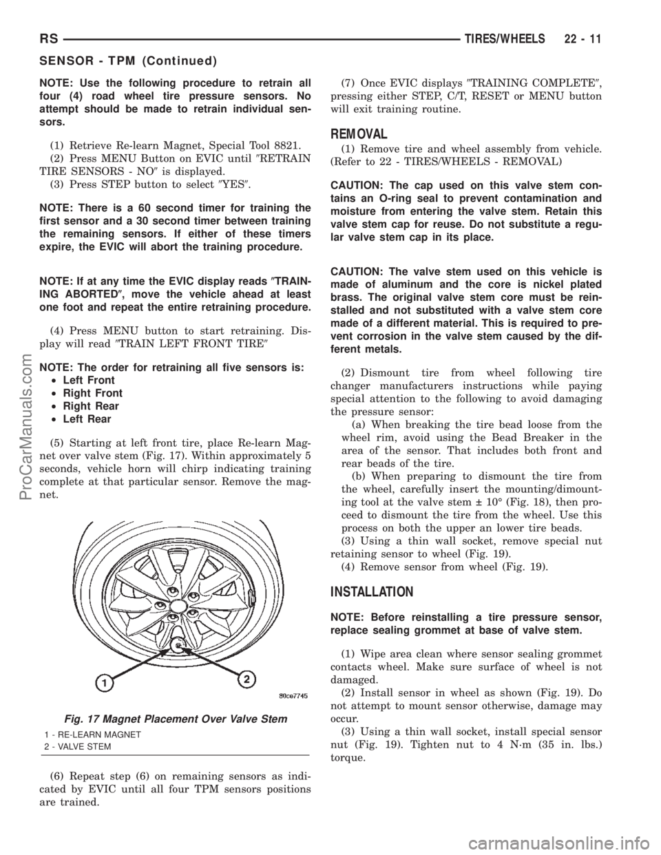
(5) Starting at left front tire, place Re-learn Mag-
net over valve stem (Fig. 17). Within approximately 5
seconds, vehicle horn will chirp indicating training
complete at that particular sensor. Remove the mag-
net.
(6) Repeat step (6) on remaining sensors as indi-
cated by EVIC until all four TPM sensors positions
are trained.(7) Once EVIC displays9TRAINING COMPLETE9,
pressing either STEP, C/T, RESET or MENU button
will exit training routine.
REMOVAL
(1) Remove tire and wheel assembly from vehicle.
(Refer to 22 - TIRES/WHEELS - REMOVAL)
CAUTION: The cap used on this valve stem con-
tains an O-ring seal to prevent contamination and
moisture from entering the valve stem. Retain this
valve stem cap for reuse. Do not substitute a regu-
lar valve stem cap in its place.
CAUTION: The valve stem used on this vehicle is
made of aluminum and the core is nickel plated
brass. The original valve stem core must be rein-
stalled and not substituted with a valve stem core
made of a different material. This is required to pre-
vent corrosion in the valve stem caused by the dif-
ferent metals.
(2) Dismount tire from wheel following tire
changer manufacturers instructions while paying
special attention to the following to avoid damaging
the pressure sensor:
(a) When breaking the tire bead loose from the
wheel rim, avoid using the Bead Breaker in the
area of the sensor. That includes both front and
rear beads of the tire.
(b) When preparing to dismount the tire from
the wheel, carefully insert the mounting/dimount-
ing tool at the valve stem 10É (Fig. 18), then pro-
ceed to dismount the tire from the wheel. Use this
process on both the upper an lower tire beads.
(3) Using a thin wall socket, remove special nut
retaining sensor to wheel (Fig. 19).
(4) Remove sensor from wheel (Fig. 19).
INSTALLATION
NOTE: Before reinstalling a tire pressure sensor,
replace sealing grommet at base of valve stem.
(1) Wipe area clean where sensor sealing grommet
contacts wheel. Make sure surface of wheel is not
damaged.
(2) Install sensor in wheel as shown (Fig. 19). Do
not attempt to mount sensor otherwise, damage may
occur.
(3) Using a thin wall socket, install special sensor
nut (Fig. 19). Tighten nut to 4 N´m (35 in. lbs.)
torque.
Fig. 17 Magnet Placement Over Valve Stem
1 - RE-LEARN MAGNET
2 - VALVE STEM
RSTIRES/WHEELS22-11
SENSOR - TPM (Continued)
ProCarManuals.com
Page 1978 of 2399
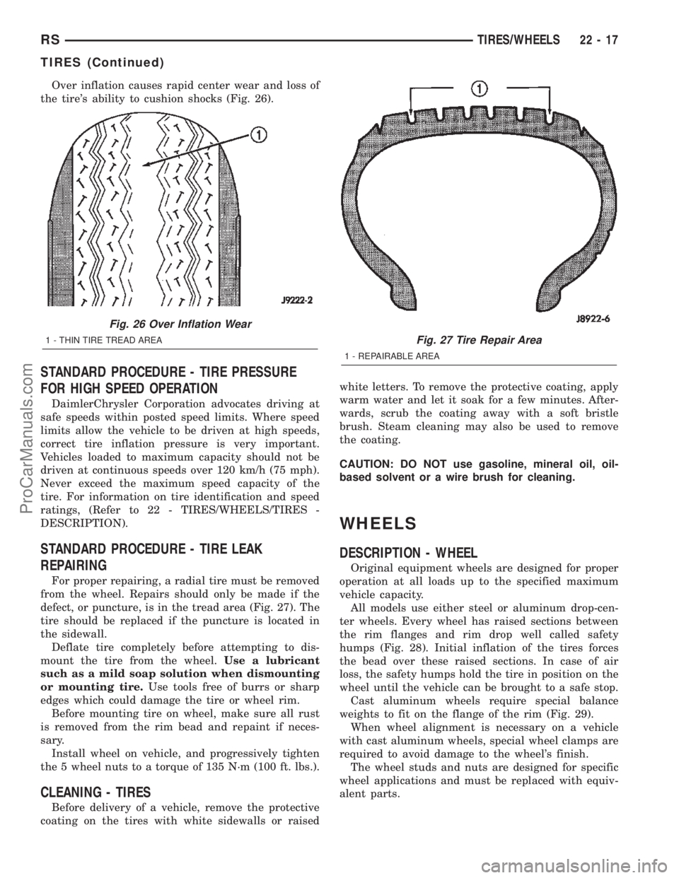
Over inflation causes rapid center wear and loss of
the tire's ability to cushion shocks (Fig. 26).
STANDARD PROCEDURE - TIRE PRESSURE
FOR HIGH SPEED OPERATION
DaimlerChrysler Corporation advocates driving at
safe speeds within posted speed limits. Where speed
limits allow the vehicle to be driven at high speeds,
correct tire inflation pressure is very important.
Vehicles loaded to maximum capacity should not be
driven at continuous speeds over 120 km/h (75 mph).
Never exceed the maximum speed capacity of the
tire. For information on tire identification and speed
ratings, (Refer to 22 - TIRES/WHEELS/TIRES -
DESCRIPTION).
STANDARD PROCEDURE - TIRE LEAK
REPAIRING
For proper repairing, a radial tire must be removed
from the wheel. Repairs should only be made if the
defect, or puncture, is in the tread area (Fig. 27). The
tire should be replaced if the puncture is located in
the sidewall.
Deflate tire completely before attempting to dis-
mount the tire from the wheel.Use a lubricant
such as a mild soap solution when dismounting
or mounting tire.Use tools free of burrs or sharp
edges which could damage the tire or wheel rim.
Before mounting tire on wheel, make sure all rust
is removed from the rim bead and repaint if neces-
sary.
Install wheel on vehicle, and progressively tighten
the 5 wheel nuts to a torque of 135 N´m (100 ft. lbs.).
CLEANING - TIRES
Before delivery of a vehicle, remove the protective
coating on the tires with white sidewalls or raisedwhite letters. To remove the protective coating, apply
warm water and let it soak for a few minutes. After-
wards, scrub the coating away with a soft bristle
brush. Steam cleaning may also be used to remove
the coating.
CAUTION: DO NOT use gasoline, mineral oil, oil-
based solvent or a wire brush for cleaning.
WHEELS
DESCRIPTION - WHEEL
Original equipment wheels are designed for proper
operation at all loads up to the specified maximum
vehicle capacity.
All models use either steel or aluminum drop-cen-
ter wheels. Every wheel has raised sections between
the rim flanges and rim drop well called safety
humps (Fig. 28). Initial inflation of the tires forces
the bead over these raised sections. In case of air
loss, the safety humps hold the tire in position on the
wheel until the vehicle can be brought to a safe stop.
Cast aluminum wheels require special balance
weights to fit on the flange of the rim (Fig. 29).
When wheel alignment is necessary on a vehicle
with cast aluminum wheels, special wheel clamps are
required to avoid damage to the wheel's finish.
The wheel studs and nuts are designed for specific
wheel applications and must be replaced with equiv-
alent parts.
Fig. 26 Over Inflation Wear
1 - THIN TIRE TREAD AREAFig. 27 Tire Repair Area
1 - REPAIRABLE AREA
RSTIRES/WHEELS22-17
TIRES (Continued)
ProCarManuals.com
Page 1980 of 2399
SPECIFICATIONS
WHEEL
SPECIFICATIONS
DESCRIPTION SPECIFICATION
Wheel Mounting (Lug)
Nut Hex Size19 mm
Wheel Mounting Stud
SizeM12 x 1.5 mm
TORQUE SPECIFICATIONS
DESCRIPTION N´mFt.
Lbs.In.
Lbs.
Wheel Mounting (Lug ) Nut 135 100 Ð
WHEEL COVER
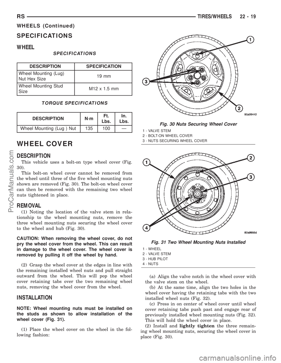
DESCRIPTION
This vehicle uses a bolt-on type wheel cover (Fig.
30).
This bolt-on wheel cover cannot be removed from
the wheel until three of the five wheel mounting nuts
shown are removed (Fig. 30). The bolt-on wheel cover
can then be removed with the remaining two wheel
nuts tightened in place.
REMOVAL
(1) Noting the location of the valve stem in rela-
tionship to the wheel mounting nuts, remove the
three wheel mounting nuts securing the wheel cover
to the wheel and hub (Fig. 30).
CAUTION: When removing the wheel cover, do not
pry the wheel cover from the wheel. This can result
in damage to the wheel cover. The wheel cover is
removed by pulling it off the wheel by hand.
(2) Grasp the wheel cover at the edges in line with
the remaining installed wheel nuts and pull straight
outward from the wheel. This will pop the wheel
cover retaining tabs over the two remaining wheel
nuts, removing the wheel cover from the wheel.
INSTALLATION
NOTE: Wheel mounting nuts must be installed on
the studs as shown to allow installation of the
wheel cover (Fig. 31).
(1) Place the wheel cover on the wheel in the fol-
lowing fashion:(a) Align the valve notch in the wheel cover with
the valve stem on the wheel.
(b) At the same time, align the two holes in the
wheel cover having the retaining tabs with the two
installed wheel nuts (Fig. 32).
(c) Press in on center of wheel cover until wheel
cover retaining tabs push past and engage rear of
previously installed wheel mounting nuts (Fig. 32).
This will hold the wheel cover in place.
(2) Install andlightly tightenthe three remain-
ing wheel mounting nuts, securing the wheel cover in
place (Fig. 30).
Fig. 30 Nuts Securing Wheel Cover
1 - VALVE STEM
2 - BOLT-ON WHEEL COVER
3 - NUTS SECURING WHEEL COVER
Fig. 31 Two Wheel Mounting Nuts Installed
1 - WHEEL
2 - VALVE STEM
3 - HUB PILOT
4 - NUTS
RSTIRES/WHEELS22-19
WHEELS (Continued)
ProCarManuals.com