HVAC CHRYSLER VOYAGER 2002 User Guide
[x] Cancel search | Manufacturer: CHRYSLER, Model Year: 2002, Model line: VOYAGER, Model: CHRYSLER VOYAGER 2002Pages: 2399, PDF Size: 57.96 MB
Page 613 of 2399
When the front airbag system is deployed, the fol-
lowingMUSTbe replaced:
²Complete Steering Column Assembly.
²Lower Steering Column Coupler.
²Steering Wheel.
²Clock Spring.
²Driver Airbag
²Passenger Airbag
²Upper Instrument Panel with Pad.
CARE OF UNDEPLOYED AIRBAGS
Airbags must be stored in their original special
container until used for service. At no time should a
source of electricity be permitted near the inflator on
the back of an airbag. When carrying or handling an
undeployed airbag, the trim side of the airbag should
be pointing away from the body to minimize possibil-
ity of injury if accidental deployment occurs. Do not
place undeployed airbag face down on a solid surface,
the airbag will propel into the air if accidental
deployment occurs.
STANDARD PROCEDURE - CLEAN UP
Roll or fold the driver airbag towards the steering
wheel and then tape the bag to the steering wheel.
Use a vacuum cleaner to remove any residual pow-
der from the vehicle interior. Work from the outside
in to avoid kneeling or sitting in a contaminated
area. Vacuum the heater and A/C outlets as well. If
HVAC was in RECIRC mode at time of airbag
deployment, operate HVAC blower on low speed/heat
and vacuum powder residue expelled from the heat
outlets. Multiple vacuum cleaning may be necessary
to decontaminate the interior of the vehicle.
REMOVAL
DEPLOYED AIRBAG
The Driver Airbag and Driver Airbag Cover/Horn
Pad are serviced separately from each other.
(1) Clean powder residue from interior of vehicle,
(Refer to 8 - ELECTRICAL/RESTRAINTS/DRIVER
AIRBAG - STANDARD PROCEDURE ) Cleanup.
(2) Remove two screws attaching Driver Airbag to
steering wheel.
(3) Remove the driver airbag from steering wheel.
(4) Disconnect wire connectors from Airbag and
Clock Spring.
(5) Adjust the steering wheel so that the tires are
in a straight ahead position. Remove steering wheel,
(Refer to 19 - STEERING/COLUMN/STEERING
WHEEL - REMOVAL)
(6) Disconnect the 2-way and 4-way connectors
between the clock spring and the instrument panel
wiring harness.(7) Remove upper and lower steering column
shrouds.
(8) Remove clock spring from the housing assem-
bly by depressing the 2 tabs on the clock spring.
UNDEPLOYED AIRBAG
(1) Remove screws attaching airbag/horn switch to
steering wheel.
(2) Remove Driver Airbag from steering wheel.
(3) Disconnect wire connectors from driver airbag
and clock spring.
INSTALLATION
DEPLOYED AIRBAG
(1) Perform cleanup procedure.(Refer to 8 - ELEC-
TRICAL/RESTRAINTS/DRIVER AIRBAG - STAN-
DARD PROCEDURE)
(2) Install a new steering column assembly and
lower steering column coupler. Refer to Steering, Col-
umn, Installation.
(3) Install the clock spring.
(4) Install the driver airbag and the two screws
retaining the airbag. Tighten screws to 10 N´m (90
in. lbs.)
WARNING: DO NOT CONNECT THE BATTERY NEG-
ATIVE CABLE. REFER TO ELECTRICAL,
RESTRAINTS, DIAGNOSIS AND TESTING - AIRBAG
SYSTEM FIRST.
UNDEPLOYED AIRBAG
(1) Position a new airbag into the airbag cavity.
(2) Install the two screws retaining the airbag.
Tighten screws to 10 N´m (90 in. lbs.)
WARNING: DO NOT CONNECT THE BATTERY NEG-
ATIVE CABLE. REFER TO ELECTRICAL,
RESTRAINTS, DIAGNOSIS AND TESTING - AIRBAG
SYSTEM FIRST.
DRIVER AIRBAG TRIM COVER
REMOVAL
The horn switch is integral to the driver airbag
trim cover. If either component is faulty or damaged,
the entire driver airbag trim cover and horn switch
unit must be replaced.
(1) Disconnect and isolate the battery negative
cable.
WARNING: WAIT TWO MINUTES FOR THE AIRBAG
SYSTEM RESERVE CAPACITOR TO DISCHARGE.
8O - 4 RESTRAINTSRS
DRIVER AIRBAG (Continued)
ProCarManuals.com
Page 615 of 2399
PASSENGER AIRBAG
DESCRIPTION
WARNING: NEVER DISASSEMBLE THE PASSEN-
GER AIRBAG, THE PASSENGER AIRBAG HAS NO
SERVICEABLE PARTS.
The Passenger Airbag is located beneath the
instrument panel and pad assembly. The airbag is
mounted to the back side of the instrument panel
reinforcement.
The instrument panel top pad is the most visible
part of the passenger airbag system. Located under
the instrument panel top pad are the airbag door, the
passenger airbag cushion and the airbag cushion
supporting components.
The passenger airbag includes a magnesium hous-
ing within which the cushion and inflator are
mounted and sealed.
Following a passenger airbag deployment, the pas-
senger airbag and the instrument panel must be
replaced. The passenger airbag cannot be repaired,
and must be replaced if deployed or damaged in any
way.
OPERATION
The passenger airbag is equipped with two infla-
tors, each with three levels of pressure output. The
inflators seal the hole in the airbag cushion so it can
discharge the gas it produces directly into the cush-
ion when supplied with the proper electrical signal.
Following an airbag deployment, the airbag cushion
quickly deflates by venting this gas through the
cushion material towards the instrument panel.
The passenger airbag is secured with screws to the
instrument panel beneath the instrument panel top
pad and above the glove box opening. The instrument
panel top pad above the glove box opening conceals
the airbag door and a predetermined hinge line
beneath its decorative cover. Upon airbag deploy-
ment, the top pad will bend at the hinge line and the
door will fold back out of the way onto the top of the
instrument panel.
When the front airbag system is deployed, the fol-
lowingMUSTbe replaced:
²Complete Steering Column Assembly.
²Lower Steering Column Coupler.
²Steering Wheel.
²Clock Spring.
²Driver Airbag.
²Passenger Airbag.
²Upper Instrument Panel with Pad.
CARE OF UNDEPLOYED AIRBAGS
Airbags must be stored in their original special
container until used for service. At no time should a
source of electricity be permitted near the inflator on
the back of an airbag. When carrying or handling an
undeployed airbag, the trim side of the airbag should
be pointing away from the body to minimize possibil-
ity of injury if accidental deployment occurs. Do not
place undeployed airbag face down on a solid surface,
the airbag will propel into the air if accidental
deployment occurs.
STANDARD PROCEDURE - CLEAN UP
Roll or fold the passenger airbag towards the
instrument panel surface and close the door over the
folded bag. Then tape the door shut.
Use a vacuum cleaner to remove any residual pow-
der from the vehicle interior. Work from the outside
in to avoid kneeling or sitting in a contaminated
area. Vacuum the heater and A/C outlets as well. If
HVAC was in RECIRC mode at time of airbag
deployment, operate HVAC blower on low speed/heat
and vacuum powder residue expelled from the heat
outlets. Multiple vacuum cleaning may be necessary
to decontaminate the interior of the vehicle.
REMOVAL
DEPLOYED AIRBAG
(1) Clean powder residue from interior of vehicle.
Refer to Electrical, Restraints, Passenger Airbag,
Standard Procedure - Passenger Airbag Clean Up.
(2) Remove instrument panel. Refer to Body,
Instrument Panel, Removal.
(3) Remove all reusable components from the
upper instrument panel and transfer to the new
instrument panel.
UNDEPLOYED AIRBAG
(1) Remove instrument panel. Refer to Body,
Instrument Panel, Removal.
(2) De-trim the instrument panel enough to gain
access to the passenger airbag fasteners.
(3) Disconnect yellow wire connector from passen-
ger airbag.
(4) Remove three bolts to the passenger airbag.
(5) Remove airbag from instrument panel through
rear of instrument panel.
INSTALLATION
DEPLOYED AIRBAG
Transfer all reusable components to the new
instrument panel.
(1) Install new Passenger Airbag into instrument
panel.
8O - 6 RESTRAINTSRS
ProCarManuals.com
Page 620 of 2399

(13) Install second row seat to vehicle. Refer to
Owner's Manual for proper procedures.
SEAT BELT SECOND RIGHT
ROW OUTBOARD - LBW WITH
REAR HVAC
REMOVAL
(1) Remove second row seat from vehicle. Refer to
Owner's Manual for proper procedures.
(2) Slide lower anchor cover from over the anchor
shoulder-nut.
(3) Remove lower anchor shoulder-nut.
(4) Remove lower anchor from wheelhouse.
(5) Fold upper turning loop extension cover down-
ward to gain access to anchor bolt.
(6) Remove bolt attaching turning loop to exten-
sion bracket above quarter glass.
(7) Remove turning loop from extension bracket.
(8) Remove D-pillar trim panel.
(9) Remove quarter trim bolster.(10) Remove quarter trim panel as necessary to
gain access to HVAC unit.
(11) Route seat belt webbing and turning loop
through access hole in quarter trim.
(12) Loosen HVAC unit enough to gain access to
seat belt retractor fasteners.
(a) Remove bracket around HVAC unit (Fig. 6).
(b) Remove air duct (Fig. 7).
(c) Remove fasteners attaching HVAC unit to
inner quarter panel (Fig. 8).
(d) Remove screws attaching upper evaporator
housing to lower evaporator housing.
(e) Remove coolant line retaining bracket hold
down bolt.
(13) Remove bolts attaching seat belt guide loop to
inner quarter panel.
(14) Pull outward on HVAC unit and remove bolt
attaching retractor to inner quarter panel.
(15) Remove screw attaching retractor to inner
quarter panel.
(16) Remove second row seat belt retractor from
vehicle.INSTALLATION
(1) Position second row seat belt retractor to vehi-
cle.
(2) Install screw attaching retractor to inner quar-
ter panel.
(3) Pull outward on HVAC unit and install bolt
attaching retractor to inner quarter panel. Tighten-
ing specifications for all seat belt bolts is 39 N´m (29
ft. lbs.) torque.
(4) Install bolts attaching seat belt guide loop to
inner quarter panel.
(5) Install coolant line retaining bracket hold down
bolt.
Fig. 5 SECOND RIGHT ROW OUTBOARD SEAT
BELT - LWB
1 - TURNING LOOP GUIDE
2 - RETRACTOR 2nd REAR
3 - LOWER QUARTER TRIM
4 - LOWER ANCHOR
5 - RETRACTOR 1st REAR
6 - ANCHOR BRACKET
7 - QUARTER PANEL
8 - C-PILLAR TRIM
9 - HEIGHT ADJUSTER
Fig. 6 TRIM PANEL MOUNTING BRACKET
1 - TRIM PANEL MOUNTING BRACKET
RSRESTRAINTS8O-11
SEAT BELT SECOND RIGHT ROW OUTBOARD - LWB (Continued)
ProCarManuals.com
Page 621 of 2399

(6) Install screws attaching upper evaporator
housing to lower evaporator housing.
(7) Install fasteners attaching HVAC unit to inner
quarter panel.
(8) Install air duct.
(9) Install bracket around HVAC unit.
(10) Route seat belt webbing and turning loop
through access hole in quarter trim.
(11) Install quarter trim panel as necessary to gain
access to HVAC unit.
(12) Install quarter trim bolster.(13) Install D-pillar trim panel.
(14) Position turning loop to extension bracket.
(15) Install bolt attaching turning loop to exten-
sion bracket above quarter glass. Tightening seat belt
bolt to 39 N´m (29 ft. lbs.) torque.
(16) Pull upper turning loop extension cover
upward over anchor bolt.
(17) Install lower anchor shoulder-nut. Tightening
seat belt bolt to 39 N´m (29 ft. lbs.) torque.
(18) Slide lower anchor cover over anchor shoul-
der-nut.
(19) Install second row seat from vehicle. Refer to
Owner's Manual for proper procedures.
SEAT BELT SECOND ROW
OUTBOARD - SWB
REMOVAL
(1) Remove second row seat from vehicle. Refer to
Owner's Manual for proper procedures.
(2) Slide lower anchor cover from over the anchor
shoulder-nut.
(3) Remove lower anchor shoulder-nut.
(4) Remove lower anchor from wheelhouse (Fig. 9).
(5) Remove D-pillar trim panel.
(6) Route seat belt webbing and turning loop
through access hole in quarter trim.
(7) Remove bolts attaching seat belt guide loop to
inner quarter panel.
(8) Remove anchor bolt attaching retractor to
inner quarter panel.
(9) Remove second row seat belt retractor from
vehicle (Fig. 9).
INSTALLATION
(1) Place second row seat belt retractor into posi-
tion.
(2) Install anchor bolt attaching retractor to inner
quarter panel. Tighten all seat belts to 39 N´m (29 ft.
lbs.) torque.
(3) Install bolts attaching seat belt guide loop to
inner quarter panel.
(4) Route seat belt webbing and turning loop
through access hole in quarter trim.
(5) Install D-pillar trim panel.
(6) Install lower anchor to the wheelhouse.
(7) Install lower anchor shoulder-nut. Tighten all
seat belts to 39 N´m (29 ft. lbs.) torque.
(8) Slide lower anchor cover over the anchor shoul-
der-nut.
Fig. 7 LOWER HEATER DUCT
1 - LOWER HEAT DUCT MOUNTING
Fig. 8 REAR HVAC MOUNTING
1 - REAR HVAC MODULE MOUNTING
2 - REAR EVAPORATOR LOWER HOUSING
3 - REAR EVAPORATOR UPPER HOUSING
8O - 12 RESTRAINTSRS
SEAT BELT SECOND RIGHT ROW OUTBOARD - LBW WITH REAR HVAC (Continued)
ProCarManuals.com
Page 653 of 2399
REAR WIPER MOTOR
REMOVAL
(1) Disconnect and isolate the battery negative
cable.
(2) Remove rear wiper arm. (Refer to 8 - ELEC-
TRICAL/WIPERS/WASHERS/REAR WIPER ARM -
REMOVAL) in this section.
(3) Open liftgate.
(4) Remove liftgate trim panel. (Refer to 23 -
BODY/DECKLID/HATCH/LIFTGATE/TAILGATE/
TRIM PANEL - REMOVAL).
(5) Disconnect wire connector from rear wiper
motor.
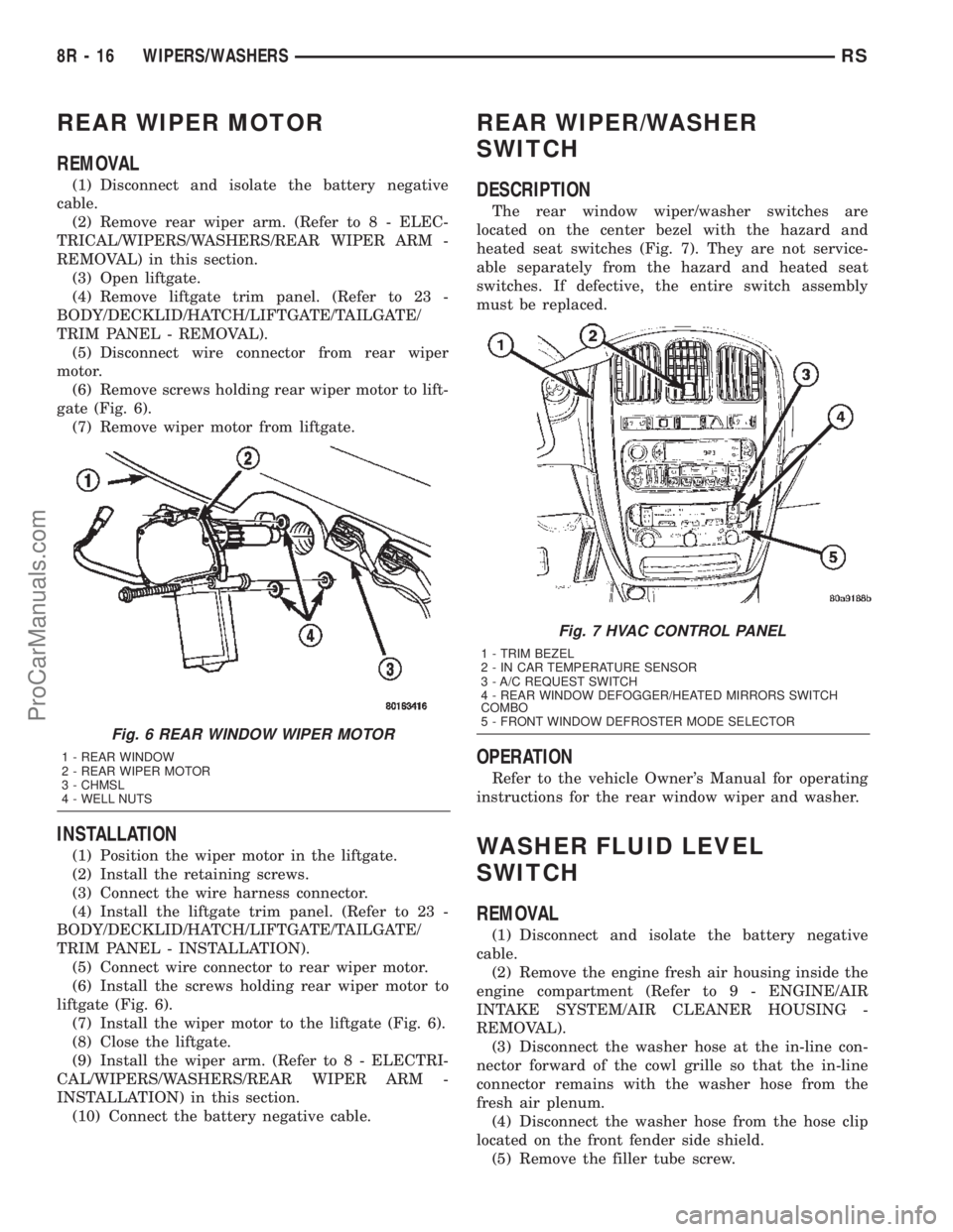
(6) Remove screws holding rear wiper motor to lift-
gate (Fig. 6).
(7) Remove wiper motor from liftgate.
INSTALLATION
(1) Position the wiper motor in the liftgate.
(2) Install the retaining screws.
(3) Connect the wire harness connector.
(4) Install the liftgate trim panel. (Refer to 23 -
BODY/DECKLID/HATCH/LIFTGATE/TAILGATE/
TRIM PANEL - INSTALLATION).
(5) Connect wire connector to rear wiper motor.
(6) Install the screws holding rear wiper motor to
liftgate (Fig. 6).
(7) Install the wiper motor to the liftgate (Fig. 6).
(8) Close the liftgate.
(9) Install the wiper arm. (Refer to 8 - ELECTRI-
CAL/WIPERS/WASHERS/REAR WIPER ARM -
INSTALLATION) in this section.
(10) Connect the battery negative cable.
REAR WIPER/WASHER
SWITCH
DESCRIPTION
The rear window wiper/washer switches are
located on the center bezel with the hazard and
heated seat switches (Fig. 7). They are not service-
able separately from the hazard and heated seat
switches. If defective, the entire switch assembly
must be replaced.
OPERATION
Refer to the vehicle Owner's Manual for operating
instructions for the rear window wiper and washer.
WASHER FLUID LEVEL
SWITCH
REMOVAL
(1) Disconnect and isolate the battery negative
cable.
(2) Remove the engine fresh air housing inside the
engine compartment (Refer to 9 - ENGINE/AIR
INTAKE SYSTEM/AIR CLEANER HOUSING -
REMOVAL).
(3) Disconnect the washer hose at the in-line con-
nector forward of the cowl grille so that the in-line
connector remains with the washer hose from the
fresh air plenum.
(4) Disconnect the washer hose from the hose clip
located on the front fender side shield.
(5) Remove the filler tube screw.
Fig. 6 REAR WINDOW WIPER MOTOR
1 - REAR WINDOW
2 - REAR WIPER MOTOR
3 - CHMSL
4 - WELL NUTS
Fig. 7 HVAC CONTROL PANEL
1 - TRIM BEZEL
2 - IN CAR TEMPERATURE SENSOR
3 - A/C REQUEST SWITCH
4 - REAR WINDOW DEFOGGER/HEATED MIRRORS SWITCH
COMBO
5 - FRONT WINDOW DEFROSTER MODE SELECTOR
8R - 16 WIPERS/WASHERSRS
ProCarManuals.com
Page 1035 of 2399

Component Page
Memory Set Switch.................. 8W-80-84
Message Center (High Line)........... 8W-80-85
Mode Door Actuator (ATC)............ 8W-80-85
Mode Door Actuator (MTC)............ 8W-80-85
Multi-Function Switch............... 8W-80-85
Output Speed Sensor (EATX).......... 8W-80-86
Overhead Console (Except Base)........ 8W-80-86
Oxygen Sensor 1/1 Upstream (Gas)...... 8W-80-86
Oxygen Sensor 1/2 Downstream (Gas) . . . 8W-80-87
Park/Neutral Position Switch (ATX)..... 8W-80-87
Passenger Airbag................... 8W-80-87
Passenger Blend Door Actuator (ATC) . . . 8W-80-87
Passenger Blend Door Actuator (MTC) . . . 8W-80-87
Passenger Door Courtesy Lamp........ 8W-80-88
Passenger Door Lock Switch........... 8W-80-88
Passenger Folding Mirror Relay
(Built-Up-Export)................. 8W-80-88
Passenger Heated Seat Back........... 8W-80-88
Passenger Heated Seat Cushion........ 8W-80-88
Passenger Heated Seat Module C1...... 8W-80-89
Passenger Heated Seat Module C2...... 8W-80-89
Passenger Heated Seat Module C3...... 8W-80-89
Passenger Power Seat Front Riser Motor . 8W-80-89
Passenger Power Seat Horizontal Motor . . 8W-80-90
Passenger Power Seat Rear Riser Motor . . 8W-80-90
Passenger Power Seat Recliner Motor.... 8W-80-90
Passenger Power Seat Switch.......... 8W-80-90
Passenger Power Window Motor........ 8W-80-90
Passenger Power Window Switch....... 8W-80-91
Passenger Seat Belt Switch........... 8W-80-91
Passenger Seat Belt Tensioner......... 8W-80-91
Power Folding Mirror Switch
(Built-Up-Export)................. 8W-80-91
Power Liftgate Module C1............ 8W-80-92
Power Liftgate Module C2............ 8W-80-92
Power Liftgate Motor................ 8W-80-92
Power Mirror Switch................. 8W-80-93
Power Outlet....................... 8W-80-93
Power Seat Circuit Breaker (30A)....... 8W-80-93
Power Window Circuit Breaker (25A).... 8W-80-93
Power Window Switch (Lowline)........ 8W-80-94
Powertrain Control Module C1 (Gas).... 8W-80-94
Powertrain Control Module C2 (Gas).... 8W-80-95
Radiator Fan No. 1 (Diesel)........... 8W-80-96
Radiator Fan No. 1 (Gas)............. 8W-80-96
Radiator Fan No. 2 (Diesel)........... 8W-80-96
Radiator Fan No. 2 (Gas)............. 8W-80-96
Radiator Fan Relay (Gas)............. 8W-80-96
Radiator Fan Relay No. 1 (Diesel)....... 8W-80-97
Radiator Fan Relay No. 2 (Diesel)....... 8W-80-97
Radiator Fan Relay No. 3 (Diesel)....... 8W-80-97
Radio C1.......................... 8W-80-98
Radio C2.......................... 8W-80-98
Radio Choke....................... 8W-80-99Component Page
Rear A/C-Heater Unit (3 Zone HVAC).... 8W-80-99
Rear Auto Temp Control Switch (ATC) . . . 8W-80-99
Rear Blower Front Control Switch
(3 Zone HVAC)................... 8W-80-99
Rear Blower Motor Power Module
C1(ATC) ....................... 8W-80-100
Rear Blower Motor Power Module C2
(ATC).......................... 8W-80-100
Rear Blower Rear Control Switch C1
(3 Zone HVAC).................. 8W-80-100
Rear Blower Rear Control Switch C2
(3 Zone HVAC).................. 8W-80-100
Rear Dome Lamp (Except Luxury)..... 8W-80-100
Rear Mode Motor (ATC)............. 8W-80-101
Rear Power Outlet................. 8W-80-101
Rear Temperature Motor (ATC)........ 8W-80-101
Rear Washer Pump Motor............ 8W-80-101
Rear Wiper Motor.................. 8W-80-101
Recirculation Door Actuator (ATC)..... 8W-80-102
Recirculation Door Actuator (MTC)..... 8W-80-102
Remote Keyless Entry Antenna
(Japan)........................ 8W-80-102
Remote Keyless Entry Module........ 8W-80-102
Right B-Pillar Switch
(Power Sliding Door).............. 8W-80-102
Right Cinch/Release Motor
(Power Sliding Door).............. 8W-80-103
Right Combination Relay (Trailer Tow) . . 8W-80-103
Right Cylinder Lock Switch.......... 8W-80-103
Right Door Speaker................. 8W-80-103
Right Fog Lamp (Built-Up-Export)..... 8W-80-103
Right Fog Lamp (Except
Built-Up-Export)................. 8W-80-104
Right Front Door Ajar Switch (Base).... 8W-80-104
Right Front Door Lock Motor/Ajar
Switch (Except Base).............. 8W-80-104
Right Front Park/Turn Signal Lamp
(Except Built-Up-Export).......... 8W-80-104
Right Front Wheel Speed Sensor...... 8W-80-104
Right Full Open Switch
(Power Sliding Door).............. 8W-80-105
Right Headlamp (Except
Built-Up-Export)................. 8W-80-105
Right Headlamp Leveling Motor
(Built-Up-Export)................ 8W-80-105
Right High Beam Lamp
(Built-Up-Export)................ 8W-80-105
Right Instrument Panel Speaker...... 8W-80-105
Right Liftgate Flood Lamp........... 8W-80-106
Right Low Beam Lamp
(Built-Up-Export)................ 8W-80-106
Right Mid Reading Lamp
(Premium/Luxury)................ 8W-80-106
Right Park Lamp (Built-Up-Export).... 8W-80-106
Right Power Mirror................. 8W-80-106
8W - 80 - 4 8W-80 CONNECTOR PIN-OUTSRS
ProCarManuals.com
Page 1037 of 2399
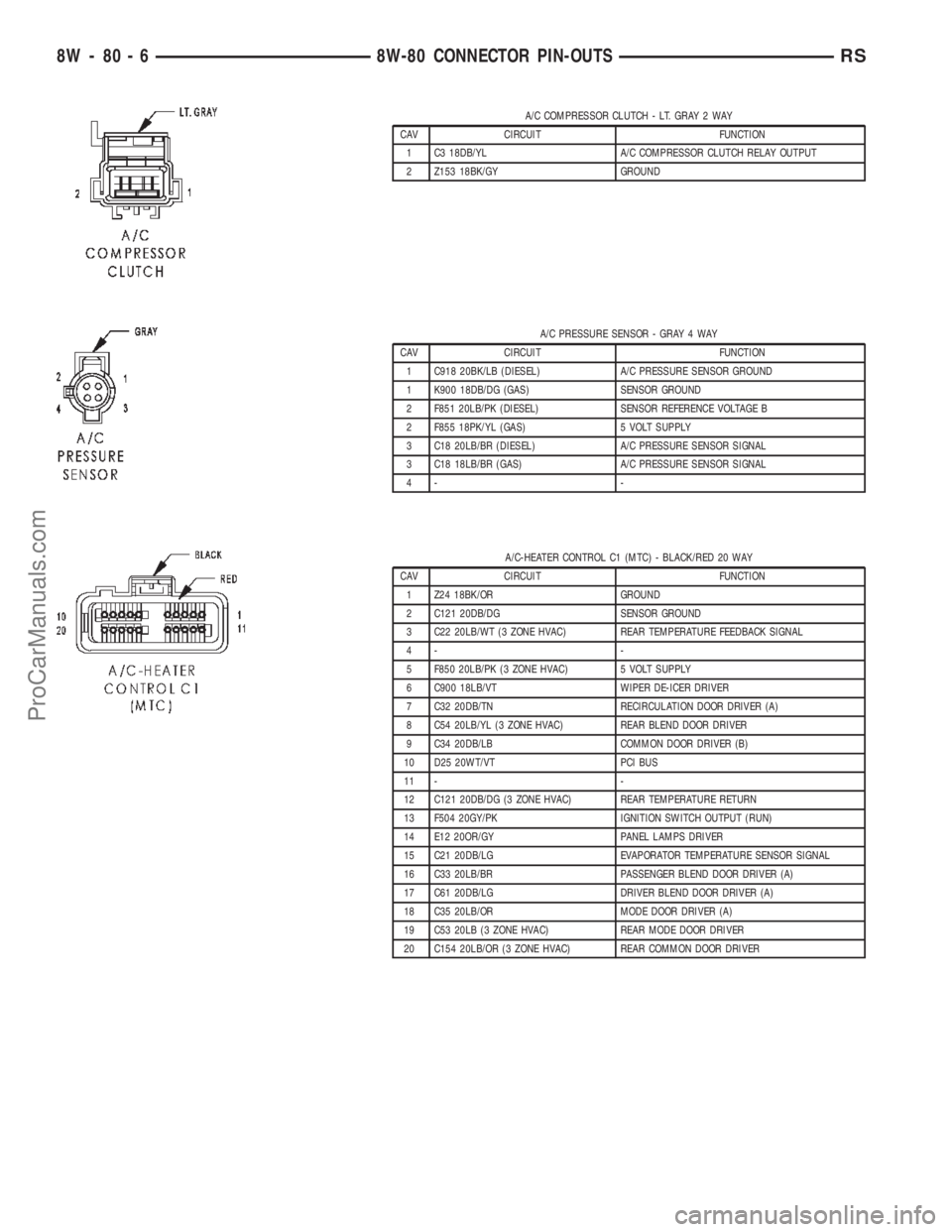
A/C COMPRESSOR CLUTCH - LT. GRAY 2 WAY
CAV CIRCUIT FUNCTION
1 C3 18DB/YL A/C COMPRESSOR CLUTCH RELAY OUTPUT
2 Z153 18BK/GY GROUND
A/C PRESSURE SENSOR - GRAY 4 WAY
CAV CIRCUIT FUNCTION
1 C918 20BK/LB (DIESEL) A/C PRESSURE SENSOR GROUND
1 K900 18DB/DG (GAS) SENSOR GROUND
2 F851 20LB/PK (DIESEL) SENSOR REFERENCE VOLTAGE B
2 F855 18PK/YL (GAS) 5 VOLT SUPPLY
3 C18 20LB/BR (DIESEL) A/C PRESSURE SENSOR SIGNAL
3 C18 18LB/BR (GAS) A/C PRESSURE SENSOR SIGNAL
4- -
A/C-HEATER CONTROL C1 (MTC) - BLACK/RED 20 WAY
CAV CIRCUIT FUNCTION
1 Z24 18BK/OR GROUND
2 C121 20DB/DG SENSOR GROUND
3 C22 20LB/WT (3 ZONE HVAC) REAR TEMPERATURE FEEDBACK SIGNAL
4- -
5 F850 20LB/PK (3 ZONE HVAC) 5 VOLT SUPPLY
6 C900 18LB/VT WIPER DE-ICER DRIVER
7 C32 20DB/TN RECIRCULATION DOOR DRIVER (A)
8 C54 20LB/YL (3 ZONE HVAC) REAR BLEND DOOR DRIVER
9 C34 20DB/LB COMMON DOOR DRIVER (B)
10 D25 20WT/VT PCI BUS
11 - -
12 C121 20DB/DG (3 ZONE HVAC) REAR TEMPERATURE RETURN
13 F504 20GY/PK IGNITION SWITCH OUTPUT (RUN)
14 E12 20OR/GY PANEL LAMPS DRIVER
15 C21 20DB/LG EVAPORATOR TEMPERATURE SENSOR SIGNAL
16 C33 20LB/BR PASSENGER BLEND DOOR DRIVER (A)
17 C61 20DB/LG DRIVER BLEND DOOR DRIVER (A)
18 C35 20LB/OR MODE DOOR DRIVER (A)
19 C53 20LB (3 ZONE HVAC) REAR MODE DOOR DRIVER
20 C154 20LB/OR (3 ZONE HVAC) REAR COMMON DOOR DRIVER
8W - 80 - 6 8W-80 CONNECTOR PIN-OUTSRS
ProCarManuals.com
Page 1043 of 2399

BODY CONTROL MODULE C3 - BLACK/WHITE 34 WAY
CAV CIRCUIT FUNCTION
1 G23 20VT/DB (POWER SLIDING DOOR) SLIDING DOORS OVERHEAD SWITCH MUX
2 D23 20WT/BR FLASH PROGRAM ENABLE
3 G152 20VT/GY (POWER SLIDING
DOOR)RIGHT SLIDING DOOR WAKE UP SIGNAL
4 G151 20VT/BR (POWER SLIDING
DOOR)LEFT SLIDING DOOR WAKE UP SIGNAL
5 G76 20VT/YL RIGHT SLIDING DOOR AJAR SWITCH SENSE
6 G74 20VT/WT (RHD) RIGHT FRONT DOOR AJAR SWITCH SENSE
6 G75 20VT (LHD) LEFT FRONT DOOR AJAR SWITCH SENSE
7 G75 20VT (RHD) LEFT FRONT DOOR AJAR SWITCH SENSE
7 G74 20VT/WT (LHD) RIGHT FRONT DOOR AJAR SWITCH SENSE
8 G77 20VT/GY LEFT SLIDING DOOR AJAR SWITCH SENSE
9 E10 20OR/DG (ATC) (3 ZONE HVAC) PANEL LAMPS DRIVER (REAR BLOWER SWITCH)
10 - -
11 L162 20WT/VT (BUILT-UP-EXPORT) RIGHT SIDE REPEATER LAMP FEED
12 G42 20VT/YL (POWER SLIDING DOOR)
(EXCEPT TOWN & COUNTRY)RIGHT SLIDING DOOR PILLAR SWITCH MUX
12 G42 20VT/WT (POWER SLIDING DOOR)
(TOWN & COUNTRY)RIGHT SLIDING DOOR PILLAR SWITCH MUX
13 G165 20VT/GY LIFTGATE CYLINDER LOCK SWITCH MUX
14 G163 20VT/LB LEFT CYLINDER LOCK SWITCH MUX
15 G162 20VT/WT (EXCEPT
BUILT-UP-EXPORT)RIGHT CYLINDER LOCK SWITCH MUX
15 G162 20VT/TN (BUILT-UP-EXPORT) RIGHT CYLINDER LOCK SWITCH MUX
16 - -
17 F503 20WT/PK FUSED IGNITION SWITCH OUTPUT (RUN)
18 G41 20VT/DG (POWER SLIDING DOOR) LEFT SLIDING DOOR PILLAR SWITCH MUX
19 L163 20WT/BR (BUILT-UP-EXPORT) LEFT SIDE REPEATER LAMP FEED
20 N4 18DB/WT FUEL LEVEL SENSOR SIGNAL
21 G161 20VT/DG (LHD) LEFT DOOR LOCK SWITCH MUX
21 G160 20VT/LG (RHD) RIGHT DOOR LOCK SWITCH MUX
22 G160 20VT/LG (LHD) RIGHT DOOR LOCK SWITCH MUX
22 G161 20VT/DG (RHD) LEFT DOOR LOCK SWITCH MUX
23 D25 20WT/VT PCI BUS
24 - -
25 M11 20YL/VT COURTESY LAMPS DRIVER
26 P31 20TN/YL (POWER RELEASE)
(EXCEPT BUILT-UP-EXPORT LHD SWB
GAS)LIFTGATE RELEASE DRIVER
26 P31 20TN/DG (POWER RELEASE)
(BUILT-UP-EXPORT LHD SWB GAS)LIFTGATE RELEASE DRIVER
27 - -
28 - -
29 G78 20VT/OR LIFTGATE AJAR SWITCH SENSE
30 G70 20VT/LB HOOD AJAR SWITCH SENSE
31 F500 18DG/PK FUSED IGNITION SWITCH OUTPUT (RUN)
32 - -
33 M21 20YL/BR COURTESY LAMPS DRIVER
34 M27 20YL/LB READING LAMPS DRIVER
8W - 80 - 12 8W-80 CONNECTOR PIN-OUTSRS
ProCarManuals.com
Page 1044 of 2399

BODY CONTROL MODULE C4 - BLACK/GRAY 34 WAY
CAV CIRCUIT FUNCTION
1 E18 20OR/LB (POWER MIRRORS) PANEL LAMPS DRIVER (MIRROR SWITCH)
2 E12 20OR/GY PANEL LAMPS DRIVER (HVAC)
3 E19 20OR/BR PANEL LAMPS DRIVER (HEADLAMP SWITCH)
4 D9 20WT/GY RKE MODULE PROGRAM ENABLE
5 G150 20VT/BR INSTRUMENT CLUSTER WAKE UP SENSE
6- -
7 P162 20LG/DG (BUILT-UP-EXPORT) PASSENGER FOLDING MIRROR RELAY CONTROL
8 G69 20VT/WT (VTSS) VTSS INDICATOR DRIVER
9 L161 20WT/LG LEFT TURN INDICATOR DRIVER
10 F504 20GY/PK FUSED IGNITION SWITCH OUTPUT (RUN)
11 E14 20OR/TN PANEL LAMPS DRIVER (RADIO)
12 E13 20OR/YL PANEL LAMPS DRIVER (INSTRUMENT CLUSTER)
13 X920 20GY/OR RADIO CONTROL MUX RETURN
14 G900 20VT/OR IGNITION SWITCH SENSE RETURN
15 - -
16 - -
17 L160 20WT/TN RIGHT TURN INDICATOR DRIVER
18 M26 20YL/DB HALO LAMP DRIVER
19 - -
20 - -
21 - -
22 G902 20VT/OR MULTI-FUNCTION SWITCH MUX RETURN
23 - -
24 - -
25 - -
26 M28 20YL/TN GLOVE BOX LAMP DRIVER
27 - -
28 - -
29 - -
30 - -
31 G96 20VT/DG REMOTE KEYLESS ENTRY INTERFACE
32 B27 20DG/WT TRACTION CONTROL SWITCH SENSE
33 P136 20TN/YL (BUILT-UP-EXPORT) FOLDING MIRROR SWITCH SENSE
34 G26 20VT/OR CHIME DRIVER
RS8W-80 CONNECTOR PIN-OUTS8W-80-13
ProCarManuals.com
Page 1051 of 2399
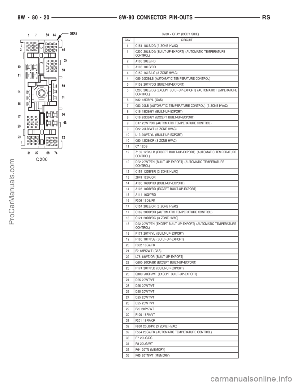
C200 - GRAY (BODY SIDE)
CAV CIRCUIT
1 C151 18LB/DG (3 ZONE HVAC)
1 C200 20LB/DG (BUILT-UP-EXPORT) (AUTOMATIC TEMPERATURE
CONTROL)
2 A106 20LB/RD
3 A108 18LG/RD
4 C152 16LB/LG (3 ZONE HVAC)
4 C59 20DB/LB (AUTOMATIC TEMPERATURE CONTROL)
5 P159 20TN/DG (BUILT-UP-EXPORT)
5 C200 20LB/DG (EXCEPT BUILT-UP-EXPORT) (AUTOMATIC TEMPERATURE
CONTROL)
6 K32 18DB/YL (GAS)
7 C53 20LB (AUTOMATIC TEMPERATURE CONTROL) (3 ZONE HVAC)
8 C16 18DB/GY (BUILT-UP-EXPORT)
8 C16 20DB/GY (EXCEPT BUILT-UP-EXPORT)
9 D17 20WT/DG (AUTOMATIC TEMPERATURE CONTROL)
9 C22 20LB/WT (3 ZONE HVAC)
10 L13 20WT/YL (BUILT-UP-EXPORT)
10 C50 12DB/OR (3 ZONE HVAC)
11 C7 12DB
12 Z135 12BK/LB (EXCEPT BUILT-UP-EXPORT) (AUTOMATIC TEMPERATURE
CONTROL)
12 D22 20WT/TN (BUILT-UP-EXPORT) (AUTOMATIC TEMPERATURE
CONTROL)
12 C153 12DB/BR (3 ZONE HVAC)
13 Z849 12BK/OR
14 A105 16DB/RD (BUILT-UP-EXPORT)
14 A105 18DB/RD (EXCEPT BUILT-UP-EXPORT)
15 A114 16GY/RD
16 F306 16DB/PK
17 C154 20LB/OR (3 ZONE HVAC)
17 C169 20DB/OR (AUTOMATIC TEMPERATURE CONTROL)
18 C121 20DB/DG (3 ZONE HVAC)
18 D22 20WT/TN (EXCEPT BUILT-UP-EXPORT) (AUTOMATIC TEMPERATURE
CONTROL)
18 P171 20TN/YL (BUILT-UP-EXPORT)
19 P160 18TN/LG (BUILT-UP-EXPORT)
20 F302 18GY/PK
21 F2 18PK/WT (GAS)
22 L78 18WT/OR (BUILT-UP-EXPORT)
22 Q900 20OR/BK (EXCEPT BUILT-UP-EXPORT)
23 P174 20TN/LB (BUILT-UP-EXPORT)
23 Q100 20OR/WT (EXCEPT BUILT-UP-EXPORT)
24 D25 20WT/VT
25 D25 20WT/VT
26 D25 20WT/VT
27 D25 20WT/VT
28 D25 20WT/VT
29 F20 20PK/WT
30 F100 18PK/VT
31 F201 18PK/OR
32 F850 20LB/PK (3 ZONE HVAC)
32 F504 20GY/PK (AUTOMATIC TEMPERATURE CONTROL)
33 P7 20LG/DG
34 P8 20LG/WT
35 P64 20TN (MEMORY)
36 P65 20TN/VT (MEMORY)
8W - 80 - 20 8W-80 CONNECTOR PIN-OUTSRS
ProCarManuals.com