sensor CHRYSLER VOYAGER 2002 Service Manual
[x] Cancel search | Manufacturer: CHRYSLER, Model Year: 2002, Model line: VOYAGER, Model: CHRYSLER VOYAGER 2002Pages: 2399, PDF Size: 57.96 MB
Page 1150 of 2399
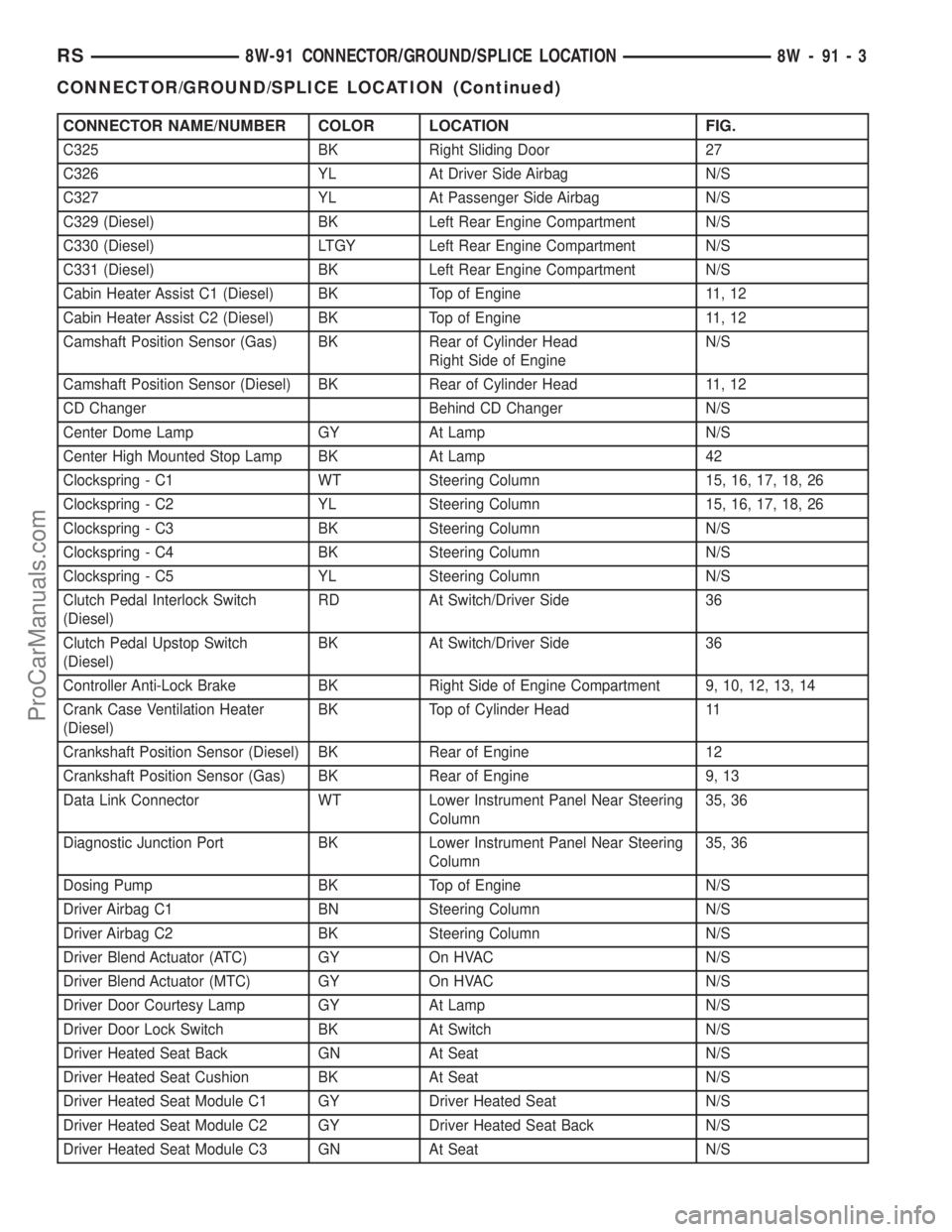
CONNECTOR NAME/NUMBER COLOR LOCATION FIG.
C325 BK Right Sliding Door 27
C326 YL At Driver Side Airbag N/S
C327 YL At Passenger Side Airbag N/S
C329 (Diesel) BK Left Rear Engine Compartment N/S
C330 (Diesel) LTGY Left Rear Engine Compartment N/S
C331 (Diesel) BK Left Rear Engine Compartment N/S
Cabin Heater Assist C1 (Diesel) BK Top of Engine 11, 12
Cabin Heater Assist C2 (Diesel) BK Top of Engine 11, 12
Camshaft Position Sensor (Gas) BK Rear of Cylinder Head
Right Side of EngineN/S
Camshaft Position Sensor (Diesel) BK Rear of Cylinder Head 11, 12
CD Changer Behind CD Changer N/S
Center Dome Lamp GY At Lamp N/S
Center High Mounted Stop Lamp BK At Lamp 42
Clockspring - C1 WT Steering Column 15, 16, 17, 18, 26
Clockspring - C2 YL Steering Column 15, 16, 17, 18, 26
Clockspring - C3 BK Steering Column N/S
Clockspring - C4 BK Steering Column N/S
Clockspring - C5 YL Steering Column N/S
Clutch Pedal Interlock Switch
(Diesel)RD At Switch/Driver Side 36
Clutch Pedal Upstop Switch
(Diesel)BK At Switch/Driver Side 36
Controller Anti-Lock Brake BK Right Side of Engine Compartment 9, 10, 12, 13, 14
Crank Case Ventilation Heater
(Diesel)BK Top of Cylinder Head 11
Crankshaft Position Sensor (Diesel) BK Rear of Engine 12
Crankshaft Position Sensor (Gas) BK Rear of Engine 9, 13
Data Link Connector WT Lower Instrument Panel Near Steering
Column35, 36
Diagnostic Junction Port BK Lower Instrument Panel Near Steering
Column35, 36
Dosing Pump BK Top of Engine N/S
Driver Airbag C1 BN Steering Column N/S
Driver Airbag C2 BK Steering Column N/S
Driver Blend Actuator (ATC) GY On HVAC N/S
Driver Blend Actuator (MTC) GY On HVAC N/S
Driver Door Courtesy Lamp GY At Lamp N/S
Driver Door Lock Switch BK At Switch N/S
Driver Heated Seat Back GN At Seat N/S
Driver Heated Seat Cushion BK At Seat N/S
Driver Heated Seat Module C1 GY Driver Heated Seat N/S
Driver Heated Seat Module C2 GY Driver Heated Seat Back N/S
Driver Heated Seat Module C3 GN At Seat N/S
RS8W-91 CONNECTOR/GROUND/SPLICE LOCATION8W-91-3
CONNECTOR/GROUND/SPLICE LOCATION (Continued)
ProCarManuals.com
Page 1151 of 2399
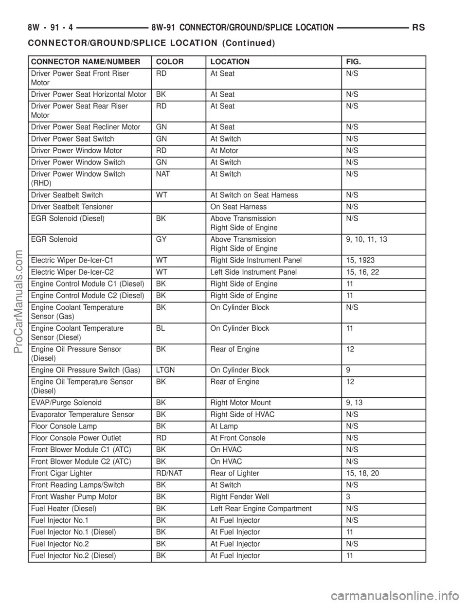
CONNECTOR NAME/NUMBER COLOR LOCATION FIG.
Driver Power Seat Front Riser
MotorRD At Seat N/S
Driver Power Seat Horizontal Motor BK At Seat N/S
Driver Power Seat Rear Riser
MotorRD At Seat N/S
Driver Power Seat Recliner Motor GN At Seat N/S
Driver Power Seat Switch GN At Switch N/S
Driver Power Window Motor RD At Motor N/S
Driver Power Window Switch GN At Switch N/S
Driver Power Window Switch
(RHD)NAT At Switch N/S
Driver Seatbelt Switch WT At Switch on Seat Harness N/S
Driver Seatbelt Tensioner On Seat Harness N/S
EGR Solenoid (Diesel) BK Above Transmission
Right Side of EngineN/S
EGR Solenoid GY Above Transmission
Right Side of Engine9, 10, 11, 13
Electric Wiper De-Icer-C1 WT Right Side Instrument Panel 15, 1923
Electric Wiper De-Icer-C2 WT Left Side Instrument Panel 15, 16, 22
Engine Control Module C1 (Diesel) BK Right Side of Engine 11
Engine Control Module C2 (Diesel) BK Right Side of Engine 11
Engine Coolant Temperature
Sensor (Gas)BK On Cylinder Block N/S
Engine Coolant Temperature
Sensor (Diesel)BL On Cylinder Block 11
Engine Oil Pressure Sensor
(Diesel)BK Rear of Engine 12
Engine Oil Pressure Switch (Gas) LTGN On Cylinder Block 9
Engine Oil Temperature Sensor
(Diesel)BK Rear of Engine 12
EVAP/Purge Solenoid BK Right Motor Mount 9, 13
Evaporator Temperature Sensor BK Right Side of HVAC N/S
Floor Console Lamp BK At Lamp N/S
Floor Console Power Outlet RD At Front Console N/S
Front Blower Module C1 (ATC) BK On HVAC N/S
Front Blower Module C2 (ATC) BK On HVAC N/S
Front Cigar Lighter RD/NAT Rear of Lighter 15, 18, 20
Front Reading Lamps/Switch BK At Switch N/S
Front Washer Pump Motor BK Right Fender Well 3
Fuel Heater (Diesel) BK Left Rear Engine Compartment N/S
Fuel Injector No.1 BK At Fuel Injector N/S
Fuel Injector No.1 (Diesel) BK At Fuel Injector 11
Fuel Injector No.2 BK At Fuel Injector N/S
Fuel Injector No.2 (Diesel) BK At Fuel Injector 11
8W - 91 - 4 8W-91 CONNECTOR/GROUND/SPLICE LOCATIONRS
CONNECTOR/GROUND/SPLICE LOCATION (Continued)
ProCarManuals.com
Page 1152 of 2399
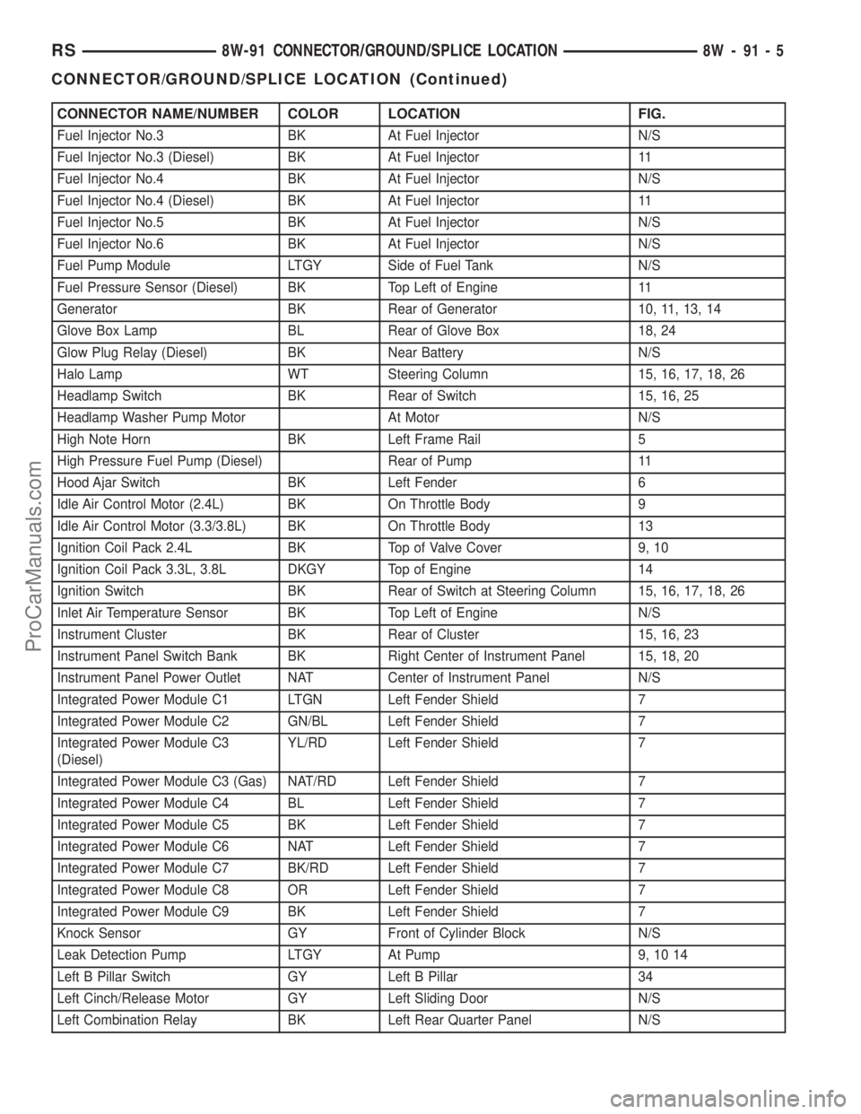
CONNECTOR NAME/NUMBER COLOR LOCATION FIG.
Fuel Injector No.3 BK At Fuel Injector N/S
Fuel Injector No.3 (Diesel) BK At Fuel Injector 11
Fuel Injector No.4 BK At Fuel Injector N/S
Fuel Injector No.4 (Diesel) BK At Fuel Injector 11
Fuel Injector No.5 BK At Fuel Injector N/S
Fuel Injector No.6 BK At Fuel Injector N/S
Fuel Pump Module LTGY Side of Fuel Tank N/S
Fuel Pressure Sensor (Diesel) BK Top Left of Engine 11
Generator BK Rear of Generator 10, 11, 13, 14
Glove Box Lamp BL Rear of Glove Box 18, 24
Glow Plug Relay (Diesel) BK Near Battery N/S
Halo Lamp WT Steering Column 15, 16, 17, 18, 26
Headlamp Switch BK Rear of Switch 15, 16, 25
Headlamp Washer Pump Motor At Motor N/S
High Note Horn BK Left Frame Rail 5
High Pressure Fuel Pump (Diesel) Rear of Pump 11
Hood Ajar Switch BK Left Fender 6
Idle Air Control Motor (2.4L) BK On Throttle Body 9
Idle Air Control Motor (3.3/3.8L) BK On Throttle Body 13
Ignition Coil Pack 2.4L BK Top of Valve Cover 9, 10
Ignition Coil Pack 3.3L, 3.8L DKGY Top of Engine 14
Ignition Switch BK Rear of Switch at Steering Column 15, 16, 17, 18, 26
Inlet Air Temperature Sensor BK Top Left of Engine N/S
Instrument Cluster BK Rear of Cluster 15, 16, 23
Instrument Panel Switch Bank BK Right Center of Instrument Panel 15, 18, 20
Instrument Panel Power Outlet NAT Center of Instrument Panel N/S
Integrated Power Module C1 LTGN Left Fender Shield 7
Integrated Power Module C2 GN/BL Left Fender Shield 7
Integrated Power Module C3
(Diesel)YL/RD Left Fender Shield 7
Integrated Power Module C3 (Gas) NAT/RD Left Fender Shield 7
Integrated Power Module C4 BL Left Fender Shield 7
Integrated Power Module C5 BK Left Fender Shield 7
Integrated Power Module C6 NAT Left Fender Shield 7
Integrated Power Module C7 BK/RD Left Fender Shield 7
Integrated Power Module C8 OR Left Fender Shield 7
Integrated Power Module C9 BK Left Fender Shield 7
Knock Sensor GY Front of Cylinder Block N/S
Leak Detection Pump LTGY At Pump 9, 10 14
Left B Pillar Switch GY Left B Pillar 34
Left Cinch/Release Motor GY Left Sliding Door N/S
Left Combination Relay BK Left Rear Quarter Panel N/S
RS8W-91 CONNECTOR/GROUND/SPLICE LOCATION8W-91-5
CONNECTOR/GROUND/SPLICE LOCATION (Continued)
ProCarManuals.com
Page 1153 of 2399

CONNECTOR NAME/NUMBER COLOR LOCATION FIG.
Left Cylinder Lock Switch BK At Switch N/S
Left Door Speaker BK At Speaker N/S
Left Fog Lamp WT At Lamp N/S
Left Front Door Ajar Switch BK At Switch N/S
Left Front Door Lock Motor/Ajar
SwitchBK Left Door N/S
Left Front Park/Turn Signal Lamp BK At Lamp 1, 5
Left Front Wheel Speed Sensor BK Left Fender Side Shield N/S
Left Full Open Switch BK Left Sliding Door N/S
Left Headlamp BK At Lamp 1, 5
Left Headlamp Leveling Motor WT At Motor N/S
Left High Beam Lamp BK At Lamp N/S
Left Instrument Panel Speaker BK At Speaker 15, 16, 22
Left Liftgate Flood Lamp GY At Lamp 42
Left Low Beam Lamp BK At Lamp N/S
Left Mid Reading Lamp GY At Lamp N/S
Left Park Lamp BK At Lamp N/S
Left Power Mirror BK At Mirror 22
Left Rear Lamp Assembly BK At Lamp 40
Left Rear Reading Lamp GY At Lamp N/S
Left Rear Speaker BK At Speaker 40
Left Rear Vent Motor NAT At Motor 39, 40
Left Rear Wheel Speed Sensor BK Center Rear of Floor Pan 40
Left Remote Radio Switch Steering Wheel N/S
Left Repeater Lamp GY Left Front Fender 4
Left Seat Airbag YL Left Seat N/S
Left Side Impact Airbag Control
ModuleYL/RD Left B Pillar 34
Left Sliding Door Control Module
C1BK Left Sliding Door N/S
Left Sliding Door Control Module
C2BK/RD Left Sliding Door N/S
Left Sliding Door Latch Sensing
SwitchBK Left Sliding Door N/S
Left Sliding Door Lock Motor BK Left Sliding Door N/S
Left Sliding Door Lock Motor/Ajar
SwitchBK Left Sliding Door N/S
Left Sliding Door Motor BK Left Sliding Door N/S
Left Speed Control Switch WT Steering Wheel N/S
Left Stop/Turn Signal Relay BK Left Quarter Panel N/S
Left Turn Signal Lamp OR AT Lamp N/S
Left Visor/Vanity Lamp BK At Lamp N/S
License Lamp DKGY At Lamp 42
Lift Pump Motor BK Left Rear Engine Compartment N/S
8W - 91 - 6 8W-91 CONNECTOR/GROUND/SPLICE LOCATIONRS
CONNECTOR/GROUND/SPLICE LOCATION (Continued)
ProCarManuals.com
Page 1154 of 2399

CONNECTOR NAME/NUMBER COLOR LOCATION FIG.
Liftgate Ajar Switch (Manual
Release)BK At Latch 42
Liftgate Ajar Switch (Power
Release)BK Lower Liftgate 42
Liftgate Cinch/Release Motor BL Liftgate N/S
Liftgate Cylinder Lock Switch BK At Switch 42
Liftgate Left Pinch Sensor BK Left Side of Liftgate N/S
Liftgate Right Pinch Sensor BK Right Side of Liftgate N/S
Low Note Horn BK Left Frame Rail 5
Manifold Absolute Pressure Sensor BK On Intake 10
Mass Air Flow Sensor (Diesel) OR Top of Engine 11, 12
Memory Seat/Mirror Module C1 GY Under Driver Seat N/S
Memory Seat/Mirror Module C2 GY Under Driver Seat N/S
Memory Seat/Mirror Module C3 WT Under Driver Seat N/S
Memory Seat/Mirror Module C4 GY Under Driver Seat N/S
Memory Seat Front Vertical Motor RD Under Seat N/S
Memory Seat Front Vertical
Position SensorBK Under Seat N/S
Memory Seat Horizontal Motor BK Under Seat N/S
Memory Seat Horizontal Position
SensorBK Under Seat N/S
Memory Seat Rear Vertical Motor RD Under Seat N/S
Memory Seat Rear Vertical Position
SensorBK Under Seat N/S
Memory Seat Recliner Motor GN Under Seat N/S
Memory Seat Recliner Position
SensorBK Under Seat N/S
Memory Seat Switch BK At Switch Driver Door N/S
Message Center WT Rear of Message Center 15, 16, 23
Mode Door Actuator GY Left Side of HVAC N/S
Multi Function Switch BK At Steering Column 15, 16, 17, 18, 26
Output Speed Sensor GY Front of Transmission 14
Overhead Console BK Front of Console N/S
Oxygen Sensor 1/1 Upstream BK Rear of Engine 9, 10, 14
Oxygen Sensor 1/2 Downstream BK Rear of Engine 9, 10, 14
Park/Neutral Positon Switch BK Front of Transmission 10
Passenger Airbag YL Passenger Side of Instrument Panel 15, 18, 19 24
Passenger Blend Door Actuator On HVAC N/S
Passenger Door Courtesy Lamp BK At Lamp 37
Passenger Door Lock Switch BK At Switch 37
Passenger Folding Mirror Relay BL Right Kick Panel N/S
Passenger Heated Seat Back GN At Seat N/S
Passenger Heated Seat Cushion BK At Seat N/S
Passenger Heated Seat Module C1 GY At Heated Seat N/S
RS8W-91 CONNECTOR/GROUND/SPLICE LOCATION8W-91-7
CONNECTOR/GROUND/SPLICE LOCATION (Continued)
ProCarManuals.com
Page 1156 of 2399

CONNECTOR NAME/NUMBER COLOR LOCATION FIG.
Rear Blower Motor Power Module
C2Right Quarter N/S
Rear Blower Rear Control Switch
C1Overhead N/S
Rear Blower Rear Control Switch
C2Overhead N/S
Rear Power Outlet RD Left Quarter Panel 40
Rear Temperature Motor Right Quarter N/S
Rear Washer Pump Motor BK Right Fender Well 3
Rear Wiper Motor GY At Motor 42
Recirculation Door Actuator GY Right Side of HVAC N/S
Remote Keyless Entry Antenna
(JAPAN)BK Right Upper Instrument Panel 23
Remote Keyless Entry Module BK/RD Top Left of I.P. 15, 16
Right B-Pillar Switch GY Right B Pillar 33
Right Cinch/Release Motor GY Rear of Sliding Door 38
Right Combination Relay BK Left Quarter Panel N/S
Right Cylinder Lock Switch BK Right Front Door 37
Right Door Speaker BK/RD At Speaker N/S
Right Fog Lamp WT At Lamp 3
Right Front Door Ajar Switch BK At B Pillar N/S
Right Front Door Lock Motor/Ajar
SwitchBK Right Front Door 37
Right Front Park/Turn Signal Lamp BK At Lamp 1, 3
Right Front Wheel Speed Sensor GY Right Fender Side Shield 9, 12, 13
Right Full Open Switch BK Right Sliding Door 38
Right Headlamp BK At Lamp 1, 3
Right Headlamp Leveling Motor WT At Right Headlamp N/S
Right High Beam Lamp BK At Right Headlamp N/S
Right Instrument Panel Speaker BK At Speaker 15, 18, 19
Right Liftgate Flood Lamp BK At Lamp 42
Right Low Beam Lamp BK At Right Headlamp N/S
Right Mid Reading Lamp GY At Lamp N/S
Right Park Lamp BK AT Lamp N/S
Right Power Mirror BK At Mirror 15, 19, 23
Right Rear Lamp Assembly BK At Lamp 41
Right Rear Pillar Speaker BK At Speaker 41
Right Rear Reading Lamp GY At Lamp N/S
Right Rear Speaker BK/RD At Speaker 41
Right Rear Vent Motor NAT At Motor 41
Right Rear Wheel Speed Sensor BK Center Rear of Floor Pan 41
Right Remote Radio Switch BK At Steering Wheel N/S
Right Repeater Lamp GY Right Front Fender 33
RS8W-91 CONNECTOR/GROUND/SPLICE LOCATION8W-91-9
CONNECTOR/GROUND/SPLICE LOCATION (Continued)
ProCarManuals.com
Page 1157 of 2399
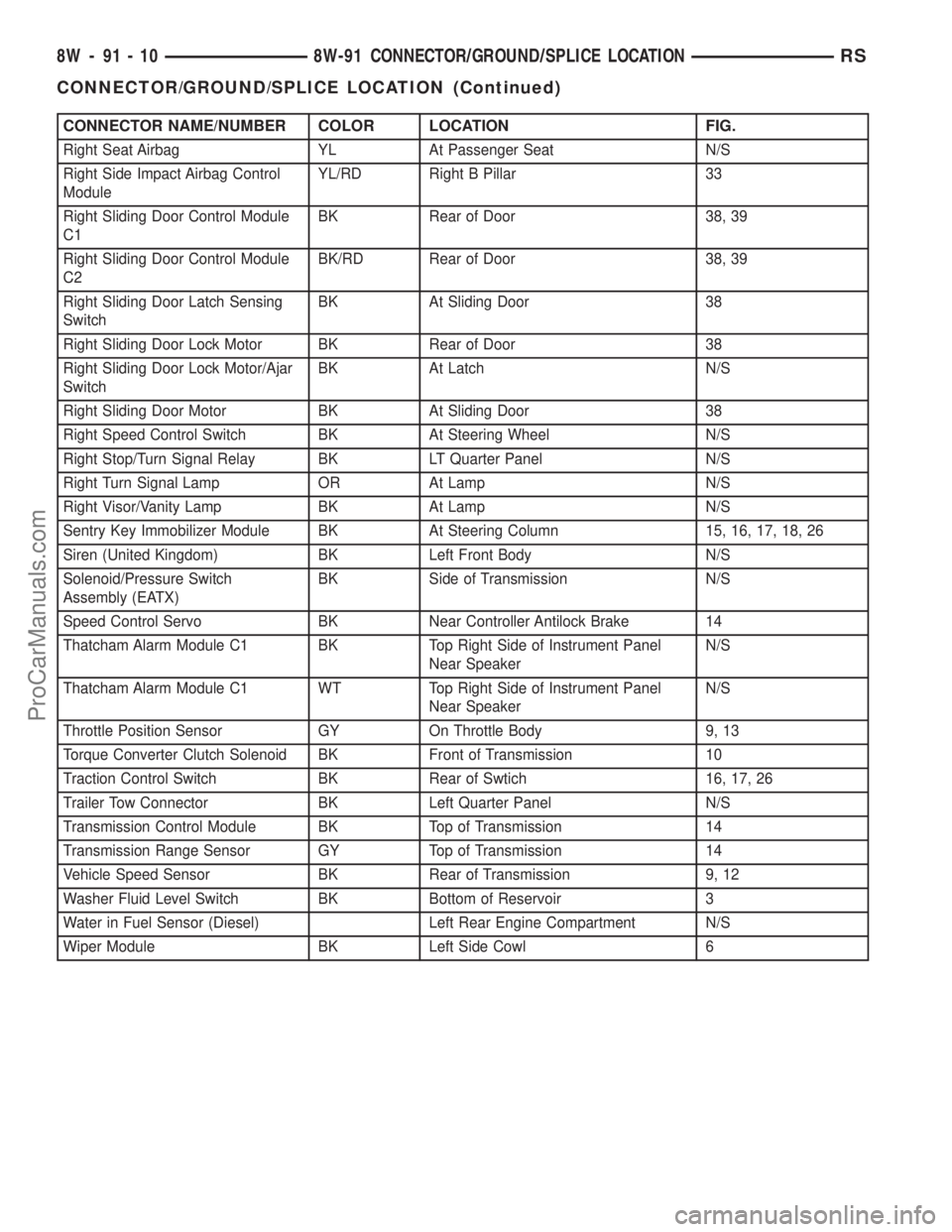
CONNECTOR NAME/NUMBER COLOR LOCATION FIG.
Right Seat Airbag YL At Passenger Seat N/S
Right Side Impact Airbag Control
ModuleYL/RD Right B Pillar 33
Right Sliding Door Control Module
C1BK Rear of Door 38, 39
Right Sliding Door Control Module
C2BK/RD Rear of Door 38, 39
Right Sliding Door Latch Sensing
SwitchBK At Sliding Door 38
Right Sliding Door Lock Motor BK Rear of Door 38
Right Sliding Door Lock Motor/Ajar
SwitchBK At Latch N/S
Right Sliding Door Motor BK At Sliding Door 38
Right Speed Control Switch BK At Steering Wheel N/S
Right Stop/Turn Signal Relay BK LT Quarter Panel N/S
Right Turn Signal Lamp OR At Lamp N/S
Right Visor/Vanity Lamp BK At Lamp N/S
Sentry Key Immobilizer Module BK At Steering Column 15, 16, 17, 18, 26
Siren (United Kingdom) BK Left Front Body N/S
Solenoid/Pressure Switch
Assembly (EATX)BK Side of Transmission N/S
Speed Control Servo BK Near Controller Antilock Brake 14
Thatcham Alarm Module C1 BK Top Right Side of Instrument Panel
Near SpeakerN/S
Thatcham Alarm Module C1 WT Top Right Side of Instrument Panel
Near SpeakerN/S
Throttle Position Sensor GY On Throttle Body 9, 13
Torque Converter Clutch Solenoid BK Front of Transmission 10
Traction Control Switch BK Rear of Swtich 16, 17, 26
Trailer Tow Connector BK Left Quarter Panel N/S
Transmission Control Module BK Top of Transmission 14
Transmission Range Sensor GY Top of Transmission 14
Vehicle Speed Sensor BK Rear of Transmission 9, 12
Washer Fluid Level Switch BK Bottom of Reservoir 3
Water in Fuel Sensor (Diesel) Left Rear Engine Compartment N/S
Wiper Module BK Left Side Cowl 6
8W - 91 - 10 8W-91 CONNECTOR/GROUND/SPLICE LOCATIONRS
CONNECTOR/GROUND/SPLICE LOCATION (Continued)
ProCarManuals.com
Page 1158 of 2399
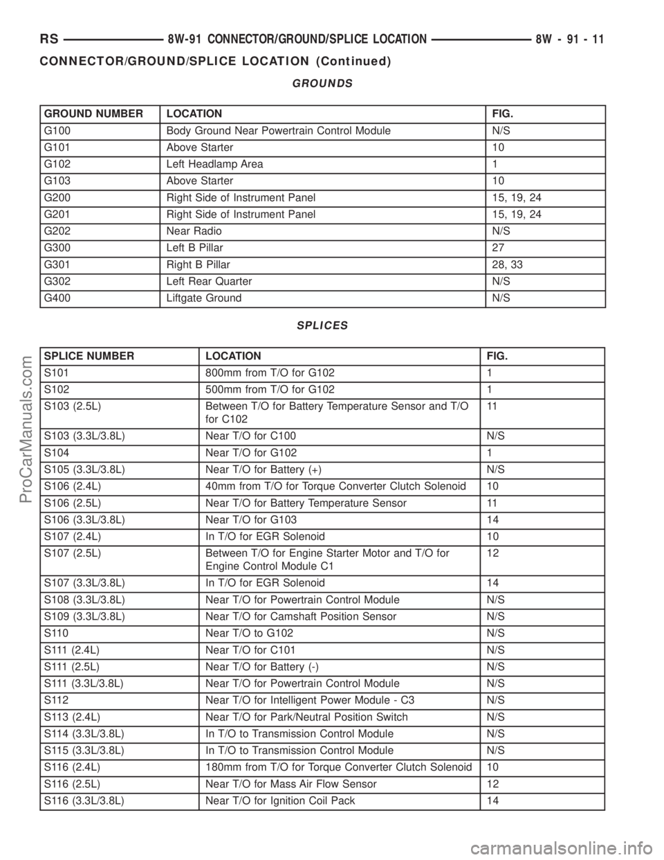
GROUNDS
GROUND NUMBER LOCATION FIG.
G100 Body Ground Near Powertrain Control Module N/S
G101 Above Starter 10
G102 Left Headlamp Area 1
G103 Above Starter 10
G200 Right Side of Instrument Panel 15, 19, 24
G201 Right Side of Instrument Panel 15, 19, 24
G202 Near Radio N/S
G300 Left B Pillar 27
G301 Right B Pillar 28, 33
G302 Left Rear Quarter N/S
G400 Liftgate Ground N/S
SPLICES
SPLICE NUMBER LOCATION FIG.
S101 800mm from T/O for G102 1
S102 500mm from T/O for G102 1
S103 (2.5L) Between T/O for Battery Temperature Sensor and T/O
for C10211
S103 (3.3L/3.8L) Near T/O for C100 N/S
S104 Near T/O for G102 1
S105 (3.3L/3.8L) Near T/O for Battery (+) N/S
S106 (2.4L) 40mm from T/O for Torque Converter Clutch Solenoid 10
S106 (2.5L) Near T/O for Battery Temperature Sensor 11
S106 (3.3L/3.8L) Near T/O for G103 14
S107 (2.4L) In T/O for EGR Solenoid 10
S107 (2.5L) Between T/O for Engine Starter Motor and T/O for
Engine Control Module C112
S107 (3.3L/3.8L) In T/O for EGR Solenoid 14
S108 (3.3L/3.8L) Near T/O for Powertrain Control Module N/S
S109 (3.3L/3.8L) Near T/O for Camshaft Position Sensor N/S
S110 Near T/O to G102 N/S
S111 (2.4L) Near T/O for C101 N/S
S111 (2.5L) Near T/O for Battery (-) N/S
S111 (3.3L/3.8L) Near T/O for Powertrain Control Module N/S
S112 Near T/O for Intelligent Power Module - C3 N/S
S113 (2.4L) Near T/O for Park/Neutral Position Switch N/S
S114 (3.3L/3.8L) In T/O to Transmission Control Module N/S
S115 (3.3L/3.8L) In T/O to Transmission Control Module N/S
S116 (2.4L) 180mm from T/O for Torque Converter Clutch Solenoid 10
S116 (2.5L) Near T/O for Mass Air Flow Sensor 12
S116 (3.3L/3.8L) Near T/O for Ignition Coil Pack 14
RS8W-91 CONNECTOR/GROUND/SPLICE LOCATION8W-91-11
CONNECTOR/GROUND/SPLICE LOCATION (Continued)
ProCarManuals.com
Page 1159 of 2399
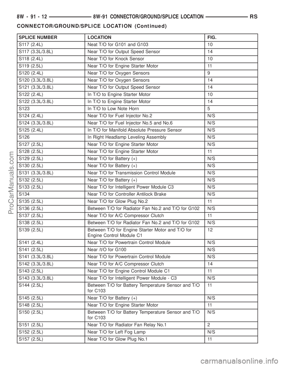
SPLICE NUMBER LOCATION FIG.
S117 (2.4L) Neat T/O for G101 and G103 10
S117 (3.3L/3.8L) Near T/O for Output Speed Sensor 14
S118 (2.4L) Near T/O for Knock Sensor 10
S119 (2.5L) Near T/O for Engine Starter Motor 11
S120 (2.4L) Near T/O for Oxygen Sensors 9
S120 (3.3L/3.8L) Near T/O for Oxygen Sensors 14
S121 (3.3L/3.8L) Near T/O for Output Speed Sensor 14
S122 (2.4L) In T/O to Engine Starter Motor 10
S122 (3.3L/3.8L) In T/O to Engine Starter Motor 14
S123 In T/O to Low Note Horn 5
S124 (2.4L) Near T/O for Fuel Injector No.2 N/S
S124 (3.3L/3.8L) Near T/O for Fuel Injector No.5 and No.6 N/S
S125 (2.4L) In T/O for Manifold Absolute Pressure Sensor N/S
S126 In Right Headlamp Leveling Assembly N/S
S127 (2.5L) Near T/O for Engine Starter Motor N/S
S128 (2.5L) Near T/O for Engine Starter Motor 11
S129 (2.5L) Near T/O for Battery (+) N/S
S130 (2.5L) Near T/O for Battery (+) N/S
S131 (3.3L/3.8L) Near T/O for Transmission Control Module N/S
S132 (2.5L) Near T/O for Battery (+) N/S
S133 (2.5L) Near T/O for Intelligent Power Module C3 N/S
S134 Near T/O for Controller Antilock Brake N/S
S135 (2.5L) Near T/O for Glow Plug No.2 11
S136 (2.5L) Between T/O for Radiator Fan No.2 and T/O for G102 N/S
S137 (2.5L) Near T/O for A/C Compressor Clutch 11
S138 (2.5L) Between T/O for Radiator Fan No.2 and T/O for G102 N/S
S139 (2.5L) Between T/O for Engine Starter Motor and T/O for
Engine Control Module C112
S141 (2.4L) Near T/O for Powertrain Control Module N/S
S141 (2.5L) Near /t/O for G100 N/S
S141 (3.3L/3.8L) Near T/O for Powertrain Control Module N/S
S142 (3.3L/3.8L) Near T/O for A/C Compressor Clutch 14
S143 (2.5L) Near T/O for Engine Control Module C1 11
S143 (3.3L/3.8L) Near T/O for Intelligent Power Module - C3 N/S
S144 (2.5L) Between T/O for Battery Temperature Sensor and T/O
for C10311
S145 (2.5L) Near T/O for Battery (+) N/S
S148 (2.5L) Near T/O for Engine Starter Motor 11
S150 (2.5L) Between T/O for Battery Temperature Sensor and T/O
for C103N/S
S151 (2.5L) Near T/O for Radiator Fan Relay No.1 2
S152 (2.5L) Near T/O for Left Fog Lamp N/S
S157 (2.5L) Near T/O for Glow Plug No.1 11
8W - 91 - 12 8W-91 CONNECTOR/GROUND/SPLICE LOCATIONRS
CONNECTOR/GROUND/SPLICE LOCATION (Continued)
ProCarManuals.com
Page 1208 of 2399
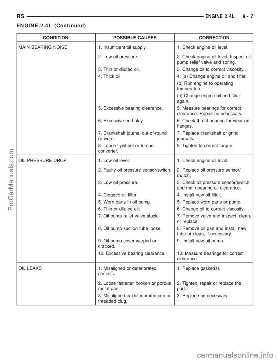
CONDITION POSSIBLE CAUSES CORRECTION
MAIN BEARING NOISE 1. Insufficient oil supply. 1. Check engine oil level.
2. Low oil pressure. 2. Check engine oil level. Inspect oil
pump relief valve and spring.
3. Thin or diluted oil. 3. Change oil to correct viscosity.
4. Thick oil 4. (a) Change engine oil and filter.
(b) Run engine to operating
temperature.
(c) Change engine oil and filter
again.
5. Excessive bearing clearance. 5. Measure bearings for correct
clearance. Repair as necessary.
6. Excessive end play. 6. Check thrust bearing for wear on
flanges.
7. Crankshaft journal out-of-round
or worn.7. Replace crankshaft or grind
journals.
8. Loose flywheel or torque
converter.8. Tighten to correct torque.
OIL PRESSURE DROP 1. Low oil level. 1. Check engine oil level.
2. Faulty oil pressure sensor/switch. 2. Replace oil pressure sensor/
switch.
3. Low oil pressure. 3. Check oil pressure sensor/switch
and main bearing oil clearance.
4. Clogged oil filter. 4. Install new oil filter.
5. Worn parts in oil pump. 5. Replace worn parts or pump.
6. Thin or diluted oil. 6. Change oil to correct viscosity.
7. Oil pump relief valve stuck. 7. Remove valve and inspect, clean,
or replace.
8. Oil pump suction tube loose. 8. Remove oil pan and install new
tube or clean, if necessary.
9. Oil pump cover warped or
cracked.9. Install new oil pump.
10. Excessive bearing clearance. 10. Measure bearings for correct
clearance.
OIL LEAKS 1. Misaligned or deteriorated
gaskets.1. Replace gasket(s).
2. Loose fastener, broken or porous
metal part.2. Tighten, repair or replace the
part.
3. Misaligned or deteriorated cup or
threaded plug.3. Replace as necessary.
RSENGINE 2.4L9-7
ENGINE 2.4L (Continued)
ProCarManuals.com