adding oil CHRYSLER VOYAGER 2002 Service Manual
[x] Cancel search | Manufacturer: CHRYSLER, Model Year: 2002, Model line: VOYAGER, Model: CHRYSLER VOYAGER 2002Pages: 2399, PDF Size: 57.96 MB
Page 250 of 2399

COOLING
TABLE OF CONTENTS
page page
COOLING
DESCRIPTION
DESCRIPTION - COOLING SYSTEM........1
DESCRIPTION - HOSE CLAMPS...........1
OPERATION
OPERATION - COOLING SYSTEM.........2
OPERATION - HOSE CLAMPS............2
DIAGNOSIS AND TESTING
DIAGNOSIS AND TESTING - COOLING
SYSTEM LEAK TEST....................2
DIAGNOSIS AND TESTING - COOLING
SYSTEM FLOW CHECK.................3
DIAGNOSIS AND TESTING - COOLING
SYSTEM AERATION....................4
DIAGNOSIS AND TESTING - COOLING
SYSTEM DEAERATION..................4
STANDARD PROCEDURE
STANDARD PROCEDURE - COOLING
SYSTEM DRAINING....................4STANDARD PROCEDURE - COOLING
SYSTEM FILLING......................4
STANDARD PROCEDURE - ADDING
ADDITIONAL COOLANT.................4
STANDARD PROCEDURE - COOLANT
LEVEL CHECK........................5
SPECIFICATIONS
COOLING SYSTEM CAPACITY............6
ACCESSORY DRIVE BELT TENSION.......6
TORQUE.............................6
SPECIAL TOOLS
COOLING SYSTEM.....................7
ACCESSORY DRIVE.......................8
ENGINE...............................14
TRANSMISSION.........................38
COOLING
DESCRIPTION
DESCRIPTION - COOLING SYSTEM
The cooling system components consist of a radia-
tor, electric fan motors, shroud, pressure cap, thermo-
stat, transmission oil cooler, water pump, hoses,
clamps, coolant, and a coolant reserve system to com-
plete the circuit.
DESCRIPTION - HOSE CLAMPS
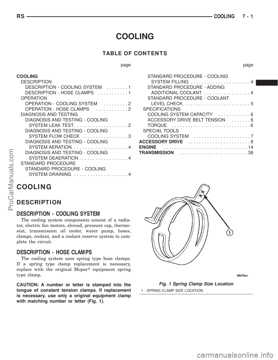
The cooling system uses spring type hose clamps.
If a spring type clamp replacement is necessary,
replace with the original Mopartequipment spring
type clamp.
CAUTION: A number or letter is stamped into the
tongue of constant tension clamps. If replacement
is necessary, use only a original equipment clamp
with matching number or letter (Fig. 1).
Fig. 1 Spring Clamp Size Location
1 - SPRING CLAMP SIZE LOCATION
RSCOOLING7-1
ProCarManuals.com
Page 305 of 2399

STANDARD PROCEDURE
STANDARD PROCEDURE - COOLANT SERVICE
For engine coolant recommended service schedule,
(Refer to LUBRICATION & MAINTENANCE/MAIN-
TENANCE SCHEDULES - DESCRIPTION).
STANDARD PROCEDURE - ADDING
ADDITIONAL COOLANT
The pressure/vent cap should not be removed
from the coolant recovery pressure container
when the engine is hot.When additional coolant is
needed to maintain this level, it should be added to
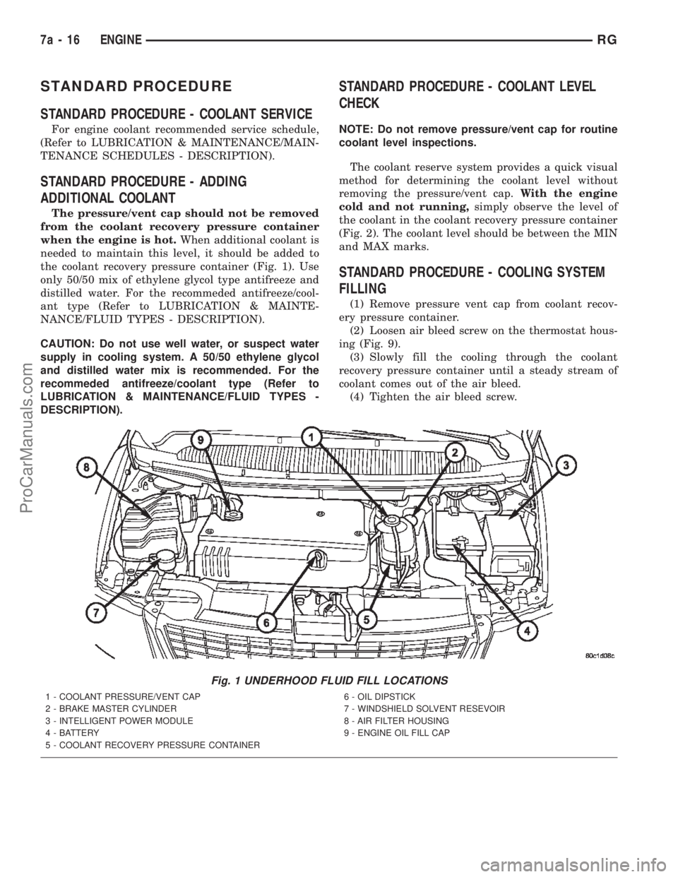
the coolant recovery pressure container (Fig. 1). Use
only 50/50 mix of ethylene glycol type antifreeze and
distilled water. For the recommeded antifreeze/cool-
ant type (Refer to LUBRICATION & MAINTE-
NANCE/FLUID TYPES - DESCRIPTION).
CAUTION: Do not use well water, or suspect water
supply in cooling system. A 50/50 ethylene glycol
and distilled water mix is recommended. For the
recommeded antifreeze/coolant type (Refer to
LUBRICATION & MAINTENANCE/FLUID TYPES -
DESCRIPTION).
STANDARD PROCEDURE - COOLANT LEVEL
CHECK
NOTE: Do not remove pressure/vent cap for routine
coolant level inspections.
The coolant reserve system provides a quick visual
method for determining the coolant level without
removing the pressure/vent cap.With the engine
cold and not running,simply observe the level of
the coolant in the coolant recovery pressure container
(Fig. 2). The coolant level should be between the MIN
and MAX marks.
STANDARD PROCEDURE - COOLING SYSTEM
FILLING
(1) Remove pressure vent cap from coolant recov-
ery pressure container.
(2) Loosen air bleed screw on the thermostat hous-
ing (Fig. 9).
(3) Slowly fill the cooling through the coolant
recovery pressure container until a steady stream of
coolant comes out of the air bleed.
(4) Tighten the air bleed screw.
Fig. 1 UNDERHOOD FLUID FILL LOCATIONS
1 - COOLANT PRESSURE/VENT CAP
2 - BRAKE MASTER CYLINDER
3 - INTELLIGENT POWER MODULE
4 - BATTERY
5 - COOLANT RECOVERY PRESSURE CONTAINER6 - OIL DIPSTICK
7 - WINDSHIELD SOLVENT RESEVOIR
8 - AIR FILTER HOUSING
9 - ENGINE OIL FILL CAP
7a - 16 ENGINERG
ProCarManuals.com
Page 1563 of 2399

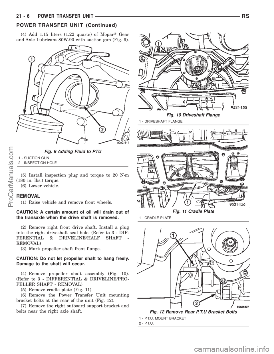
(4) Add 1.15 liters (1.22 quarts) of MopartGear
and Axle Lubricant 80W-90 with suction gun (Fig. 9).
(5) Install inspection plug and torque to 20 N´m
(180 in. lbs.) torque.
(6) Lower vehicle.
REMOVAL
(1) Raise vehicle and remove front wheels.
CAUTION: A certain amount of oil will drain out of
the transaxle when the drive shaft is removed.
(2) Remove right front drive shaft. Install a plug
into the right driveshaft seal hole. (Refer to 3 - DIF-
FERENTIAL & DRIVELINE/HALF SHAFT -
REMOVAL)
(3) Mark propeller shaft front flange.
CAUTION: Do not let propeller shaft to hang freely.
Damage to the shaft will occur.
(4) Remove propeller shaft assembly (Fig. 10).
(Refer to 3 - DIFFERENTIAL & DRIVELINE/PRO-
PELLER SHAFT - REMOVAL)
(5) Remove cradle plate (Fig. 11).
(6) Remove the Power Transfer Unit mounting
bracket bolts at the rear of the unit (Fig. 12).
(7) Remove the right outboard support bracket and
bolts near the right axle shaft.
Fig. 11 Cradle Plate
1 - CRADLE PLATE
Fig. 12 Remove Rear P.T.U Bracket Bolts
1 - P.T.U. MOUNT BRACKET
2 - P.T.U.
Fig. 9 Adding Fluid to PTU
1 - SUCTION GUN
2 - INSPECTION HOLE
Fig. 10 Driveshaft Flange
1 - DRIVESHAFT FLANGE
21 - 6 POWER TRANSFER UNITRS
POWER TRANSFER UNIT (Continued)
ProCarManuals.com
Page 1829 of 2399

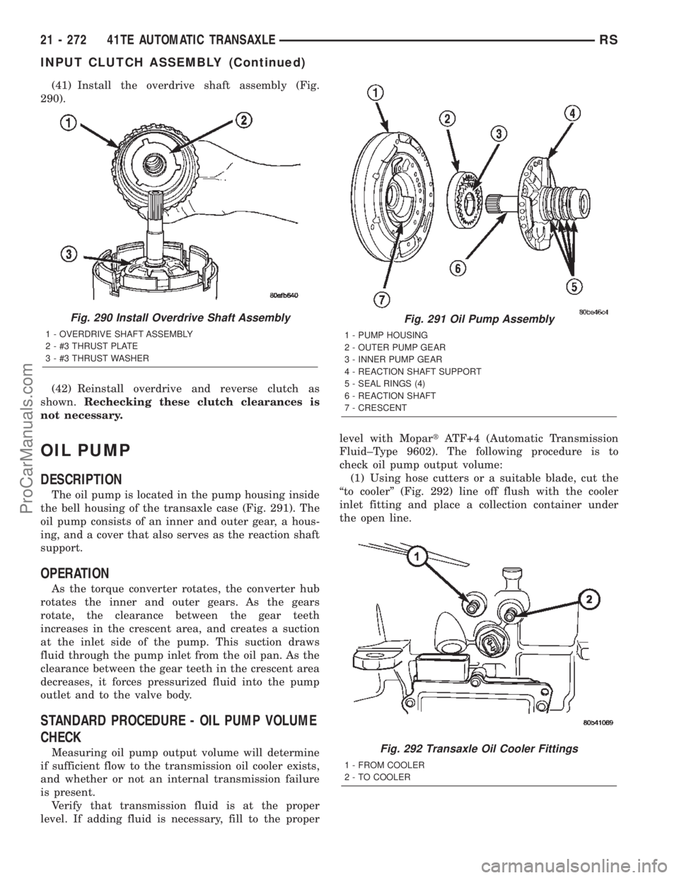
(41) Install the overdrive shaft assembly (Fig.
290).
(42) Reinstall overdrive and reverse clutch as
shown.Rechecking these clutch clearances is
not necessary.
OIL PUMP
DESCRIPTION
The oil pump is located in the pump housing inside
the bell housing of the transaxle case (Fig. 291). The
oil pump consists of an inner and outer gear, a hous-
ing, and a cover that also serves as the reaction shaft
support.
OPERATION
As the torque converter rotates, the converter hub
rotates the inner and outer gears. As the gears
rotate, the clearance between the gear teeth
increases in the crescent area, and creates a suction
at the inlet side of the pump. This suction draws
fluid through the pump inlet from the oil pan. As the
clearance between the gear teeth in the crescent area
decreases, it forces pressurized fluid into the pump
outlet and to the valve body.
STANDARD PROCEDURE - OIL PUMP VOLUME
CHECK
Measuring oil pump output volume will determine
if sufficient flow to the transmission oil cooler exists,
and whether or not an internal transmission failure
is present.
Verify that transmission fluid is at the proper
level. If adding fluid is necessary, fill to the properlevel with MopartATF+4 (Automatic Transmission
Fluid±Type 9602). The following procedure is to
check oil pump output volume:
(1) Using hose cutters or a suitable blade, cut the
ªto coolerº (Fig. 292) line off flush with the cooler
inlet fitting and place a collection container under
the open line.
Fig. 290 Install Overdrive Shaft Assembly
1 - OVERDRIVE SHAFT ASSEMBLY
2 - #3 THRUST PLATE
3 - #3 THRUST WASHER
Fig. 291 Oil Pump Assembly
1 - PUMP HOUSING
2 - OUTER PUMP GEAR
3 - INNER PUMP GEAR
4 - REACTION SHAFT SUPPORT
5 - SEAL RINGS (4)
6 - REACTION SHAFT
7 - CRESCENT
Fig. 292 Transaxle Oil Cooler Fittings
1 - FROM COOLER
2 - TO COOLER
21 - 272 41TE AUTOMATIC TRANSAXLERS
INPUT CLUTCH ASSEMBLY (Continued)
ProCarManuals.com
Page 1987 of 2399

RIGID, SEMI-RIGID, AND FLEXIBLE PLASTIC PARTS TYPES
CODE FAMILY NAME COMMON TRADE NAME TYPICAL APPLICATION
ASA ACRYLONITRILE STYRENE
ACRYLITELURAN S CONSOLES, GRILLES
ABS ACRYLONITRILE
BUTADIENE STYRENETERLURAN9A9PILLARS, CONSOLES,
GRILLES
ABS/PC ABS/PC ALLOY PULSE, PROLOY,
BAYBLENDDOORS, INSTRUMENT
PANELS
ABS/PVC ABS/PV ALLOY PROLOY, PULSE, LUSTRAN,
CYCLOVINDOOR PANELS, GRILLES,
TRIM
BMC BULK MOLDING
COMPOUNDBMC FENDER EXTENSIONS
EMA EHTYLENE METHYL
ACRYLATE/IONOMERSURLYN, EMA, IONOMER BUMPER GUARDS, PADS
METTON METTON METTON GRILLES, KICK PANELS,
RUNNING BOARDS
MPPO MODIFIED
POLYPHENYLENE OXIDEMPPO SPOILER ASSEMBLY
PA POLYAMID ZYTEL, VYDYNE, PA,
MINLONFENDERS, QUARTER PANELS
PET THERMOPLASTIC
POLYESTERRYNITE TRIM
PBT/PPO PBT/PPO ALLOY GERMAX CLADDINGS
PBTP POLYBUTYLENE
THEREPTHALATEPBT, PBTP, POCAN, VALOX WHEEL COVERS, FENDERS,
GRILLES
PBTP/EEBC POLYBUTYLENE
THEREPTHALATE/EEBC
ALLOYBEXLOY,9M9, PBTP/EEBC FASCIAS, ROCKER PANEL,
MOLDINGS
PC POLYCARBONATE LEXAN, MERLON, CALIBRE,
MAKROLON PCTAIL LIGHT LENSES, IP TRIM,
VALANCE PANELS
PC/ABS PC/ABS ALLOY GERMAX, BAY BLENDS,
PULSEDOORS, INSTRUMENT
PANELS
PPO POLYPHENYLENE OXIDE AZDEL, HOSTALEN,
MARLEX, PRFAX, NORYL,
GTX, PPOINTERIOR TRIM, DOOR
PANELS, SPLASH SHIELDS,
STEERING COLUMN SHROUD
PPO/PA POLYPHENYLENE/
POLYAMIDPPO/PA, GTX 910 FENDERS, QUARTER PANELS
PR/FV FIBERGLASS REINFORCED
PLASTICFIBERGLASS, FV, PR/FV BODY PANELS
PS POLYSTYRENE LUSTREX, STYRON, PS DOOR PANELS, DASH
PANELS
RTM RESIN TRANSFER
MOLDING COMPOUNDRTM BODY PANELS
SMC SHEET MOLDED
COMPOUNDSMC BODY PANELS
TMC TRANSFER MOLDING
COMPOUNDTMC GRILLES
23 - 4 BODYRS
BODY (Continued)
ProCarManuals.com
Page 1988 of 2399

CODE FAMILY NAME COMMON TRADE NAME TYPICAL APPLICATION
UP UNSATURATED
POLYESTER
(THERMOSETTING)SMC, BMC, TMC, ZMC, IMC,
XSMC, UPGRILLE OPENING PANEL,
LIFTGATES, FLARESIDE
FENDERS, FENDER
EXTENSIONS
EEBC ETHER/ESTER BLOCKED
CO-POLYMEREEBC BUMPERS
EEBC/PBTP EEBC/POLYBUTYLENE
TEREPTHALATEEEBC, PBTP, BEXLOY BUMPER, ROCKER PANELS
EMPP ETHYLENE MODIFIED
POLYPROPYLENEEMPP BUMPER COVERS
EPDM ETHYLENE/
PROPROPYLENE DIENE
MONOMEREPDM, NORDEL, VISTALON BUMPERS
EPM ETHYLENE/
PROPROPYLENE CO-
POLYMEREPM FENDERS
MPU FOAM POLYURETHANE MPU SPOILERS
PE POLYETHYLENE ALATHON, DYLAN,
LUPOLEN, MARLEX-
PP POLYPROPYLENE
(BLENDS)NORYL, AZDEL, MARLOX,
DYLON, PRAVEXINNER FENDER, SPOILERS,
KICK PANELS
PP/EPDM PP/EPDM ALLOY PP/EPDM SPOILERS, GRILLES
PUR POLYURETHANE COLONELS, PUR, PU FASCIAS, BUMPERS
PUR/PC PUR/PC ALLOY TEXIN BUMPERS
PVC POLYVINYL CHLORIDE APEX, GEON, VINYLITE BODY MOLDINGS, WIRE
INSULATION, STEERING
WHEELS
RIM REACTION INJECTED
MOLDED POLYURETHANERIM, BAYFLEX FRONT FASCIAS, MODULAR
WINDOWS
RRIM REINFORCED REACTION
INJECTED MOLDEDPUR, RRIM FASCIAS, BODY PANELS,
BODY TRIMS
TPE THERMO POLYETHYLENE TPE, HYTREL, BEXLOY-V FASCIAS, BUMPERS,
CLADDINGS
TPO THERMOPOLYOLEFIN POLYTROPE, RENFLEX,
SANTOPRENE, VISAFLEX,
ETA, APEX, TPO, SHIELDS,
CLADDINGSBUMPERS, END CAPS,
TELCAR, RUBBER, STRIPS,
SIGHT, INTERIOR B POST
TPP THERMO-
POLYPROPYLENETPP BUMPERS
TPU THERMOPOLYURETHANE,
POLYESTERTPU, HYTREL, TEXIN,
ESTANEBUMPERS, BODY SIDE,
MOLDINGS, FENDERS,
FASCIAS
RSBODY23-5
BODY (Continued)
ProCarManuals.com