egr CHRYSLER VOYAGER 2002 Service Manual
[x] Cancel search | Manufacturer: CHRYSLER, Model Year: 2002, Model line: VOYAGER, Model: CHRYSLER VOYAGER 2002Pages: 2399, PDF Size: 57.96 MB
Page 17 of 2399
WARNING: Ethanol vapors are extremely flammable
and could cause serious personal injury. Never
have any smoking materials lit in or near the vehi-
cle when removing the fuel filler tube cap (gas cap)
or filling the tank. Do not use E-85 as a cleaning
agent and never use it near an open flame.
FUEL REQUIREMENTS
The vehicle will operate on both unleaded gasoline
with an octane rating of 87, or E-85 fuel, or any mix-
ture of these two.
For best results, a refueling pattern that alternates
between E-85 and unleaded gasoline should be
avoided. When you do switch fuels, it is recom-
mended that
²you do not switch when the fuel gauge indicates
less than 1/4 full
²you do not add less than 5 gallons when refuel-
ing
²you operate the vehicle immediately after refuel-
ing for a period of at least 5 minutes
Observing these precautions will avoid possible
hard starting and/or significant deterioration in
driveability during warm up.
FFV STARTING
The characteristics of E-85 fuel make it unsuitable
for use when ambient temperatures fall below 0ÉF. In
the range of 0ÉF to 32ÉF, you may experience an
increase in the time it takes for your engine to start,
and a deterioration in driveability (sags and/or hesi-
tations) until the engine is fully warmed up.
Engine Operating on E-85 Fuel
If vehicle operates on E-85 fuel either full or part-
time, use only MopartFlexible Fuel 5W-30 engine oil
or an equivalent that meets DaimlerChrysler Stan-
dard MS-9214. Equivalent commercial Flexible Fuel
engine oils may be labeled as Multi-Fuel, Variable
Fuel, Flexible Fuel, etc. These engine oils may be
satisfactory if they meet the DaimlerChrysler Stan-
dard.
SAE 5W-30 engine oil is preferred for use in Flex-
ible Fuel engines.
CAUTION: If Flexible Fuel engine oil is not used
when using E-85 fuel, engine wear or damage may
result.
CRUISING RANGE
Because E-85 fuel contains less energy per gallon
than gasoline, you will experience an increase in fuel
consumption. You can expect your MPG and your
driving range to decrease by about 30% compared to
gasoline operation.
DESCRIPTION - AUTOMATIC TRANSMISSION
FLUID
NOTE: Refer to the maintenance schedules for the
recommended maintenance (fluid/filter change)
intervals for this transaxle.
NOTE: All transaxles have a common transmission
and differential sump. Filling the transaxle accom-
modates the differential as well.
TRANSMISSION FLUID
MopartATF+4 (Automatic Transmission Fluid-
Type 9602) is required in the 41TE automatic and
T850 manual transaxles. Substitute fluids can induce
torque converter clutch shudder.
MopartATF+4 (Automatic Transmission Fluid-
Type 9602) when new is red in color. The ATF is dyed
red so it can be identified from other fluids used in
the vehicle such as engine oil or antifreeze. The red
color is not permanent and is not an indicator of fluid
condition. As the vehicle is driven, the ATF will begin
to look darker in color and may eventually become
brown.This is normal.ATF+4 also has a unique
odor that may change with age. Consequently,odor
and color cannot be used to indicate the fluid
condition or the need for a fluid change.
FLUID ADDITIVES
DaimlerChrysler strongly recommends against the
addition of any fluids to the transmission, other than
those automatic transmission fluids listed above.
Exceptions to this policy are the use of special dyes
to aid in detecting fluid leaks.
Various ªspecialº additives and supplements exist
that claim to improve shift feel and/or quality. These
additives and others also claim to improve converter
clutch operation and inhibit overheating, oxidation,
varnish, and sludge. These claims have not been sup-
ported to the satisfaction of DaimlerChrysler and
these additivesmust not be used.The use of trans-
mission ªsealersº should also be avoided, since they
may adversely affect the integrity of transmission
seals.
DESCRIPTION - FUEL REQUIREMENTS
Your engine is designed to meet all emissions reg-
ulations and provide excellent fuel economy and per-
formance when using high quality unleaded gasoline
having an octane rating of 87. The use of premium
gasoline is not recommended. The use of premium
gasoline will provide no benefit over high quality reg-
ular gasoline, and in some circumstances may result
in poorer performance.
0 - 4 LUBRICATION & MAINTENANCERS
FLUID TYPES (Continued)
ProCarManuals.com
Page 21 of 2399
(2) When using another vehicle as a booster
source, park the booster vehicle within cable reach.
Turn off all accessories, set the parking brake, place
the automatic transmission in PARK or the manual
transmission in NEUTRAL and turn the ignition
OFF.
(3) On disabled vehicle, place gear selector in park
or neutral and set park brake. Turn off all accesso-
ries.
(4) Connect jumper cables to booster battery. RED
clamp to positive terminal (+). BLACK clamp to neg-
ative terminal (-). DO NOT allow clamps at opposite
end of cables to touch, electrical arc will result.
Review all warnings in this procedure.
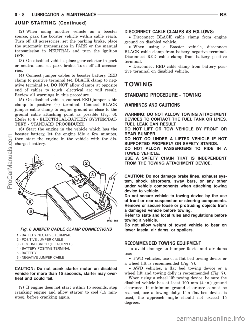
(5) On disabled vehicle, connect RED jumper cable
clamp to positive (+) terminal. Connect BLACK
jumper cable clamp to engine ground as close to the
ground cable attaching point as possible (Fig. 6).
(Refer to 8 - ELECTRICAL/BATTERY SYSTEM/BAT-
TERY - STANDARD PROCEDURE).
(6) Start the engine in the vehicle which has the
booster battery, let the engine idle a few minutes,
then start the engine in the vehicle with the dis-
charged battery.
CAUTION: Do not crank starter motor on disabled
vehicle for more than 15 seconds, starter may over-
heat and could fail.
(7) If engine does not start within 15 seconds, stop
cranking engine and allow starter to cool (15 min-
utes), before cranking again.DISCONNECT CABLE CLAMPS AS FOLLOWS:
²Disconnect BLACK cable clamp from engine
ground on disabled vehicle.
²When using a Booster vehicle, disconnect
BLACK cable clamp from battery negative terminal.
Disconnect RED cable clamp from battery positive
terminal.
²Disconnect RED cable clamp from battery posi-
tive terminal on disabled vehicle.
TOWING
STANDARD PROCEDURE - TOWING
WARNINGS AND CAUTIONS
WARNING: DO NOT ALLOW TOWING ATTACHMENT
DEVICES TO CONTACT THE FUEL TANK OR LINES,
FUEL LEAK CAN RESULT.
DO NOT LIFT OR TOW VEHICLE BY FRONT OR
REAR BUMPER.
DO NOT GO UNDER A LIFTED VEHICLE IF NOT
SUPPORTED PROPERLY ON SAFETY STANDS.
DO NOT ALLOW PASSENGERS TO RIDE IN A
TOWED VEHICLE.
USE A SAFETY CHAIN THAT IS INDEPENDENT
FROM THE TOWING ATTACHMENT DEVICE.
CAUTION: Do not damage brake lines, exhaust sys-
tem, shock absorbers, sway bars, or any other
under vehicle components when attaching towing
device to vehicle.
Do not secure vehicle to towing device by the use
of front or rear suspension or steering components.
Remove or secure loose or protruding objects from
a damaged vehicle before towing.
Refer to state and local rules and regulations before
towing a vehicle.
Do not allow weight of towed vehicle to bear on
lower fascia, air dams, or spoilers.
RECOMMENDED TOWING EQUIPMENT
To avoid damage to bumper fascia and air dams
use:
²FWD vehicles, use of a flat bed towing device or
a wheel lift is recommended (Fig. 7).
²AWD vehicles, a flat bed towing device or a
wheel lift and towing dolly is recommended (Fig. 7).
When using a wheel lift towing device, be sure the
disabled vehicle has at least 100 mm (4 in.) ground
clearance. If minimum ground clearance cannot be
reached, use a towing dolly. If a flat bed device is
used, the approach angle should not exceed 15
degrees.
Fig. 6 JUMPER CABLE CLAMP CONNECTIONS
1 - BATTERY NEGATIVE TERMINAL
2 - POSITIVE JUMPER CABLE
3 - TEST INDICATOR (IF EQUIPPED)
4 - BATTERY POSITIVE TERMINAL
5 - BATTERY
6 - NEGATIVE JUMPER CABLE
0 - 8 LUBRICATION & MAINTENANCERS
JUMP STARTING (Continued)
ProCarManuals.com
Page 33 of 2399
(7) If equipped with antilock brakes, install wheel
speed sensor and mounting bolt on steering knuckle
(Fig. 13). Tighten the speed sensor bolt to a torque of
7 N´m (60 in. lbs.).
(8) Install brake rotor on hub and bearing (Fig. 9).
(9) Install disc brake caliper and adapter assembly
on steering knuckle. Install adapter amounting bolts
and tighten to 169 N´m (125 ft. lbs.).
(10) Clean any debris from the threads of the
outer C/V joint stub axle.
(11) Install the washer and hub nut on stub axle.
(12) Have a helper apply the vehicle's brakes to
keep hub from turning, then tighten hub nut to a
torque of 244 N´m (180 ft. lbs.).
(13) Install the spring wave washer on the end of
the stub axle.
(14) Install the hub nut lock, and anewcotter pin
(Fig. 8). Wrap cotter pin prongs tightly around the
hub nut lock.
(15) Install wheel and tire assembly. Install and
tighten the wheel mounting nuts in proper sequence
until all nuts are torqued to half the required speci-
fication. Then repeat the tightening sequence to the
full specified torque of 135 N´m (100 ft. lbs.).
(16) Lower vehicle.
(17) Set front wheel alignment camber and toe as
necessary. (Refer to 2 - SUSPENSION/WHEEL
ALIGNMENT - STANDARD PROCEDURE)
LOWER BALL JOINT
DESCRIPTION
The ball joint is an integral part of the lower con-
trol arm (Fig. 1). The ball joint has a tapered stud
that is pressed into the aluminum knuckle. The ball
joint stud is threaded on the end for a retainer nut.
The ball joint has a non-vented seal boot. The seal
boot has an integrated heat shield.
The ball joint used in the lower control arm of this
vehicle is a sealed-for-life ball joint and requires no
maintenance lubrication. The ball joint has been
lubricated-for-life during the manufacturing process.
A special fitting cap is installed on the fill port. This
cap must not be removed and replaced with a com-
mon zirc fitting. The special cap is there to eliminate
the possibility of lubrication latter during the ball
joints life, thus damaging the non-vented seal boot.
NOTE: The ball joint does not require any type of
additional lubrication for the life of the vehicle. No
attempt should be made to ever add any lubrication
to the lower ball joint.
OPERATION
The ball joint is a pivotal joint on the lower control
arm that allows the knuckle to move up and down,
and turn with ease.
DIAGNOSIS AND TESTING - LOWER BALL
JOINT
With the weight of the vehicle resting on the road
wheels, grasp the special fitting cap on the bottom of
the ball joint and with no mechanical assistance or
added force, attempt to rotate the grease fitting.
If the ball joint is worn, the grease fitting will
rotate easily. If movement is noted, replacement of
the control arm is recommended.
LOWER BALL JOINT SEAL
BOOT
DESCRIPTION - EXPORT
The lower ball joint seal boot is a two piece unit. It
consists of the seal boot, plus a separate shield that
is located in a groove at the top of the seal boot.
NOTE: The seal boot should only be replaced if
damaged during vehicle service. The entire lower
control arm should be replaced if the joint has been
contaminated.
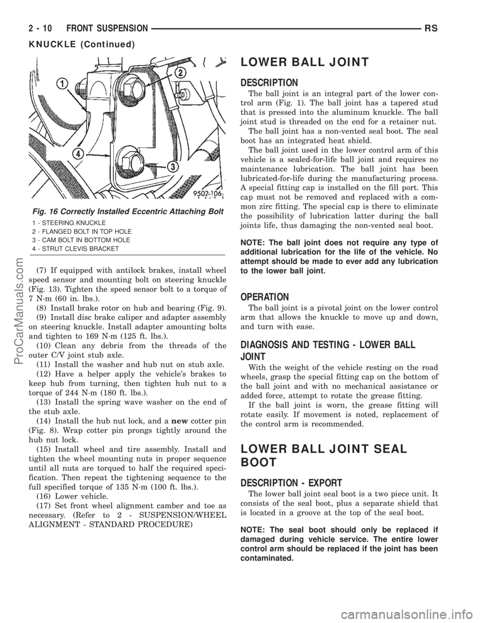
Fig. 16 Correctly Installed Eccentric Attaching Bolt
1 - STEERING KNUCKLE
2 - FLANGED BOLT IN TOP HOLE
3 - CAM BOLT IN BOTTOM HOLE
4 - STRUT CLEVIS BRACKET
2 - 10 FRONT SUSPENSIONRS
KNUCKLE (Continued)
ProCarManuals.com
Page 69 of 2399
WHEEL ALIGNMENT
TABLE OF CONTENTS
page page
WHEEL ALIGNMENT
DESCRIPTION - WHEEL ALIGNMENT.......46
DIAGNOSIS AND TESTING - SUSPENSION
AND STEERING......................49
STANDARD PROCEDURE
STANDARD PROCEDURE - WHEEL
ALIGNMENT.........................51STANDARD PROCEDURE - CURB HEIGHT
MEASUREMENT......................54
STANDARD PROCEDURE - CURB HEIGHT
MEASUREMENT (EXPORT)..............55
SPECIFICATIONS
WHEEL ALIGNMENT...................56
WHEEL ALIGNMENT
DESCRIPTION - WHEEL ALIGNMENT
Vehicle wheel alignment is the positioning of all
interrelated front and rear suspension angles. These
angles affect the handling and steering of the vehicle
when it is in motion. Proper wheel alignment is
essential for efficient steering, good directional stabil-
ity, and proper tire wear.
The method of checking a vehicle's front and rear
wheel alignment varies depending on the manufac-
turer and type of equipment used. The manufactur-
er's instructions should always be followed to ensure
accuracy of the alignment, except when
DaimlerChrysler Corporation's wheel alignment spec-
ifications differ.
On this vehicle, the suspension angles that can be
adjusted are as follows:
²Front Camber (with camber bolt package and
standard procedure)
²Front Toe
Check the wheel alignment and make all wheel
alignment adjustments with the vehicle standing at
its proper curb height specification. Curb height is
the normal riding height of the vehicle. It is mea-
sured from a certain point on the vehicle to the
ground or a designated area while the vehicle is sit-
ting on a flat, level surface. Refer to Curb Height
Measurement in this section for additional informa-
tion.
Typical wheel alignment angles and measurements
are described in the following paragraphs.
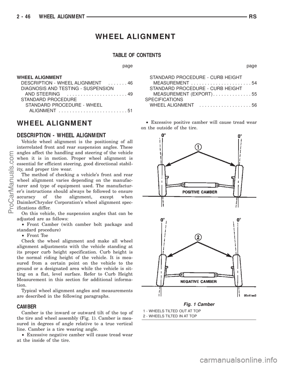
CAMBER
Camber is the inward or outward tilt of the top of
the tire and wheel assembly (Fig. 1). Camber is mea-
sured in degrees of angle relative to a true vertical
line. Camber is a tire wearing angle.
²Excessive negative camber will cause tread wear
at the inside of the tire.²Excessive positive camber will cause tread wear
on the outside of the tire.
Fig. 1 Camber
1 - WHEELS TILTED OUT AT TOP
2 - WHEELS TILTED IN AT TOP
2 - 46 WHEEL ALIGNMENTRS
ProCarManuals.com
Page 70 of 2399

CROSS CAMBER
Cross camber is the difference between left and
right camber. To achieve the cross camber reading,
subtract the right side camber reading from the left.
For example, if the left camber is +0.3É and the right
camber is 0.0É, the cross camber would be +0.3É.
CASTER
Caster is the forward or rearward tilt of the steer-
ing knuckle in reference to the position of the upper
and lower ball joints. Caster is measured in degrees
of angle relative to a true vertical center line. This
line is viewed from the side of the tire and wheel
assembly (Fig. 2).
²Forward tilt (upper ball joint ahead of lower)
results in a negative caster angle.
²Rearward tilt (upper ball joint trailing lower)
results in a positive caster angle.
Although caster does not affect tire wear, a caster
imbalance between the two front wheels may cause
the vehicle to lead to the side with the least positive
caster.
CROSS CASTER
Cross caster is the difference between left and
right caster.
TOE
Toe is the inward or outward angle of the wheels
as viewed from above the vehicle (Fig. 3).
²Toe-in is produced when the front edges of the
wheels on the same axle are closer together than the
rear edges.
²Toe-out is produced when the front edges of the
wheels on the same axle are farther apart than the
rear edges.
Toe-in and toe-out can occur at the front wheels
and the rear wheels.
Toe is measured in degrees or inches. The mea-
surement identifies the amount that the front of the
wheels point inward (toe-in) or outward (toe-out). Toe
is measured at the spindle height. Zero toe means
the front and rear edges of the wheels on the same
axle are equally distant.
Fig. 2 Caster
Fig. 3 Toe
1 - TOE-IN
2 - TOE-OUT
RSWHEEL ALIGNMENT2-47
WHEEL ALIGNMENT (Continued)
ProCarManuals.com
Page 79 of 2399

SPECIFICATIONS
WHEEL ALIGNMENT
NOTE: All specifications are given in degrees.
NOTE: All wheel alignments are to be set at curb
height. (Refer to 2 - SUSPENSION/WHEEL ALIGN-
MENT - STANDARD PROCEDURE)
FRONT WHEEL ALIGNMENT PREFERRED SETTING ACCEPTABLE RANGE
CAMBER +0.10É -0.30É to +0.50É
Cross-Camber (Maximum side-to-side
difference)0.0É 0.50É
CASTER* +2.31É +1.31É to +3.31É
Cross-Caster (Maximum side-to-side difference) 0.0É 1.00É
TOTAL TOE** +0.10É20.10É to +0.30É
Maximum side-to-side difference 0.0É 0.06É
REAR WHEEL ALIGNMENT PREFERRED SETTING ACCEPTABLE RANGE
CAMBER* 0.0É -0.25É to +0.25É
TOTAL TOE* ** 0.0É20.20É to +0.20É
THRUST ANGLE* 0.0É -0.30É to +0.30É
Notes:
* For reference only. These are non-adjustable angles.
** TOTAL TOE is the sum of both left and right wheel toe settings. TOTAL TOE must be equally split between
each front wheel to ensure the steering wheel is centered after setting toe. Positive toe is toe-in and negative toe
is toe-out
2 - 56 WHEEL ALIGNMENTRS
WHEEL ALIGNMENT (Continued)
ProCarManuals.com
Page 165 of 2399
CAUTION: Never use any type of a petroleum-based
fluid in the brake hydraulic system. Use of such
type fluids will result in seal damage of the vehicle
brake hydraulic system causing a failure of the
vehicle brake system. Petroleum based fluids would
be items such as engine oil, transmission fluid,
power steering fluid, etc.
JUNCTION BLOCK
DESCRIPTION - NON-ABS JUNCTION BLOCK
A junction block is used on vehicles that are not
equipped with antilock brakes (ABS). The junction
block mounts in the same location as the integrated
control unit (ICU) does on vehicles equipped with
ABS. This allows for use of the same brake tube con-
figuration on all vehicles. The junction block is
located on the driver's side of the front suspension
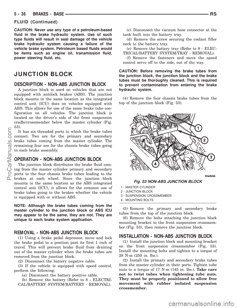
cradle/crossmember below the master cylinder (Fig.
53).
It has six threaded ports to which the brake tubes
connect. Two are for the primary and secondary
brake tubes coming from the master cylinder. The
remaining four are for the chassis brake tubes going
to each brake assembly.
OPERATION - NON-ABS JUNCTION BLOCK
The junction block distributes the brake fluid com-
ing from the master cylinder primary and secondary
ports to the four chassis brake tubes leading to the
brakes at each wheel. Since the junction block
mounts in the same location as the ABS integrated
control unit (ICU), it allows for the common use of
brake tubes going to the brakes whether the vehicle
is equipped with or without ABS.
NOTE: Although the brake tubes coming from the
master cylinder to the junction block or ABS ICU
may appear to be the same, they are not. They are
unique to each brake system application.
REMOVAL - NON-ABS JUNCTION BLOCK
(1) Using a brake pedal depressor, move and lock
the brake pedal to a position past its first 1 inch of
travel. This will prevent brake fluid from draining
out of the master cylinder when the brake tubes are
removed from the junction block.
(2) Disconnect the battery negative cable.
(3) If the vehicle is equipped with speed control,
perform the following:
(a) Disconnect the battery positive cable.
(b) Remove the battery (Refer to 8 - ELECTRI-
CAL/BATTERY SYSTEM/BATTERY - REMOVAL).(c) Disconnect the vacuum hose connector at the
tank built into the battery tray.
(d) Remove the screw securing the coolant filler
neck to the battery tray.
(e) Remove the battery tray (Refer to 8 - ELEC-
TRICAL/BATTERY SYSTEM/TRAY - REMOVAL).
(f) Remove the fasteners and move the speed
control servo off to the side, out of the way.
CAUTION: Before removing the brake tubes from
the junction block, the junction block and the brake
tubes must be thoroughly cleaned. This is required
to prevent contamination from entering the brake
hydraulic system.
(4) Remove the four chassis brake tubes from the
top of the junction block (Fig. 53).
(5) Remove the primary and secondary brake
tubes from the top of the junction block.
(6) Remove the bolts attaching the junction block
mounting bracket to the front suspension crossmem-
ber (Fig. 53), then remove the junction block.INSTALLATION - NON-ABS JUNCTION BLOCK
(1) Install the junction block and mounting bracket
on the front suspension crossmember (Fig. 53).
Install the mounting bolts and tighten to a torque of
28 N´m (250 in. lbs.).
(2) Install the primary and secondary brake tubes
from the master cylinder in their ports. Tighten tube
nuts to a torque of 17 N´m (145 in. lbs.).Take care
not to twist tubes when tightening tube nuts.
They must be properly positioned to allow free
movement with rubber isolated suspension
crossmember.
Fig. 53 NON-ABS JUNCTION BLOCK
1 - MASTER CYLINDER
2 - JUNCTION BLOCK
3 - SUSPENSION CROSSMEMBER
4 - MOUNTING BOLTS
5 - 36 BRAKES - BASERS
FLUID (Continued)
ProCarManuals.com
Page 179 of 2399
(4) Using vacuum line pliers, close off the vacuum
supply hose near the booster, but before the vacuum
gauge, then observe the vacuum gauge.
If the vacuum drop exceeds 1.0 inch Hg (3.3 kPa)
in one minute, repeat the above steps to confirm the
reading. The vacuum loss should be less than 1.0
inch Hg in one minute time span. If the loss is more
than 1.0 inch Hg, replace the power brake booster. If
it is not, continue on with this test.
(5) Remove the pliers from the hose temporarily.
(6) Apply light effort (approximately 15 lbs. of
force) to the brake pedal and hold the pedal steady.
Do not move the pedal once the pressure is applied
or the test results may vary.
(7) Have an assistant reattach the vacuum line
pliers to the vacuum supply hose.
(8) Allow 5 seconds for stabilization, then observe
the vacuum gauge.
If the vacuum drop exceeds 3.0 inches Hg (10 kPa)
in 15 seconds, repeat the above steps to confirm the
reading. The vacuum loss should be less than 3.0
inches Hg in 15 seconds time span. If the loss is
more than 3.0 inches Hg, replace the power brake
booster. If it is not, the booster is not defective.
(9) Remove the pliers and vacuum gauge.
REMOVAL
REMOVAL - LHD
CAUTION: Reserve vacuum in power brake booster
must be pumped down (removed) before removing
master cylinder from booster. This is necessary to
prevent booster from sucking in any contamination
as master cylinder is removed. This can be done
simply by pumping the brake pedal, with the vehi-
cle's engine not running, until a firm feeling brake
pedal is achieved.
(1) With engine not running, pump the brake
pedal until a firm pedal is achieved (4-5 strokes).
(2) Remove negative battery cable terminal from
battery.
(3) Remove positive battery cable terminal from
battery.
(4) Remove battery thermal guard shield.
(5) Remove battery clamp, nut and battery from
the battery tray.
(6) Remove screw securing engine coolant filler
tube to battery tray.
(7) If the vehicle is equipped with speed control,
disconnect the vacuum hose at the vacuum tank built
into the battery tray.
(8) Remove the two nuts and one bolt securing bat-
tery tray in place. Remove battery tray.
(9) If vehicle is equipped with speed control:(a) Disconnect wiring harness connector from
the speed control servo.
(b) Remove the two servo mounting nuts.
(c) Lay speed control servo off to the side, out of
the way.
(10) Remove the wiper module (unit). (Refer to 8 -
ELECTRICAL/WIPERS/WASHERS/WIPER MOD-
ULE - REMOVAL)
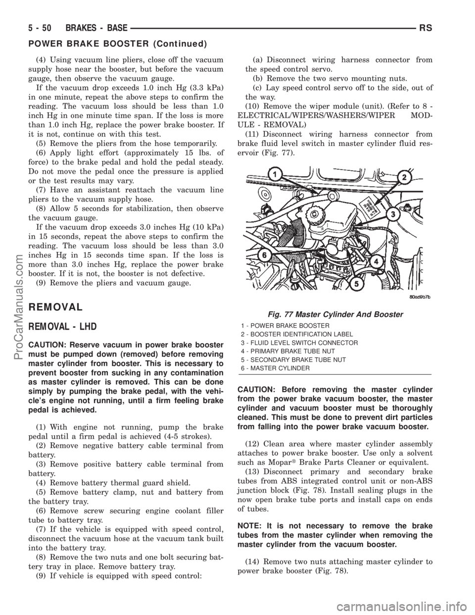
(11) Disconnect wiring harness connector from
brake fluid level switch in master cylinder fluid res-
ervoir (Fig. 77).
CAUTION: Before removing the master cylinder
from the power brake vacuum booster, the master
cylinder and vacuum booster must be thoroughly
cleaned. This must be done to prevent dirt particles
from falling into the power brake vacuum booster.
(12) Clean area where master cylinder assembly
attaches to power brake booster. Use only a solvent
such as MopartBrake Parts Cleaner or equivalent.
(13) Disconnect primary and secondary brake
tubes from ABS integrated control unit or non-ABS
junction block (Fig. 78). Install sealing plugs in the
now open brake tube ports and install caps on ends
of tubes.
NOTE: It is not necessary to remove the brake
tubes from the master cylinder when removing the
master cylinder from the vacuum booster.
(14) Remove two nuts attaching master cylinder to
power brake booster (Fig. 78).
Fig. 77 Master Cylinder And Booster
1 - POWER BRAKE BOOSTER
2 - BOOSTER IDENTIFICATION LABEL
3 - FLUID LEVEL SWITCH CONNECTOR
4 - PRIMARY BRAKE TUBE NUT
5 - SECONDARY BRAKE TUBE NUT
6 - MASTER CYLINDER
5 - 50 BRAKES - BASERS
POWER BRAKE BOOSTER (Continued)
ProCarManuals.com
Page 185 of 2399
the mounting nuts to a torque of 14 N´m (124 in.
lbs.).
(14) Install the battery tray. Install the two nuts
and one bolt attaching the battery tray to the vehicle.
Tighten the bolt and nuts to a torque of 14 N´m (124
in. lbs.).
(15) If vehicle is equipped with speed control, con-
nect the servo vacuum hose to the vacuum tank on
the battery tray.
(16) Install the battery, clamp and mounting nut.
(17) Install the positive battery cable on the bat-
tery.
(18) Install the negative battery cable on the bat-
tery.
(19) Install the battery thermal guard shield.
CAUTION: Do not reuse the original brake lamp
switch. The switch can only be adjusted once. That
is during initial installation of the switch. If the
switch is not adjusted properly or has been
removed for some service, a new switch must be
installed and adjusted.
(20) Remove and replace the brake lamp switch
with a NEW switch. (Refer to 8 - ELECTRICAL/
LAMPS/LIGHTING - EXTERIOR/BRAKE LAMP
SWITCH - REMOVAL), (Refer to 8 - ELECTRICAL/
LAMPS/LIGHTING - EXTERIOR/BRAKE LAMP
SWITCH - INSTALLATION)
(21) Bleed the base brakes as necessary. (Refer to
5 - BRAKES - STANDARD PROCEDURE)
(22) Road test vehicle to ensure proper operation
of the brakes.
PROPORTIONING VALVE
DESCRIPTION - PROPORTIONING VALVE
(HEIGHT SENSING)
NOTE: Only vehicles without antilock brakes (ABS)
have a proportioning valve. Vehicles with ABS uti-
lize electronic brake distribution which is controlled
through the ABS integrated control unit.
Vehicles not equipped with ABS use a height sens-
ing proportioning valve. It is mounted to the body of
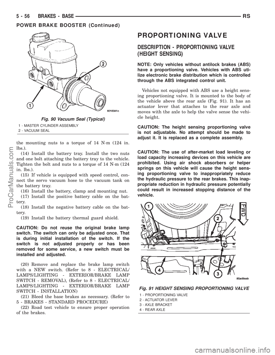
the vehicle above the rear axle (Fig. 91). It has an
actuator lever that attaches to the rear axle and
moves with the axle to help the valve sense the vehi-
cle height.
CAUTION: The height sensing proportioning valve
is not adjustable. No attempt should be made to
adjust it. It is replaced as a complete assembly.
CAUTION: The use of after-market load leveling or
load capacity increasing devices on this vehicle are
prohibited. Using air shock absorbers or helper
springs on this vehicle will cause the height sens-
ing proportioning valve to inappropriately reduce
the hydraulic pressure to the rear brakes. This inap-
propriate reduction in hydraulic pressure potentially
could result in increased stopping distance of the
vehicle.
Fig. 90 Vacuum Seal (Typical)
1 - MASTER CYLINDER ASSEMBLY
2 - VACUUM SEAL
Fig. 91 HEIGHT SENSING PROPORTIONING VALVE
1 - PROPORTIONING VALVE
2 - ACTUATOR LEVER
3 - AXLE BRACKET
4 - REAR AXLE
5 - 56 BRAKES - BASERS
POWER BRAKE BOOSTER (Continued)
ProCarManuals.com
Page 214 of 2399

BRAKES - ABS
TABLE OF CONTENTS
page page
BRAKES - ABS
DESCRIPTION
DESCRIPTION - ANTILOCK BRAKE
SYSTEM............................85
DESCRIPTION - ANTILOCK BRAKE
SYSTEM (EXPORT)....................85
DESCRIPTION - ELECTRONIC VARIABLE
BRAKE PROPORTIONING...............86
DESCRIPTION - TRACTION CONTROL
SYSTEM............................86
OPERATION
OPERATION - ANTILOCK BRAKE SYSTEM . . 86
OPERATION - ELECTRONIC VARIABLE
BRAKE PROPORTIONING...............87
OPERATION - TRACTION CONTROL
SYSTEM............................87
CAUTION
CAUTIONS..........................88
STANDARD PROCEDURE - ANTILOCK BRAKE
SYSTEM BLEEDING...................88
SPECIFICATIONS
ABS FASTENER TORQUE...............89
TONE WHEEL RUNOUT................89
WHEEL SPEED SENSOR AIR GAP........89
FRONT WHEEL SPEED SENSOR
REMOVAL.............................89
INSTALLATION.........................89
REAR WHEEL SPEED SENSOR - AWD
REMOVAL.............................90INSTALLATION.........................90
REAR WHEEL SPEED SENSOR - FWD
REMOVAL.............................91
INSTALLATION.........................91
TONE WHEEL
INSPECTION - TONE WHEEL..............92
TRACTION CONTROL SWITCH
DIAGNOSIS AND TESTING - TRACTION
CONTROL SWITCH....................92
HYDRAULIC/MECHANICAL
OPERATION - HYDRAULIC CIRCUITS AND
VALVES .............................93
HCU (HYDRAULIC CONTROL UNIT)
DESCRIPTION.........................99
OPERATION...........................99
ICU (INTEGRATED CONTROL UNIT)
DESCRIPTION........................100
OPERATION..........................100
REMOVAL
REMOVAL - LHD.....................100
REMOVAL - RHD.....................101
DISASSEMBLY - ICU...................103
ASSEMBLY - ICU......................103
INSTALLATION
INSTALLATION - LHD.................104
INSTALLATION - RHD.................105
BRAKES - ABS
DESCRIPTION
DESCRIPTION - ANTILOCK BRAKE SYSTEM
This section covers the physical and operational
descriptions and the on-car service procedures for the
Mark 20e Antilock Brake System and the Mark 20e
Antilock Brake System with traction control.
The purpose of the antilock brake system (ABS) is
to prevent wheel lockup under braking conditions on
virtually any type of road surface. Antilock braking is
desirable because a vehicle that is stopped without
locking the wheels retains directional stability and
some steering capability. This allows the driver to
retain greater control of the vehicle during braking.
DESCRIPTION - ANTILOCK BRAKE SYSTEM
(EXPORT)
Four-wheel disc antilock brakes are standard on all
models. The Mark 20e antilock brake system is used
on all models. Depending on whether the vehicle is a
left-hand drive (LHD) or right-hand drive (RHD)
model, the integrated control unit (ICU) is located in
one of two locations. On LHD models, the ICU is
mounted above the front suspension cradle/cross-
member below the master cylinder. On RHD models,
the ICU is located behind the front suspension cra-
dle/crossmember on the left side of the vehicle.
RSBRAKES - ABS5-85
ProCarManuals.com