fuse box CHRYSLER VOYAGER 2002 Service Manual
[x] Cancel search | Manufacturer: CHRYSLER, Model Year: 2002, Model line: VOYAGER, Model: CHRYSLER VOYAGER 2002Pages: 2399, PDF Size: 57.96 MB
Page 325 of 2399
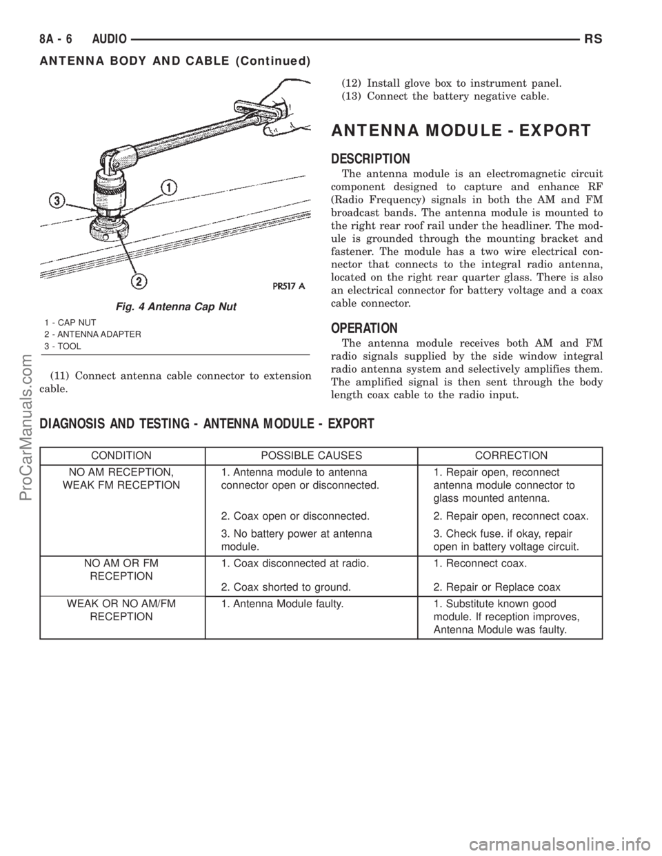
(11) Connect antenna cable connector to extension
cable.(12) Install glove box to instrument panel.
(13) Connect the battery negative cable.
ANTENNA MODULE - EXPORT
DESCRIPTION
The antenna module is an electromagnetic circuit
component designed to capture and enhance RF
(Radio Frequency) signals in both the AM and FM
broadcast bands. The antenna module is mounted to
the right rear roof rail under the headliner. The mod-
ule is grounded through the mounting bracket and
fastener. The module has a two wire electrical con-
nector that connects to the integral radio antenna,
located on the right rear quarter glass. There is also
an electrical connector for battery voltage and a coax
cable connector.
OPERATION
The antenna module receives both AM and FM
radio signals supplied by the side window integral
radio antenna system and selectively amplifies them.
The amplified signal is then sent through the body
length coax cable to the radio input.
DIAGNOSIS AND TESTING - ANTENNA MODULE - EXPORT
CONDITION POSSIBLE CAUSES CORRECTION
NO AM RECEPTION,
WEAK FM RECEPTION1. Antenna module to antenna
connector open or disconnected.1. Repair open, reconnect
antenna module connector to
glass mounted antenna.
2. Coax open or disconnected. 2. Repair open, reconnect coax.
3. No battery power at antenna
module.3. Check fuse. if okay, repair
open in battery voltage circuit.
NO AM OR FM
RECEPTION1. Coax disconnected at radio. 1. Reconnect coax.
2. Coax shorted to ground. 2. Repair or Replace coax
WEAK OR NO AM/FM
RECEPTION1. Antenna Module faulty. 1. Substitute known good
module. If reception improves,
Antenna Module was faulty.
Fig. 4 Antenna Cap Nut
1 - CAP NUT
2 - ANTENNA ADAPTER
3 - TOOL
8A - 6 AUDIORS
ANTENNA BODY AND CABLE (Continued)
ProCarManuals.com
Page 461 of 2399

²Heated Seat Switch- Two heated seat
switches are used per vehicle, one for the driver and
one for the passenger side front seats. The switches
are mounted to in the instrument panel center stack.
Refer to the description of the heated seat switch
later in this section for additional information.
Hard wired circuitry connects the heated seat sys-
tem components to each other through the electrical
system of the vehicle. These hard wired circuits are
integral to several wire harnesses, which are routed
throughout the vehicle and retained by many differ-
ent methods. These circuits may be connected to each
other, to the vehicle electrical system and to the
heated seat system components through the use of a
combination of soldered splices and splice block con-
nectors. Refer to Wiring for complete system wiring
schematics. The wiring information also includes the
proper wire and connector repair procedures, further
details on wire harness routing and retention, as well
as pin-out and location views for the various wire
harness connectors, splices and grounds.
OPERATION
The heated seat system components operate on
battery current received through a fuse in the Inte-
grated Power Module (IPM) on a fused ignition
switch output (run-acc) circuit so that the system willonly operate when the ignition switch is in the On or
Accessory positions. The heated seat system will be
turned Off automatically whenever the ignition
switch is turned to any position except On or Acces-
sory. Also, the heated seat system will not operate
when the surface temperature of the seat cushion
cover at either heated seat sensor is above the
designed temperature set points of the system. The
heated seat system has a self-diagnostic capability.
When certain failures are detected within the heated
seat system, the system will provide a visual indica-
tion of the failure by flashing the Light Emitting
Diode (LED) indicator lamps located in the heated
seat switches. See the owner's manual in the vehicle
glove box for more information on the features, use
and operation of the heated seat system.
DIAGNOSIS AND TESTING - HEATED SEAT
SYSTEM
Refer toWiring Diagramsfor complete wiring
schematics. The wiring information also includes the
proper wire and connector repair procedures, further
details on wire harness routing and retention, as well
as pin-out and location views for the various wire
harness connectors, splices and grounds.
HEATED SEAT SYSTEM DIAGNOSIS
CONDITION POSSIBLE CAUSES CORRECTION
NO HEATED SEAT SWITCH
ILLUMINATION WITH
IGNITION ON (SYSTEM ON)1. Faulty fuse 1. Check heated seat fuse in Integrated Power
Module. Replace fuse, repair short if required.
2. Faulty components 2. Refer to individual Heated Seat System
components for the proper diagnosis and testing
procedures.
3. Ground faulty 3. Check for ground at heated seat switch and
module. Repair, if required.
4. Wiring faulty 4. Check fused ignition switch output (run-acc)
circuits at switch and module. Repair, if required.
8G - 8 HEATED SEAT SYSTEMRS
HEATED SEAT SYSTEM (Continued)
ProCarManuals.com
Page 594 of 2399
²Body Control Module (BCM)- Refer toBody
Control Modulein Electronic Control Modules for
more information.
²Powertrain Control Module (PCM)- Refer to
Powertrain Control Modulein Electronic Control
Modules for more information.
Refer toHeated Seat Systemfor more informa-
tion on the heated seat system. Refer toRemote
Keyless Entry Systemin Power Lock Systems for
more information on the RKE system.
Refer toWiring Diagramsfor complete circuit
diagrams. Following are descriptions, theory of oper-
ation, diagnosis/testing procedures and removal/in-
stallation procedures of the major components in the
memory and power seat systems.
OPERATION
OPERATION - POWER SEAT SYSTEM
The power seat system receives battery current
through fuse #22 in the Intelligent Power Module
and a circuit breaker under the front seats, regard-
less of the ignition switch position.
When a power seat switch control knob or knobs
are actuated, a battery feed and a ground path are
applied through the switch contacts to the appropri-
ate power seat track adjuster motor. The selected
adjuster motor operates to move the seat track
through its drive unit in the selected direction until
the switch is released, or until the travel limit of the
seat track is reached. When the switch is moved in
the opposite direction, the battery feed and ground
path to the motor are reversed through the switch
contacts. This causes the adjuster motor to run in the
opposite direction.
No power seat switch should be held applied in any
direction after the seat track has reached its travel
limit. The power seat track each contain a self-reset-
ting circuit breaker to protect them from overload.
However, consecutive or frequent resetting of the cir-
cuit breaker must not be allowed to continue, or the
motor may be damaged. Refer to the owner's manual
in the vehicle glove box for more information on the
features, use and operation of the power seat system.
OPERATION - MEMORY SYSTEM
The memory system receives battery current
through fuse #22 in the Intelligent Power Module
and the power seat system circuit breaker, located
under each front seat near the rear edge of the seat
cushion pans. The Memory Seat Mirror Module
(MSMM) will drive a maximum of 2 motors at a time
in a given direction. If conflicting directions are
requested, the priority for response will be as follows:
²Seat Track Rearward or Forward²Seat Front Down or Up
²Seat Rear Down or Up
²Recliner Rearward or Forward
The inputs from these switches to the MSMM is a
current limited battery source fed by the MSMM.
This protects the MSMM printed circuit board traces
from acting as fuses. All of these switch contact
inputs to the MSMM are normally closed to ground,
except when actuated.
See the owner's manual in the vehicle glove box for
more information on the features, use and operation
of the memory system. For diagnosis of the MSMM,
the PCI data bus, or the other electronic modules on
the PCI data bus that provide inputs and outputs for
the memory system, the use of a DRBIIItscan tool
and the proper Diagnostic Procedures manual are
recommended.
ELECTRONIC VEHICLE INFORMATION CENTER
The Electronic Vehicle Information Center (EVIC)
serves as the user interface for the memory system.
It displays memory system status messages and pro-
vides the user with the means for enabling and dis-
abling the many customer programmable features
available on the vehicle, including those for the mem-
ory system.
See the owner's manual in the vehicle glove box for
more information on the features, use and operation
of the EVIC. Refer toElectronic Vehicle Informa-
tion Centerin Overhead Console Systems for more
information on the EVIC.
DIAGNOSIS AND TESTING
DIAGNOSIS AND TESTING - POWER SEAT
SYSTEM
Following are tests that will help to diagnose the
hard wired components and circuits of the power seat
system. However, if the vehicle is also equipped with
the optional memory system, these tests may not
prove conclusive in the diagnosis of the driver side
power seat. In order to obtain conclusive testing of
the driver side power seat with the memory system
option, the Programmable Communications Interface
(PCI) data bus network and all of the electronic mod-
ules that provide inputs to, or receive outputs from
the memory system components must be checked.
The most reliable, efficient, and accurate means to
diagnose the driver side power seat with the memory
system option requires the use of a DRB IIItscan
tool and the proper Diagnostic Procedures manual.
The DRB IIItscan tool can provide confirmation that
the PCI data bus is functional, that all of the elec-
tronic modules are sending and receiving the proper
messages on the PCI data bus, and that the memory
RSPOWER SEAT SYSTEM8N-53
POWER SEAT SYSTEM (Continued)
ProCarManuals.com
Page 601 of 2399
DRIVER POWER SEAT TRACK
DESCRIPTION
The eight-way power seat option includes a electri-
cally operated power seat track located under each
front seat. The left side power seat track also pro-
vides the mounting location for the body control mod-
ule on this vehicle. The power seat circuit breakers
are mounted on the rear of each power seat track,
just behind the seat rear trim panel. The lower half
of the power seat track is secured to the floor panel
via four studs and nuts that must be accessed from
the underside of the vehicle. Four bolts secure the
bottom of the seat cushion pan to the upper half of
the power seat track unit. Four additional bolts
secure the seat back frame to the power seat track
unit.
The power seat track unit includes four reversible
electric motors that are secured to the upper half of
the track unit. Each motor moves the seat adjuster
through a combination of worm-drive gearboxes and
screw-type drive units. Each of the four power seat
track motors used on models equipped with the
optional memory system incorporates a position
potentiometer integral to the motor assembly, which
electronically monitors the motor position. This
enables the memory system to function by referenc-
ing the motor positions programmed into the memory
seat/mirror module.
The front and rear of the seat are operated by two
separate vertical adjustment motors. These motors
can be operated independently of each other, tilting
the entire seat assembly forward or rearward; or,
they can be operated in unison by selecting the
proper power seat switch functions, which will raise
or lower the entire seat assembly. A third motor is
the horizontal adjustment motor, which moves the
seat track in the forward and rearward directions.
The forth motor is the recliner adjustment motor,
which moves the seat back in the forward and rear-
ward directions.
The power seat track unit cannot be repaired, and
is serviced only as a complete unit. If any component
in this unit is faulty or damaged, the entire power
seat track unit must be replaced.
OPERATION
When a power seat switch control knob or knobs
are actuated, a battery feed and a ground path are
applied through the switch contacts to the power seat
track or recliner adjuster motor. The selected
adjuster motor operates to move the seat track or
recliner through its drive unit in the selected direc-
tion until the switch is released, or until the travel
limit of the adjuster is reached. When the switch is
moved in the opposite direction, the battery feed andground path to the motor are reversed through the
switch contacts. This causes the adjuster motor to
run in the opposite direction.
No power seat switch should be held applied in any
direction after the adjuster has reached its travel
limit. The power seat adjuster motors each contain a
self-resetting circuit breaker to protect them from
overload. However, consecutive or frequent resetting
of the circuit breaker must not be allowed to con-
tinue, or the motor may be damaged.
See the owner's manual in the vehicle glove box for
more information on the power seat switch functions
and the seat adjusting procedures.
DIAGNOSIS AND TESTING - DRIVER POWER
SEAT TRACK
WARNING: SOME VEHICLES ARE EQUIPPED WITH
SEATBACK MOUNTED AIRBAGS. BEFORE
ATTEMPTING TO DIAGNOSE OR SERVICE ANY
SEAT OR POWER SEAT SYSTEM COMPONENT
YOU MUST FIRST DISCONNECT AND ISOLATE THE
BATTERY NEGATIVE CABLE. THEN WAIT TWO MIN-
UTES FOR THE SYSTEM CAPACITOR TO DIS-
CHARGE BEFORE FURTHER SYSTEM SERVICE.
THIS IS THE ONLY SURE WAY TO DISABLE THE
AIRBAG SYSTEM. FAILURE TO DO SO COULD
RESULT IN ACCIDENTAL AIRBAG DEPLOYMENT
AND POSSIBLE PERSONAL INJURY.
Actuate the power seat switch to move all three
power seat track adjusters in each direction. The
power seat track adjusters should move in each of
the selected directions. If a power seat track adjuster
fails to operate in only one direction, move the
adjuster a short distance in the opposite direction
and test again to be certain that the adjuster is not
at its travel limit. If the power seat track adjuster
still fails to operate in only one direction, refer to
Diagnosis and Testing Power Seat Switchin this
section. If the power seat track adjuster fails to oper-
ate in more than one direction, perform the following
tests. For complete circuit diagrams, refer toWiring
Diagrams.
TESTING POWER SEAT TRACK MOTORS
(1) Check the power seat circuit breaker under the
seat. If OK, go to Step 2. If not OK, replace the
faulty power seat circuit breaker.
(2) Check for battery voltage at the power seat cir-
cuit breaker under the seat. If OK, go to Step 3. If
not OK, repair the open fused B(+) circuit to the fuse
in the Intelligent Power Module as required.
(3) Remove the outboard seat cushion side shield
from the seat. Disconnect the seat wire harness con-
nector from the power seat switch connector recepta-
8N - 60 POWER SEAT SYSTEMRS
ProCarManuals.com
Page 602 of 2399

cle. Check for battery voltage at the fused B(+)
circuit cavity of the power seat wire harness connec-
tor for the power seat switch. If OK, go to Step 4. If
not OK, repair the open fused B(+) circuit to the
power seat circuit breaker under the seat as
required.
(4) Check for continuity between the ground cir-
cuit cavity of the power seat wire harness connector
for the power seat switch and a good ground. There
should be continuity. If OK, go to Step 5. If not OK,
repair the open ground circuit to ground as required.
(5) Test the power seat switch. Refer toDiagnosis
and Testing Power Seat Switchin this section. If
the switch tests OK, test the circuits of the power
seat wire harness between the inoperative power seat
track adjuster motor and the power seat switch for
shorts or opens. If the circuits check OK, replace the
faulty power seat track unit. If the circuits are not
OK, repair the power seat wire harness as required.
REMOVAL
WARNING: SOME VEHICLES ARE EQUIPPED WITH
SEATBACK MOUNTED AIRBAGS. BEFORE
ATTEMPTING TO DIAGNOSE OR SERVICE ANY
SEAT OR POWER SEAT SYSTEM COMPONENT
YOU MUST FIRST DISCONNECT AND ISOLATE THE
BATTERY NEGATIVE CABLE. THEN WAIT TWO MIN-
UTES FOR THE SYSTEM CAPACITOR TO DIS-
CHARGE BEFORE FURTHER SYSTEM SERVICE.
THIS IS THE ONLY SURE WAY TO DISABLE THE
AIRBAG SYSTEM. FAILURE TO DO SO COULD
RESULT IN ACCIDENTAL AIRBAG DEPLOYMENT
AND POSSIBLE PERSONAL INJURY.
(1) Remove the appropriate seat from the vehicle
and place it on a clean work surface(Refer to 23 -
BODY/SEATS/SEAT - REMOVAL).
(2) Remove the Body Control Module retaining
screws.
(3) Disconnect the body control module electrical
connectors and remove the body control module from
the power seat track.
(4) Remove the rear fabric blocker trim panel from
the rear of the front seat.
(5) Remove the seat side cover and power seat
switch as an assembly (Refer to 23 - BODY/SEATS/
SEAT CUSHION SIDE COVERS - REMOVAL).
(6) Disconnect all electrical connectors connecting
the power seat track to the seat assembly.
(7) Pull the seat back trim cover up slightly to
access and remove the two seat back frame mounting
bolts and also remove two seat back recliner bolts.
(8) Remove four seat track mounting bolts from
the seat cushion pan.
(9) Remove the power seat track from the seat.
INSTALLATION
(1) Position the seat cushion on the seat track.
(2) Install the four seat track retaining bolts in the
seat cushion pan. Torque the bolts to 28.5 N´m.
(3) Position the seat back and install the two seat
back frame mounting bolts and the two seat back
recliner bolts. Torque the bolts to 55 N´m.
(4) Route and connect the electrical connectors
between the power seat track and the seat assembly.
(5) Install the seat side cover and power seat
switch as an assembly (Refer to 23 - BODY/SEATS/
SEAT CUSHION SIDE COVERS - INSTALLATION).
(6) Install the rear fabric blocker trim panel on the
rear of the front seat.
(7) Position the body control module and connect
the body control module electrical connectors.
(8) Install the Body Control Module retaining
screws.
(9) Install the seat assembly in the vehicle (Refer
to 23 - BODY/SEATS/SEAT - INSTALLATION).
PASSENGER POWER SEAT
TRACK
DESCRIPTION
The eight-way power seat option includes a electri-
cally operated power seat track unit located under
each front seat. The power seat circuit breaker is
mounted on the rear of the power seat track, just
behind the seat rear trim panel. The lower half of the
power seat track is secured to the floor panel via four
studs and nuts that must be accessed from the
underside of the vehicle. Four bolts secure the bot-
tom of the seat cushion frame to the upper half of the
power seat track unit. Four additional bolts secure
the seat back frame to the power seat track unit.
The power seat track unit includes four reversible
electric motors that are secured to the upper half of
the track unit. Each motor moves the seat adjuster
through a combination of worm-drive gearboxes and
screw-type drive units.
The front and rear of the seat are operated by two
separate vertical adjustment motors. These motors
can be operated independently of each other, tilting
the entire seat assembly forward or rearward; or,
they can be operated in unison by selecting the
proper power seat switch functions, which will raise
or lower the entire seat assembly. A third motor is
the horizontal adjustment motor, which moves the
seat track in the forward and rearward directions.
The forth motor is the recliner adjustment motor,
which moves the seat back in the forward and rear-
ward directions.
RSPOWER SEAT SYSTEM8N-61
DRIVER POWER SEAT TRACK (Continued)
ProCarManuals.com
Page 603 of 2399
The power seat track unit cannot be repaired, and
is serviced only as a complete unit. If any component
in this unit is faulty or damaged, the entire power
seat track unit must be replaced.
OPERATION
When a power seat switch control knob or knobs
are actuated, a battery feed and a ground path are
applied through the switch contacts to the power seat
track or recliner adjuster motor. The selected
adjuster motor operates to move the seat track or
recliner through its drive unit in the selected direc-
tion until the switch is released, or until the travel
limit of the adjuster is reached. When the switch is
moved in the opposite direction, the battery feed and
ground path to the motor are reversed through the
switch contacts. This causes the adjuster motor to
run in the opposite direction.
No power seat switch should be held applied in any
direction after the adjuster has reached its travel
limit. The power seat adjuster motors each contain a
self-resetting circuit breaker to protect them from
overload. However, consecutive or frequent resetting
of the circuit breaker must not be allowed to con-
tinue, or the motor may be damaged.
See the owner's manual in the vehicle glove box for
more information on the power seat switch functions
and the seat adjusting procedures.
DIAGNOSIS AND TESTING - POWER SEAT
TRACK
WARNING: SOME VEHICLES ARE EQUIPPED WITH
SEATBACK MOUNTED AIRBAGS. BEFORE
ATTEMPTING TO DIAGNOSE OR SERVICE ANY
SEAT OR POWER SEAT SYSTEM COMPONENT
YOU MUST FIRST DISCONNECT AND ISOLATE THE
BATTERY NEGATIVE CABLE. THEN WAIT TWO MIN-
UTES FOR THE SYSTEM CAPACITOR TO DIS-
CHARGE BEFORE FURTHER SYSTEM SERVICE.
THIS IS THE ONLY SURE WAY TO DISABLE THE
AIRBAG SYSTEM. FAILURE TO DO SO COULD
RESULT IN ACCIDENTAL AIRBAG DEPLOYMENT
AND POSSIBLE PERSONAL INJURY.
Actuate the power seat switch to move all three
power seat track adjusters in each direction. The
power seat track adjusters should move in each of
the selected directions. If a power seat track adjuster
fails to operate in only one direction, move the
adjuster a short distance in the opposite direction
and test again to be certain that the adjuster is notat its travel limit. If the power seat track adjuster
still fails to operate in only one direction, refer to
Diagnosis and Testing Power Seat Switchin this
section. If the power seat track adjuster fails to oper-
ate in more than one direction, perform the following
tests. For complete circuit diagrams, refer toWiring
Diagrams.
(1) Check the power seat circuit breaker under the
seat. If OK, go to Step 2. If not OK, replace the
faulty power seat circuit breaker.
(2) Check for battery voltage at the power seat cir-
cuit breaker under the seat. If OK, go to Step 3. If
not OK, repair the open fused B(+) circuit to the fuse
in the Intelligent Power Module as required.
(3) Remove the outboard seat cushion side shield
from the seat. Disconnect the seat wire harness con-
nector from the power seat switch connector recepta-
cle. Check for battery voltage at the fused B(+)
circuit cavity of the power seat wire harness connec-
tor for the power seat switch. If OK, go to Step 4. If
not OK, repair the open fused B(+) circuit to the
power seat circuit breaker under the seat as
required.
(4) Check for continuity between the ground cir-
cuit cavity of the power seat wire harness connector
for the power seat switch and a good ground. There
should be continuity. If OK, go to Step 5. If not OK,
repair the open ground circuit to ground as required.
(5) Test the power seat switch. Refer toDiagnosis
and Testing Power Seat Switchin this section. If
the switch tests OK, test the circuits of the power
seat wire harness between the inoperative power seat
track adjuster motor and the power seat switch for
shorts or opens. If the circuits check OK, replace the
faulty power seat track unit. If the circuits are not
OK, repair the power seat wire harness as required.
REMOVAL
WARNING: SOME VEHICLES ARE EQUIPPED WITH
SEATBACK MOUNTED AIRBAGS. BEFORE
ATTEMPTING TO DIAGNOSE OR SERVICE ANY
SEAT OR POWER SEAT SYSTEM COMPONENT
YOU MUST FIRST DISCONNECT AND ISOLATE THE
BATTERY NEGATIVE CABLE. THEN WAIT TWO MIN-
UTES FOR THE SYSTEM CAPACITOR TO DIS-
CHARGE BEFORE FURTHER SYSTEM SERVICE.
THIS IS THE ONLY SURE WAY TO DISABLE THE
AIRBAG SYSTEM. FAILURE TO DO SO COULD
RESULT IN ACCIDENTAL AIRBAG DEPLOYMENT
AND POSSIBLE PERSONAL INJURY.
8N - 62 POWER SEAT SYSTEMRS
PASSENGER POWER SEAT TRACK (Continued)
ProCarManuals.com
Page 894 of 2399
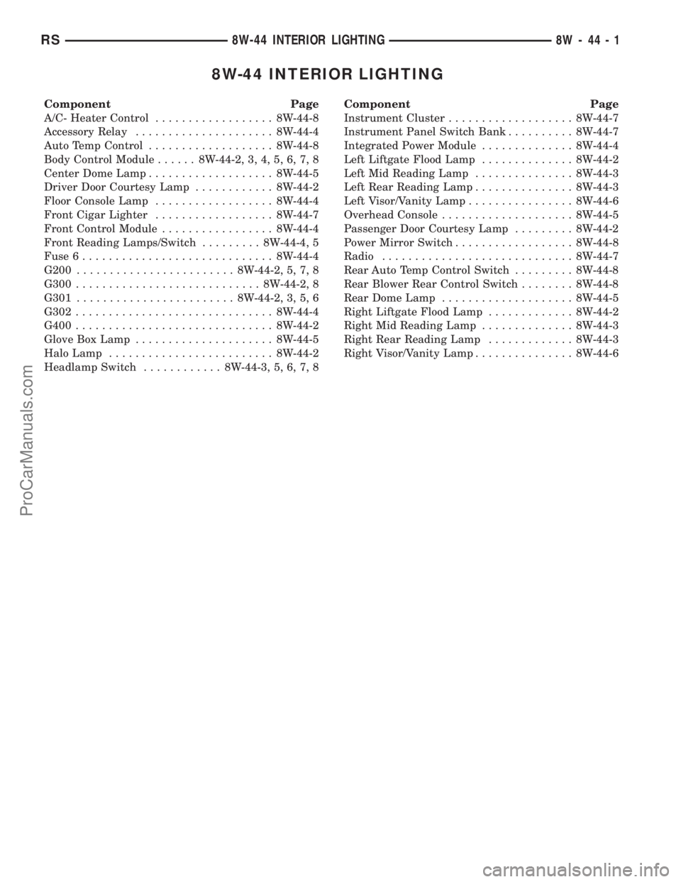
8W-44 INTERIOR LIGHTING
Component Page
A/C- Heater Control.................. 8W-44-8
Accessory Relay..................... 8W-44-4
Auto Temp Control................... 8W-44-8
Body Control Module...... 8W-44-2, 3, 4, 5, 6, 7, 8
Center Dome Lamp................... 8W-44-5
Driver Door Courtesy Lamp............ 8W-44-2
Floor Console Lamp.................. 8W-44-4
Front Cigar Lighter.................. 8W-44-7
Front Control Module................. 8W-44-4
Front Reading Lamps/Switch......... 8W-44-4, 5
Fuse 6............................. 8W-44-4
G200........................ 8W-44-2, 5, 7, 8
G300............................ 8W-44-2, 8
G301........................ 8W-44-2, 3, 5, 6
G302.............................. 8W-44-4
G400.............................. 8W-44-2
Glove Box Lamp..................... 8W-44-5
Halo Lamp......................... 8W-44-2
Headlamp Switch............ 8W-44-3, 5, 6, 7, 8Component Page
Instrument Cluster................... 8W-44-7
Instrument Panel Switch Bank.......... 8W-44-7
Integrated Power Module.............. 8W-44-4
Left Liftgate Flood Lamp.............. 8W-44-2
Left Mid Reading Lamp............... 8W-44-3
Left Rear Reading Lamp............... 8W-44-3
Left Visor/Vanity Lamp................ 8W-44-6
Overhead Console.................... 8W-44-5
Passenger Door Courtesy Lamp......... 8W-44-2
Power Mirror Switch.................. 8W-44-8
Radio............................. 8W-44-7
Rear Auto Temp Control Switch......... 8W-44-8
Rear Blower Rear Control Switch........ 8W-44-8
Rear Dome Lamp.................... 8W-44-5
Right Liftgate Flood Lamp............. 8W-44-2
Right Mid Reading Lamp.............. 8W-44-3
Right Rear Reading Lamp............. 8W-44-3
Right Visor/Vanity Lamp............... 8W-44-6
RS8W-44 INTERIOR LIGHTING8W-44-1
ProCarManuals.com
Page 902 of 2399
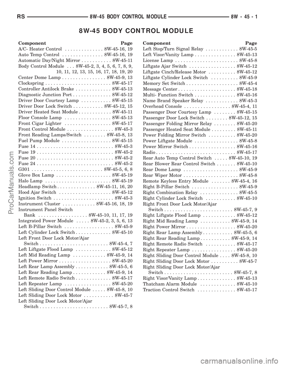
8W-45 BODY CONTROL MODULE
Component Page
A/C- Heater Control.............. 8W-45-16, 19
Auto Temp Control............... 8W-45-16, 19
Automatic Day/Night Mirror........... 8W-45-11
Body Control Module . . . 8W-45-2, 3, 4, 5, 6, 7, 8, 9,
10, 11, 12, 13, 15, 16, 17, 18, 19, 20
Center Dome Lamp................ 8W-45-9, 13
Clockspring........................ 8W-45-17
Controller Antilock Brake............. 8W-45-13
Diagnostic Junction Port.............. 8W-45-12
Driver Door Courtesy Lamp........... 8W-45-15
Driver Door Lock Switch........... 8W-45-12, 15
Driver Heated Seat Module............ 8W-45-11
Floor Console Lamp................. 8W-45-13
Front Cigar Lighter................. 8W-45-17
Front Control Module................. 8W-45-3
Front Reading Lamps/Switch........ 8W-45-8, 13
Fuel Pump Module.................. 8W-45-15
Fuse 14............................ 8W-45-3
Fuse 19............................ 8W-45-2
Fuse 20............................ 8W-45-2
Fuse 24............................ 8W-45-2
G301.......................... 8W-45-5, 6, 8
Glove Box Lamp.................... 8W-45-19
Halo Lamp........................ 8W-45-19
Headlamp Switch.............. 8W-45-11, 16, 20
Hood Ajar Switch................... 8W-45-12
Ignition Switch...................... 8W-45-3
Instrument Cluster............ 8W-45-16, 18, 19
Instrument Panel Switch
Bank.................. 8W-45-10, 11, 17, 19
Integrated Power Module..... 8W-45-2, 3, 5, 6, 13
Left B-Pillar Switch.................. 8W-45-9
Left Cylinder Lock Switch............. 8W-45-10
Left Front Door Lock Motor/Ajar
Switch......................... 8W-45-4, 7
Left Liftgate Flood Lamp............. 8W-45-12
Left Mid Reading Lamp............ 8W-45-9, 14
Left Power Mirror................... 8W-45-20
Left Rear Lamp Assembly............ 8W-45-5, 6
Left Rear Reading Lamp............ 8W-45-9, 14
Left Remote Radio Switch............. 8W-45-17
Left Repeater Lamp................. 8W-45-20
Left Sliding Door Control Module..... 8W-45-8, 10
Left Sliding Door Lock Motor........... 8W-45-7
Left Sliding Door Lock Motor/Ajar
Switch......................... 8W-45-7, 8Component Page
Left Stop/Turn Signal Relay............ 8W-45-5
Left Visor/Vanity Lamp............... 8W-45-13
License Lamp....................... 8W-45-8
Liftgate Ajar Switch................. 8W-45-12
Liftgate Cinch/Release Motor.......... 8W-45-12
Liftgate Cylinder Lock Switch.......... 8W-45-9
Memory Set Switch................... 8W-45-4
Message Center..................... 8W-45-18
Multi- Function Switch............... 8W-45-16
Name Brand Speaker Relay............ 8W-45-3
Overhead Console................. 8W-45-4, 11
Passenger Door Courtesy Lamp........ 8W-45-15
Passenger Door Lock Switch........ 8W-45-12, 15
Passenger Folding Mirror Relay........ 8W-45-20
Passenger Heated Seat Module......... 8W-45-11
Power Folding Mirror Switch.......... 8W-45-20
Power Liftgate Module................ 8W-45-8
Power Mirror Switch................. 8W-45-16
Radio............................. 8W-45-17
Rear Auto Temp Control Switch..... 8W-45-10, 19
Rear Blower Rear Control Switch....... 8W-45-10
Rear Dome Lamp.................... 8W-45-9
Rear Wiper Motor.................... 8W-45-8
Remote Keyless Entry Module....... 8W-45-4, 16
Right B-Pillar Switch................. 8W-45-9
Right Combination Relay.............. 8W-45-5
Right Cylinder Lock Switch........... 8W-45-10
Right Front Door Lock Motor/Ajar
Switch......................... 8W-45-7, 9
Right Liftgate Flood Lamp............ 8W-45-12
Right Mid Reading Lamp........... 8W-45-9, 14
Right Power Mirror.................. 8W-45-20
Right Rear Lamp Assembly........... 8W-45-5, 6
Right Rear Reading Lamp........... 8W-45-9, 14
Right Remote Radio Switch........... 8W-45-17
Right Repeater Lamp................ 8W-45-20
Right Sliding Door Control Module.... 8W-45-8, 10
Right Sliding Door Lock Motor.......... 8W-45-7
Right Sliding Door Lock Motor/Ajar
Switch......................... 8W-45-7, 8
Right Visor/Vanity Lamp.............. 8W-45-13
Thatcham Alarm Module............. 8W-45-10
Traction Control Switch.............. 8W-45-17
RS8W-45 BODY CONTROL MODULE8W-45-1
ProCarManuals.com
Page 1044 of 2399

BODY CONTROL MODULE C4 - BLACK/GRAY 34 WAY
CAV CIRCUIT FUNCTION
1 E18 20OR/LB (POWER MIRRORS) PANEL LAMPS DRIVER (MIRROR SWITCH)
2 E12 20OR/GY PANEL LAMPS DRIVER (HVAC)
3 E19 20OR/BR PANEL LAMPS DRIVER (HEADLAMP SWITCH)
4 D9 20WT/GY RKE MODULE PROGRAM ENABLE
5 G150 20VT/BR INSTRUMENT CLUSTER WAKE UP SENSE
6- -
7 P162 20LG/DG (BUILT-UP-EXPORT) PASSENGER FOLDING MIRROR RELAY CONTROL
8 G69 20VT/WT (VTSS) VTSS INDICATOR DRIVER
9 L161 20WT/LG LEFT TURN INDICATOR DRIVER
10 F504 20GY/PK FUSED IGNITION SWITCH OUTPUT (RUN)
11 E14 20OR/TN PANEL LAMPS DRIVER (RADIO)
12 E13 20OR/YL PANEL LAMPS DRIVER (INSTRUMENT CLUSTER)
13 X920 20GY/OR RADIO CONTROL MUX RETURN
14 G900 20VT/OR IGNITION SWITCH SENSE RETURN
15 - -
16 - -
17 L160 20WT/TN RIGHT TURN INDICATOR DRIVER
18 M26 20YL/DB HALO LAMP DRIVER
19 - -
20 - -
21 - -
22 G902 20VT/OR MULTI-FUNCTION SWITCH MUX RETURN
23 - -
24 - -
25 - -
26 M28 20YL/TN GLOVE BOX LAMP DRIVER
27 - -
28 - -
29 - -
30 - -
31 G96 20VT/DG REMOTE KEYLESS ENTRY INTERFACE
32 B27 20DG/WT TRACTION CONTROL SWITCH SENSE
33 P136 20TN/YL (BUILT-UP-EXPORT) FOLDING MIRROR SWITCH SENSE
34 G26 20VT/OR CHIME DRIVER
RS8W-80 CONNECTOR PIN-OUTS8W-80-13
ProCarManuals.com
Page 1094 of 2399

FUEL PRESSURE SOLENOID (DIESEL) - BLACK 2 WAY
CAV CIRCUIT FUNCTION
1 K342 16BR/WT ECM/PCM RELAY OUTPUT
2 K87 16BR FUEL PRESSURE SOLENOID CONTROL
FUEL PUMP MODULE - LT. GRAY 4 WAY
CAV CIRCUIT FUNCTION
1 Z201 16BK/OR (GAS) GROUND
2 Z201 18BK/OR (RHD/DIESEL) GROUND
2 Z201 20BK/DB (LHD/DIESEL) (GAS) GROUND
3 N4 18DB/WT FUEL LEVEL SENSOR SIGNAL
4 N1 16DB/OR (GAS) FUEL PUMP RELAY OUTPUT
GENERATOR - BLACK 2 WAY
CAV CIRCUIT FUNCTION
1 K342 16BR/WT (DIESEL) ECM/PCM RELAY OUTPUT
1 K342 16BR/WT (GAS) AUTOMATIC SHUT DOWN RELAY OUTPUT
2 K20 14BR/GY (DIESEL) GENERATOR FIELD CONTROL
2 K20 18BR/GY (GAS) GENERATOR FIELD CONTROL
GLOVE BOX LAMP - BLUE 2 WAY
CAV CIRCUIT FUNCTION
1 M28 20YL/TN GLOVE BOX LAMP DRIVER
2 Z328 20BK/TN GROUND
GLOW PLUG RELAY (DIESEL) - BLACK 4 WAY
CAV CIRCUIT FUNCTION
1 A202 10RD/WT FUSED B(+)
2 K152 20DB/WT GLOW PLUG RELAY CONTROL
3 K342 16BR/WT ECM/PCM RELAY OUTPUT
4 K154 10BR/OR GLOW PLUG RELAY OUTPUT
HALO LAMP - BLUE 2 WAY
CAV CIRCUIT FUNCTION
1 Z326 20BK/OR GROUND
2 M26 20YL/DB HALO LAMP DRIVER
RS8W-80 CONNECTOR PIN-OUTS8W-80-63
ProCarManuals.com