manual radio set CHRYSLER VOYAGER 2002 Service Manual
[x] Cancel search | Manufacturer: CHRYSLER, Model Year: 2002, Model line: VOYAGER, Model: CHRYSLER VOYAGER 2002Pages: 2399, PDF Size: 57.96 MB
Page 141 of 2399
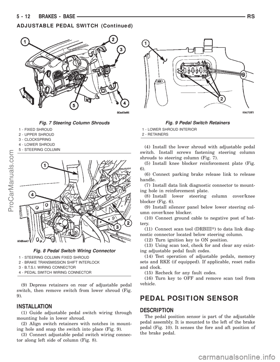
(9) Depress retainers on rear of adjustable pedal
switch, then remove switch from lower shroud (Fig.
9).
INSTALLATION
(1) Guide adjustable pedal switch wiring through
mounting hole in lower shroud.
(2) Align switch retainers with notches in mount-
ing hole and snap the switch into place (Fig. 9).
(3) Connect adjustable pedal switch wiring connec-
tor along left side of column (Fig. 8).(4) Install the lower shroud with adjustable pedal
switch. Install screws fastening steering column
shrouds to steering column (Fig. 7).
(5) Install knee blocker reinforcement plate (Fig.
6).
(6) Connect parking brake release link to release
handle.
(7) Install data link diagnostic connector to mount-
ing hole in reinforcement plate.
(8) Install lower steering column cover/knee
blocker (Fig. 6).
(9) Install silencer panel below lower steering col-
umn cover/knee blocker.
(10) Connect ground cable to negative post of bat-
tery.
(11) Connect scan tool (DRBIIIt) to data link diag-
nostic connector located below steering column.
(12) Turn ignition key to ON position.
(13) Using scan tool, check for and clear any exist-
ing adjustable pedal fault codes.
(14) Test operation of adjustable pedals, memory
sets and RKE (if equipped). If applicable, reset radio
and clock.
(15) Recheck for any fault codes.
(16) Turn key to OFF and remove scan tool from
vehicle.
PEDAL POSITION SENSOR
DESCRIPTION
The pedal position sensor is part of the adjustable
pedal assembly. It is mounted to the left of the brake
pedal (Fig. 10). It senses the fore and aft position of
the brake pedal.
Fig. 7 Steering Column Shrouds
1 - FIXED SHROUD
2 - UPPER SHROUD
3 - CLOCKSPRING
4 - LOWER SHROUD
5 - STEERING COLUMN
Fig. 8 Pedal Switch Wiring Connector
1 - STEERING COLUMN FIXED SHROUD
2 - BRAKE TRANSMISSION SHIFT INTERLOCK
3 - B.T.S.I. WIRING CONNECTOR
4 - PEDAL SWITCH WIRING CONNECTOR
Fig. 9 Pedal Switch Retainers
1 - LOWER SHROUD INTERIOR
2 - RETAINERS
5 - 12 BRAKES - BASERS
ADJUSTABLE PEDAL SWITCH (Continued)
ProCarManuals.com
Page 142 of 2399
DIAGNOSIS AND TESTING - PEDAL POSITION
SENSOR
Refer to Appropriate Diagnostic Information.
REMOVAL
(1) Remove battery ground cable terminal from
battery negative post and isolate.
(2) Under instrument panel, remove silencer panel
below lower steering column cover.
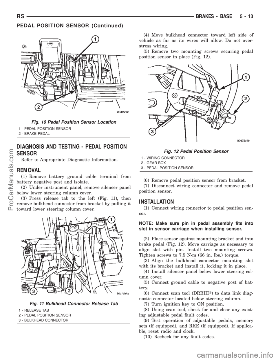
(3) Press release tab to the left (Fig. 11), then
remove bulkhead connector from bracket by pulling it
toward lower steering column cover.(4) Move bulkhead connector toward left side of
vehicle as far as its wires will allow. Do not over-
stress wiring.
(5) Remove two mounting screws securing pedal
position sensor in place (Fig. 12).
(6) Remove pedal position sensor from bracket.
(7) Disconnect wiring connector and remove pedal
position sensor.
INSTALLATION
(1) Connect wiring connector to pedal position sen-
sor.
NOTE: Make sure pin in pedal assembly fits into
slot in sensor carriage when installing sensor.
(2) Place sensor against mounting bracket and into
brake pedal (Fig. 12). Move carriage as necessary to
align slot with pin. Install two mounting screws.
Tighten screws to 7.5 N´m (66 in. lbs.) torque.
(3) Align the bulkhead connector mounting slot
with its bracket and install it, locking it in place.
(4) Install silencer panel below lower steering col-
umn cover.
(5) Connect ground cable to negative post of bat-
tery.
(6) Connect scan tool (DRBIIIt) to data link diag-
nostic connector located below steering column.
(7) Turn ignition key to ON position.
(8) Using scan tool, check for and clear any exist-
ing adjustable pedal fault codes.
(9) Test operation of adjustable pedals, memory
sets (if equipped), and RKE (if equipped). If applica-
ble, reset radio and clock.
(10) Recheck for any fault codes.
Fig. 10 Pedal Position Sensor Location
1 - PEDAL POSITION SENSOR
2 - BRAKE PEDAL
Fig. 11 Bulkhead Connector Release Tab
1 - RELEASE TAB
2 - PEDAL POSITION SENSOR
3 - BULKHEAD CONNECTOR
Fig. 12 Pedal Position Sensor
1 - WIRING CONNECTOR
2 - GEAR BOX
3 - PEDAL POSITION SENSOR
RSBRAKES - BASE5-13
PEDAL POSITION SENSOR (Continued)
ProCarManuals.com
Page 176 of 2399
(27) Install lower steering column cover/knee
blocker (Fig. 62).
(28) Install silencer panel below lower steering col-
umn cover/knee blocker.
NOTE: When reconnecting the battery on a vehicle
that has had the airbag module removed, the fol-
lowing procedure should be used.
(29) Reconnect ground cable to negative post of
battery in following manor:
(a) Connect scan tool (DRBIIIt) to data link
diagnostic connector located below steering column.
(b) Turn ignition key to ON position. Exit vehi-
cle with scan tool leaving scan tool harness
plugged in.
(c) Ensuring that there are no occupants in vehi-
cle, connect ground (-) cable to the negative post of
the battery.
(d) Using scan tool, read and record any airbag
fault codes. Refer to Appropriate Diagnostic Infor-
mation if any faults are found.
(e) Through drivers open window, Reach around
back of steering wheel (between steering wheel and
instrument cluster) and turn ignition key to OFF,
then back ON while observing instrument cluster
airbag indicator lamp. It should go on for six to
eight seconds, then go out. This action indicates
that airbag system is functioning normally. If air-
bag indicator lamp fails to light, blinks on and off,
or goes on and stays on, there is an airbag system
malfunction. Refer to Appropriate Diagnostic Infor-
mation to diagnose the system malfunction.
(30) Using scan tool (DRBIIIt), check for and clear
any existing adjustable pedal fault codes. The adjust-
able pedal system is now activated.
(31) Turn key to OFF and remove scan tool from
vehicle.
(32) Test operation of adjustable pedals, memory
seats (if equipped), RKE (if equipped), and all func-
tions that are steering column operated. If applica-
ble, reset the radio and the clock.
(33) Road test the vehicle to ensure proper opera-
tion of the steering and brake systems.
PEDAL TORQUE SHAFT - RHD
REMOVAL
(1) Remove the instrument panel. (Refer to 23 -
BODY/INSTRUMENT PANEL/INSTRUMENT
PANEL ASSEMBLY - REMOVAL)
(2) Remove the HVAC housing. (Refer to 24 -
HEATING & AIR CONDITIONING/DISTRIBUTION/
HVAC HOUSING - REMOVAL)
(3) Remove the retaining clip at the torque shaft
end of the brake pedal-to-torque shaft link. Removethe link from the torque shaft. Discard the retaining
clip. It is not to be reused. Replace with a new clip
when reassembled.
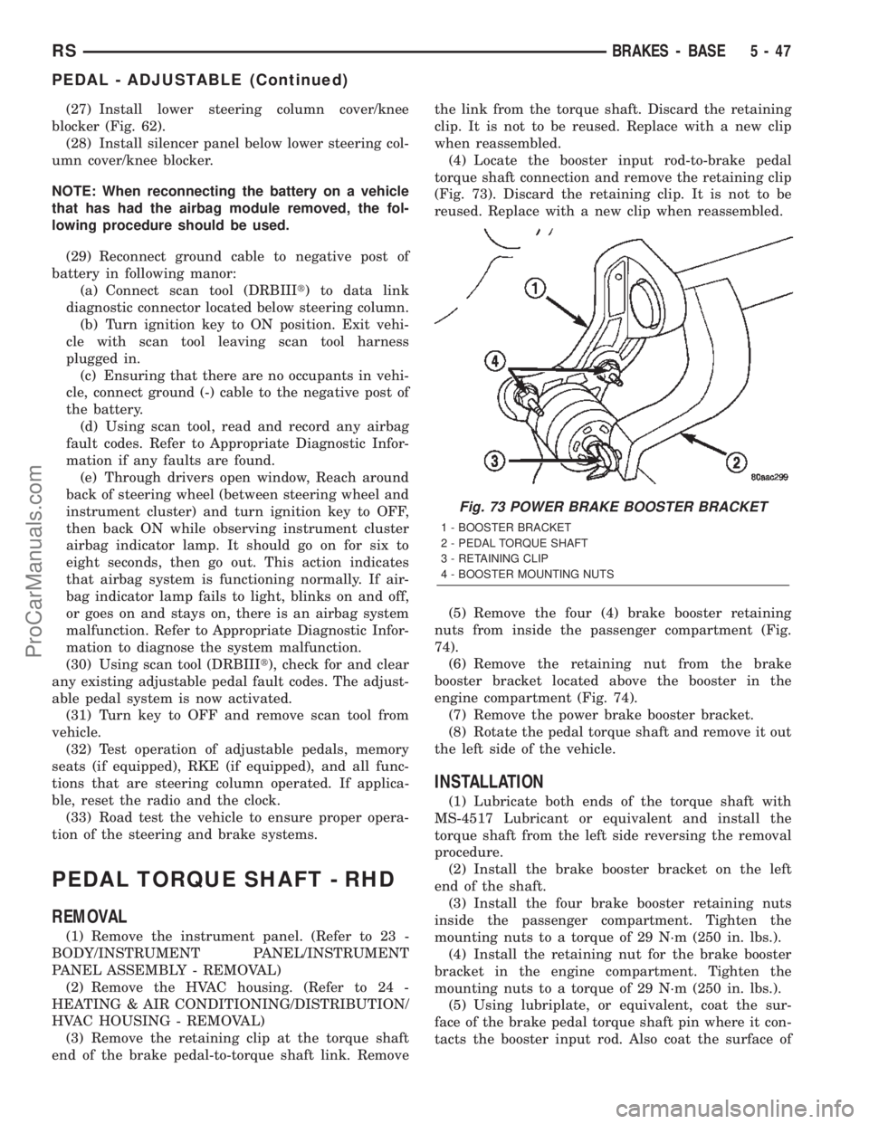
(4) Locate the booster input rod-to-brake pedal
torque shaft connection and remove the retaining clip
(Fig. 73). Discard the retaining clip. It is not to be
reused. Replace with a new clip when reassembled.
(5) Remove the four (4) brake booster retaining
nuts from inside the passenger compartment (Fig.
74).
(6) Remove the retaining nut from the brake
booster bracket located above the booster in the
engine compartment (Fig. 74).
(7) Remove the power brake booster bracket.
(8) Rotate the pedal torque shaft and remove it out
the left side of the vehicle.
INSTALLATION
(1) Lubricate both ends of the torque shaft with
MS-4517 Lubricant or equivalent and install the
torque shaft from the left side reversing the removal
procedure.
(2) Install the brake booster bracket on the left
end of the shaft.
(3) Install the four brake booster retaining nuts
inside the passenger compartment. Tighten the
mounting nuts to a torque of 29 N´m (250 in. lbs.).
(4) Install the retaining nut for the brake booster
bracket in the engine compartment. Tighten the
mounting nuts to a torque of 29 N´m (250 in. lbs.).
(5) Using lubriplate, or equivalent, coat the sur-
face of the brake pedal torque shaft pin where it con-
tacts the booster input rod. Also coat the surface of
Fig. 73 POWER BRAKE BOOSTER BRACKET
1 - BOOSTER BRACKET
2 - PEDAL TORQUE SHAFT
3 - RETAINING CLIP
4 - BOOSTER MOUNTING NUTS
RSBRAKES - BASE5-47
PEDAL - ADJUSTABLE (Continued)
ProCarManuals.com
Page 320 of 2399
AUDIO
TABLE OF CONTENTS
page page
AUDIO
DESCRIPTION..........................1
OPERATION............................1
DIAGNOSIS AND TESTING - AUDIO..........1
ANTENNA BODY AND CABLE
DESCRIPTION..........................4
OPERATION............................4
DIAGNOSIS AND TESTING - ANTENNA BODY
AND CABLE..........................4
REMOVAL.............................4
INSTALLATION..........................5
ANTENNA MODULE - EXPORT
DESCRIPTION..........................6
OPERATION............................6
DIAGNOSIS AND TESTING - ANTENNA
MODULE - EXPORT....................6
REMOVAL.............................7
INSTALLATION..........................7
CD CHANGER
DESCRIPTION..........................7
OPERATION............................7
REMOVAL.............................7
INSTALLATION..........................7
INSTRUMENT PANEL ANTENNA CABLE
REMOVAL.............................8INSTALLATION..........................8
QUARTER GLASS INTEGRAL ANTENNA -
EXPORT
DESCRIPTION..........................8
OPERATION............................8
DIAGNOSIS AND TESTING - QUARTER
GLASS INTEGRAL ANTENNA - EXPORT.....8
RADIO
DIAGNOSIS AND TESTING - RADIO..........9
REMOVAL.............................9
INSTALLATION.........................10
RADIO NOISE SUPPRESSION COMPONENTS
DESCRIPTION.........................10
OPERATION...........................10
REMOTE SWITCHES
DESCRIPTION.........................11
OPERATION...........................11
DIAGNOSIS AND TESTING - REMOTE
SWITCHES..........................11
REMOVAL.............................12
INSTALLATION.........................12
SPEAKER
DIAGNOSIS AND TESTING - SPEAKER......12
REMOVAL.............................13
INSTALLATION.........................14
AUDIO
DESCRIPTION
There are four different system combinations avail-
able on this model. The available radio options are:
²AM/FM Cassette
²AM/FM Compact Disc with Compact Disc
changer controls
²AM/FM Cassette with single Compact Disc
Player and Compact Disc changer controls
²AM/FM Cassette with Compact Disc changer
controls
²AM/FM Cassette with Compact Disc player, rear
seat audio system and Compact Disc changer con-
trols.
The rear seat audio system allows passengers to
listen to a different music source, through head-
phones, other than what is playing through the vehi-
cles speaker system. A remote control is provided for
functions such as changing stations, tracks, disc and
modes while listening to rear seat audio. The radiomust be turned ON to use the rear seat audio sys-
tem.
All factory installed radio receivers are stereo Elec-
tronically Tuned Radios (ETR) and include and elec-
tronic digital clock function.
OPERATION
Operating instructions for the factory installed
audio systems can be found in the Owner's Manual
provided with this vehicle.
DIAGNOSIS AND TESTING - AUDIO
Any diagnosis of the Audio system should
begin with the use of the DRB IIItdiagnostic
tool. For information on the use of the DRB
IIIt, refer to the appropriate Diagnostic Service
Manual.
Refer to the appropriate wiring information. The
wiring information includes wiring diagrams, proper
wire and connector repair procedures, details of wire
harness routing and retention, connector pin-out
RSAUDIO8A-1
ProCarManuals.com
Page 322 of 2399

CONDITION POSSIBLE CAUSE CORRECTION
2. GROUND FAULTY. 2. CHECK FOR CONTINUITY BETWEEN RADIO CHASSIS AND
A KNOWN GOOD GROUND. THERE SHOULD BE
CONTINUITY. REPAIR GROUND, IF REQUIRED.
3. RADIO FAULTY. 3. EXCHANGE OR REPLACE RADIO, IF REQUIRED.
4. POOR ANTENNA
CONNECTION AT
RADIO OR IN LINE.4. SEAT CONNECTOR.
NO/POOR TAPE
OPERATION.1. FAULTY TAPE. 1. INSERT KNOWN GOOD TAPE AND TEST OPERATION.
2. FOREIGN OBJECTS
BEHIND TAPE DOOR.2. REMOVE FOREIGN OBJECTS AND TEST OPERATION.
3. DIRTY CASSETTE
TAPE HEAD.3. CLEAN HEAD WITH MOPAR CASSETTE HEAD CLEANER.
4. FAULTY TAPE DECK. 4. EXCHANGE OR REPLACE RADIO, IF REQUIRED.
NO COMPACT
DISC
OPERATION1. FAULTY CD. 1. INSERT KNOWN GOOD CD AND TEST OPERATION.
2. FOREIGN MATERIAL
ON CD.2. CLEAN CD AND TEST OPERATION.
3. CONDENSATION ON
CD OR OPTICS.3. ALLOW TEMPERATURE OF VEHICLE INTERIOR TO
STABILIZE AND TEST OPERATION.
4. FAULTY CD PLAYER. 4. EXCHANGE OR REPLACE RADIO, IF REQUIRED.
HEADPHONES
WILL NOT HOLD
A CHANNEL OR
HAVE STATIC1. WEAK BATTERIES IN
THE HEADPHONES.1. REPLACE BATTERIES.
2. CLOSENESS TO
RADIO TRANSMITTER
SUCH AS A RADIO
TOWER, AIRPORT
TRANSMITTER OR
SOME MOBILE
RADIOS.2. MOVE TO AN AREA AWAY FREE FROM THESE
CONDITIONS.
REMOTE
CONTROL
INOPERATIVE1. WEAK BATTERIES IN
THE REMOTE
CONTROL.1. REPLACE BATTERIES.
2. OPERATION
CONSTRAINT OF
SYSTEM2. MAKE SURE THAT REAR AUDIO IS IN A DIFFERENT MODE
THAN FRONT SPEAKERS. REMOTE CONTROL WILL NOT
WORK WHEN BOTH ARE IN THE SAME MODE.
RSAUDIO8A-3
AUDIO (Continued)
ProCarManuals.com
Page 328 of 2399
RADIO
DIAGNOSIS AND TESTING - RADIO
WARNING: ON VEHICLES EQUIPPED WITH AIR-
BAGS, REFER TO ELECTRICAL, RESTRAINTS
BEFORE ATTEMPTING ANY STEERING WHEEL,
STEERING COLUMN, OR INSTRUMENT PANEL
COMPONENT DIAGNOSIS OR SERVICE. FAILURE
TO TAKE THE PROPER PRECAUTIONS COULD
RESULT IN ACCIDENTAL AIRBAG DEPLOYMENT
AND POSSIBLE PERSONAL INJURY.
Any diagnosis of the Audio system should
begin with the use of the DRB IIItdiagnostic
tool. For information on the use of the DRB
IIIt, refer to the appropriate Diagnostic Service
Manual.
Refer to the appropriate wiring information. The
wiring information includes wiring diagrams, proper
wire and connector repair procedures, details of wire
harness routing and retention, connector pin-out
information and location views for the various wire
harness connectors, splices and grounds.
If the vehicle is equipped with remote radio
switches located on the back of the steering wheel
spokes, and the problem being diagnosed is related to
one of the symptoms listed below, be certain to check
the remote radio switches and circuits as described
in this group, prior to attempting radio diagnosis or
repair.
²Stations changing with no remote radio switch
input
²Radio memory presets not working properly
²Volume changes with no remote radio switch
input
²Remote radio switch buttons taking on other
functions
²CD player skipping tracks
²Remote radio switch inoperative.
CAUTION: The speaker output of the radio is a
ªfloating groundº system. Do not allow any speaker
lead to short to ground, as damage to the radio
may result.
(1) Check the fuse(s) in the junction block and the
Integrated Power Module (IPM). If OK, go to Step 2.
If not OK, repair the shorted circuit or component as
required and replace the faulty fuse(s).
(2) Check for battery voltage at the fuse in the
(IPM). If OK, go to Step 3. If not OK, repair the open
circuit to the battery as required.
(3) Turn the ignition switch to the ON position.
Check for battery voltage at the fuse in the junction
block. If OK, go to Step 4. If not OK, repair the open
circuit to the ignition switch as required.(4) Turn the ignition switch to the OFF position.
Remove the radio, but do not unplug the wire har-
ness connectors. Check for continuity between the
radio chassis and a good ground. There should be
continuity. If OK, go to Step 5. If not OK, repair the
open radio chassis ground circuit as required.
(5) Connect the battery negative cable. Turn the
ignition switch to the ON position. Check for battery
voltage at the fused ignition switch output circuit
cavity of the radio wire harness connector. If OK, go
to Step 6. If not OK, repair the open circuit as
required.
(6) Turn the ignition switch to the OFF position.
Check for battery voltage at the fused B(+) circuit
cavity of the radio wire harness connector. If OK,
replace the faulty radio. If not OK, repair the open
circuit to the Ignition-Off Draw (IOD) fuse as
required.
REMOVAL
(1) Disconnect and isolate the battery negative
cable.
(2) Remove cup holder.
(3) Remove trim panel above cupholder by pulling
straight out.
(4) Remove center instrument panel trim panel.
(5) Remove screws holding radio to instrument
panel.
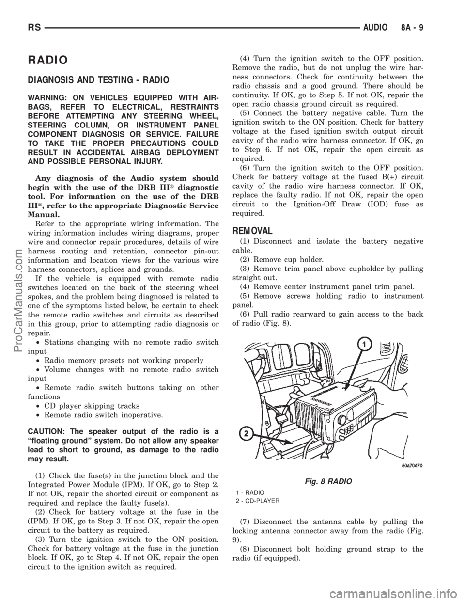
(6) Pull radio rearward to gain access to the back
of radio (Fig. 8).
(7) Disconnect the antenna cable by pulling the
locking antenna connector away from the radio (Fig.
9).
(8) Disconnect bolt holding ground strap to the
radio (if equipped).
Fig. 8 RADIO
1 - RADIO
2 - CD-PLAYER
RSAUDIO8A-9
ProCarManuals.com
Page 330 of 2399
REMOTE SWITCHES
DESCRIPTION
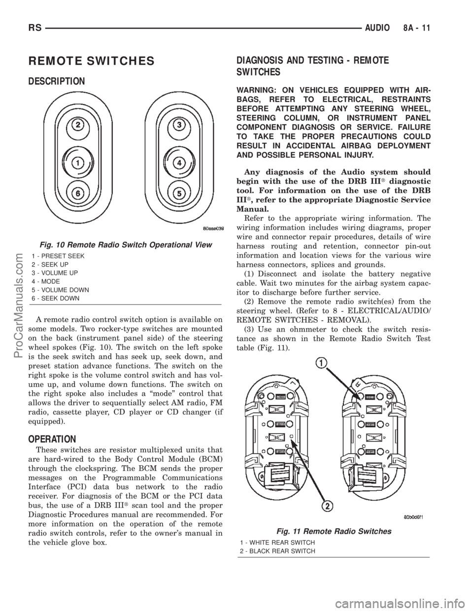
A remote radio control switch option is available on
some models. Two rocker-type switches are mounted
on the back (instrument panel side) of the steering
wheel spokes (Fig. 10). The switch on the left spoke
is the seek switch and has seek up, seek down, and
preset station advance functions. The switch on the
right spoke is the volume control switch and has vol-
ume up, and volume down functions. The switch on
the right spoke also includes a ªmodeº control that
allows the driver to sequentially select AM radio, FM
radio, cassette player, CD player or CD changer (if
equipped).
OPERATION
These switches are resistor multiplexed units that
are hard-wired to the Body Control Module (BCM)
through the clockspring. The BCM sends the proper
messages on the Programmable Communications
Interface (PCI) data bus network to the radio
receiver. For diagnosis of the BCM or the PCI data
bus, the use of a DRB IIItscan tool and the proper
Diagnostic Procedures manual are recommended. For
more information on the operation of the remote
radio switch controls, refer to the owner's manual in
the vehicle glove box.
DIAGNOSIS AND TESTING - REMOTE
SWITCHES
WARNING: ON VEHICLES EQUIPPED WITH AIR-
BAGS, REFER TO ELECTRICAL, RESTRAINTS
BEFORE ATTEMPTING ANY STEERING WHEEL,
STEERING COLUMN, OR INSTRUMENT PANEL
COMPONENT DIAGNOSIS OR SERVICE. FAILURE
TO TAKE THE PROPER PRECAUTIONS COULD
RESULT IN ACCIDENTAL AIRBAG DEPLOYMENT
AND POSSIBLE PERSONAL INJURY.
Any diagnosis of the Audio system should
begin with the use of the DRB IIItdiagnostic
tool. For information on the use of the DRB
IIIt, refer to the appropriate Diagnostic Service
Manual.
Refer to the appropriate wiring information. The
wiring information includes wiring diagrams, proper
wire and connector repair procedures, details of wire
harness routing and retention, connector pin-out
information and location views for the various wire
harness connectors, splices and grounds.
(1) Disconnect and isolate the battery negative
cable. Wait two minutes for the airbag system capac-
itor to discharge before further service.
(2) Remove the remote radio switch(es) from the
steering wheel. (Refer to 8 - ELECTRICAL/AUDIO/
REMOTE SWITCHES - REMOVAL).
(3) Use an ohmmeter to check the switch resis-
tance as shown in the Remote Radio Switch Test
table (Fig. 11).
Fig. 10 Remote Radio Switch Operational View
1 - PRESET SEEK
2 - SEEK UP
3 - VOLUME UP
4 - MODE
5 - VOLUME DOWN
6 - SEEK DOWN
Fig. 11 Remote Radio Switches
1 - WHITE REAR SWITCH
2 - BLACK REAR SWITCH
RSAUDIO8A-11
ProCarManuals.com
Page 331 of 2399

REMOTE RADIO SWITCH TEST
SWITCH POSITION RESISTANCE
VOLUME UP 7320 OHMS
VOLUME DOWN 1210 OHMS
SEEK UP 4530 OHMS
SEEK DOWN 2050 OHMS
PRE-SET STATION ADVANCE 10 OHMS
NOTE: The right remote radio switch back is white
in color. The left switch back is black in color. The
right/left remote radio switch orientation is with the
steering wheel installed, and driver in drivers seat.
(4) If the switch resistance checks OK, go to Step
5. If not OK, replace the faulty switch.
(5) Check for continuity between the ground cir-
cuit cavity of the switch wire harness connector and
a good ground. There should be continuity. If OK, go
to Step 6. If not OK, repair the open circuit as
required.
(6) Unplug the 24-way white wire harness connec-
tor from the Body Control Module (BCM). Check for
continuity between the radio control circuit cavity of
the remote radio switch wire harness connector and a
good ground. There should be no continuity. If OK, go
to Step 7. If not OK, repair the short circuit as
required.
(7) Check for continuity between the radio control
circuit cavities of the remote radio switch wire har-
ness connector and the BCM wire harness connector.
There should be continuity. If OK, refer to the proper
Diagnostic Procedures manual to test the BCM and
the PCI data bus. If not OK, repair the open circuit
as required.
REMOVAL
WARNING: ON VEHICLES EQUIPPED WITH AIR-
BAGS, REFER TO ELECTRICAL, RESTRAINTS
BEFORE ATTEMPTING ANY STEERING WHEEL,
STEERING COLUMN, OR INSTRUMENT PANEL
COMPONENT DIAGNOSIS OR SERVICE. FAILURE
TO TAKE THE PROPER PRECAUTIONS COULD
RESULT IN ACCIDENTAL AIRBAG DEPLOYMENT
AND POSSIBLE PERSONAL INJURY.
(1) Disconnect and isolate the battery negative
cable. Wait two minutes for the airbag system capac-
itor to discharge before further service.
(2) Remove the driver side airbag module from the
vehicle. Refer to ELECTRICAL/RESTRAINTS/
DRIVER AIR BAG.(3) Remove the steering wheel from the steering
column. Refer to STEERING/COLUMN/STEERING
WHEEL.
(4) Unplug the wire harness connector from the
remote radio switch (s).
(5) Remove three screws securing steering wheel
rear cover.
(6) Remove the remote radio switch from the steer-
ing wheel by depressing tabs on each side of each
switch.
NOTE: The right remote radio switch back is white
in color. The left switch back is black in color. The
right/left remote radio switch orientation is with the
steering wheel installed, and driver in drivers seat.
INSTALLATION
WARNING: ON VEHICLES EQUIPPED WITH AIR-
BAGS, REFER TO ELECTRICAL, RESTRAINTS
BEFORE ATTEMPTING ANY STEERING WHEEL,
STEERING COLUMN, OR INSTRUMENT PANEL
COMPONENT DIAGNOSIS OR SERVICE. FAILURE
TO TAKE THE PROPER PRECAUTIONS COULD
RESULT IN ACCIDENTAL AIRBAG DEPLOYMENT
AND POSSIBLE PERSONAL INJURY.
(1)
Install remote radio switch to the steering wheel.
(2) Install three screws securing steering wheel
rear cover.
(3) Connect the wire harness to the remote radio
switch.
(4) Install the steering wheel. Refer to STEERING/
COLUMN/STEERING WHEEL.
(5) Install the driver side airbag module. Refer to
ELECTRICAL/RESTRAINTS/DRIVER AIRBAG.
(6) Connect the battery negative cable.
SPEAKER
DIAGNOSIS AND TESTING - SPEAKER
WARNING: DISABLE THE AIRBAG SYSTEM BEFORE
ATTEMPTING ANY STEERING WHEEL, STEERING
COLUMN, SEAT BELT TENSIONER, SIDE AIRBAG,
OR INSTRUMENT PANEL COMPONENT DIAGNOSIS
OR SERVICE. DISCONNECT AND ISOLATE THE BAT-
TERY NEGATIVE (GROUND) CABLE, THEN WAIT
TWO MINUTES FOR THE AIRBAG SYSTEM CAPACI-
TOR TO DISCHARGE BEFORE PERFORMING FUR-
THER DIAGNOSIS OR SERVICE. THIS IS THE ONLY
SURE WAY TO DISABLE THE AIRBAG SYSTEM.
FAILURE TO TAKE THE PROPER PRECAUTIONS
COULD RESULT IN ACCIDENTAL AIRBAG DEPLOY-
MENT AND POSSIBLE PERSONAL INJURY.
8A - 12 AUDIORS
REMOTE SWITCHES (Continued)
ProCarManuals.com
Page 346 of 2399
(4) Install the battery in the vehicle. Refer to the
procedure in Battery Systems.
(5) Connect the positive and negative battery
cables.
(6) Using the DRB IIIt, under ªFRONT CON-
TROL MODULEº then ªMISCº program the EQ
curve of the radio into the Front Control Module.
Refer to the appropriate diagnostic manual.
NOTE: If the vehicle is not equipped with Name
Brand Speakers (Infinity, etc.) or Headlamp Washers
the DRB IIITmust be used to Disable the appropri-
ate relays in the Intelligent Power Module Assembly.
HEATED SEAT MODULE
DESCRIPTION
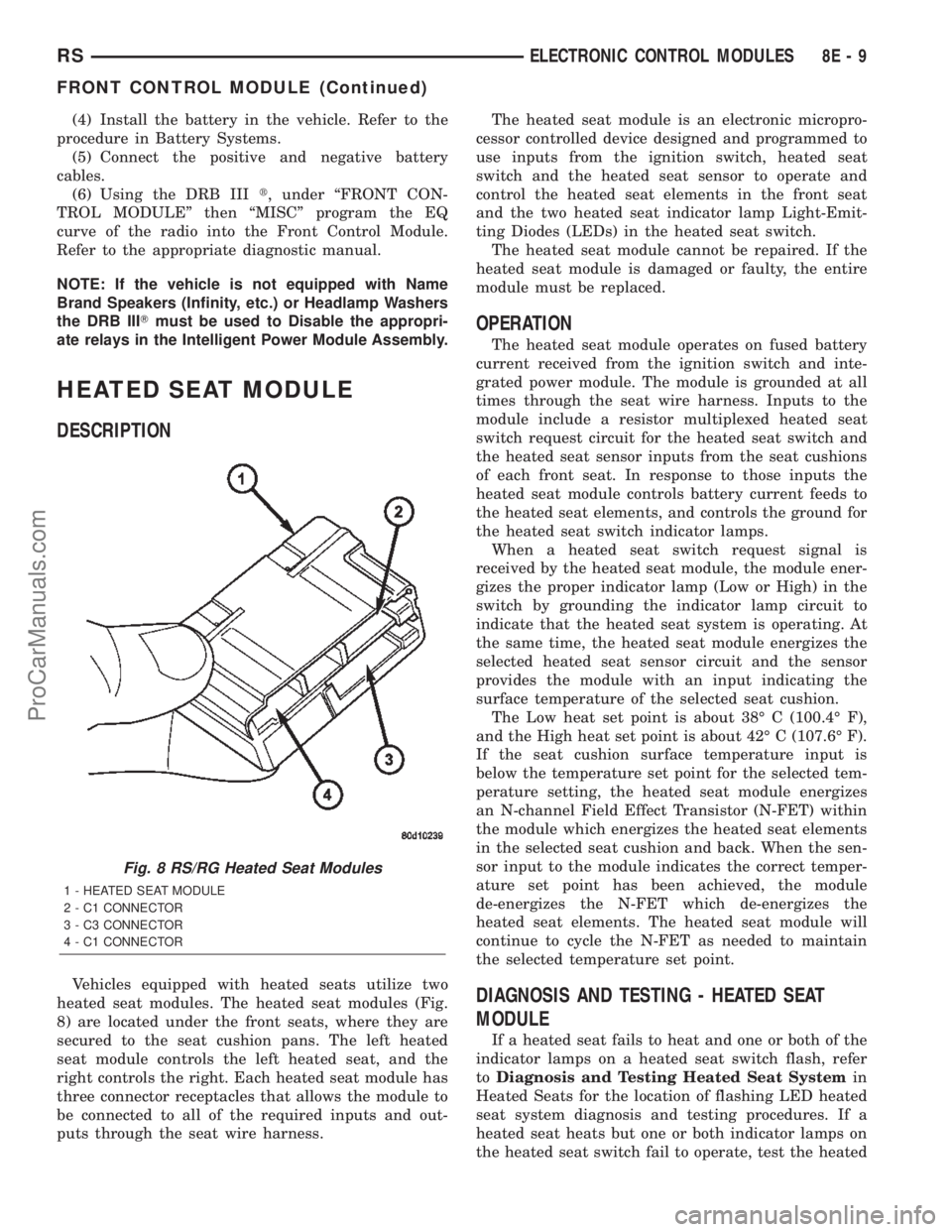
Vehicles equipped with heated seats utilize two
heated seat modules. The heated seat modules (Fig.
8) are located under the front seats, where they are
secured to the seat cushion pans. The left heated
seat module controls the left heated seat, and the
right controls the right. Each heated seat module has
three connector receptacles that allows the module to
be connected to all of the required inputs and out-
puts through the seat wire harness.The heated seat module is an electronic micropro-
cessor controlled device designed and programmed to
use inputs from the ignition switch, heated seat
switch and the heated seat sensor to operate and
control the heated seat elements in the front seat
and the two heated seat indicator lamp Light-Emit-
ting Diodes (LEDs) in the heated seat switch.
The heated seat module cannot be repaired. If the
heated seat module is damaged or faulty, the entire
module must be replaced.
OPERATION
The heated seat module operates on fused battery
current received from the ignition switch and inte-
grated power module. The module is grounded at all
times through the seat wire harness. Inputs to the
module include a resistor multiplexed heated seat
switch request circuit for the heated seat switch and
the heated seat sensor inputs from the seat cushions
of each front seat. In response to those inputs the
heated seat module controls battery current feeds to
the heated seat elements, and controls the ground for
the heated seat switch indicator lamps.
When a heated seat switch request signal is
received by the heated seat module, the module ener-
gizes the proper indicator lamp (Low or High) in the
switch by grounding the indicator lamp circuit to
indicate that the heated seat system is operating. At
the same time, the heated seat module energizes the
selected heated seat sensor circuit and the sensor
provides the module with an input indicating the
surface temperature of the selected seat cushion.
The Low heat set point is about 38É C (100.4É F),
and the High heat set point is about 42É C (107.6É F).
If the seat cushion surface temperature input is
below the temperature set point for the selected tem-
perature setting, the heated seat module energizes
an N-channel Field Effect Transistor (N-FET) within
the module which energizes the heated seat elements
in the selected seat cushion and back. When the sen-
sor input to the module indicates the correct temper-
ature set point has been achieved, the module
de-energizes the N-FET which de-energizes the
heated seat elements. The heated seat module will
continue to cycle the N-FET as needed to maintain
the selected temperature set point.
DIAGNOSIS AND TESTING - HEATED SEAT
MODULE
If a heated seat fails to heat and one or both of the
indicator lamps on a heated seat switch flash, refer
toDiagnosis and Testing Heated Seat Systemin
Heated Seats for the location of flashing LED heated
seat system diagnosis and testing procedures. If a
heated seat heats but one or both indicator lamps on
the heated seat switch fail to operate, test the heated
Fig. 8 RS/RG Heated Seat Modules
1 - HEATED SEAT MODULE
2 - C1 CONNECTOR
3 - C3 CONNECTOR
4 - C1 CONNECTOR
RSELECTRONIC CONTROL MODULES8E-9
FRONT CONTROL MODULE (Continued)
ProCarManuals.com
Page 373 of 2399
these sensor inputs to adjust fuel quantity and fuel
injector timing.
Limp-In Mode
If there is a fault detected with the accelerator
pedal position sensor, the ECM will set the engine
speed at 1100 RPM.
Overspeed Detection Mode
If the ECM detects engine RPM that exceeds 5200
RPM, the ECM will set a DTC in memory and illu-
minate the MIL until the DTC is cleared.
After-Run Mode
The ECM transfers RAM information to ROM and
performs an Input/Output state check.
MONITORED CIRCUITS
The ECM is able to monitor and identify most
driveability related trouble conditions. Some circuits
are directly monitored through ECM feedback cir-
cuitry. In addition, the ECM monitors the voltage
state of some circuits and compares those states with
expected values. Other systems are monitored indi-
rectly when the ECM conducts a rationality test to
identify problems. Although most subsytems of the
engine control module are either directly or indirectly
monitored, there may be occasions when diagnostic
trouble codes are not immediately identified. For a
trouble code to set, a specific set of conditions must
occur and unless these conditions occur, a DTC will
not set.
DIAGNOSTIC TROUBLE CODES
Each diagnostic trouble code (DTC) is diagnosed by
following a specific procedure. The diagnostic test
procedure contains step-by-step instruction for deter-
mining the cause of the DTC as well as no trouble
code problems. Refer to the appropriate Diesel Pow-
ertrain Diagnostic Manual for more information.
HARD CODE
A DTC that comes back within one cycle of the
ignition key is a hard code. This means that the
problem is current every time the ECM/SKIM checks
that circuit or function. Procedures in this manual
verify if the DTC is a hard code at the beginning of
each test. When the fault is not a hard code, an
intermittent test must be performed. NOTE: If the
DRBIIItdisplays faults for multiple components (i.e.
ECT, VSS, IAT sensors) identify and check the
shared circuits for possible problems before continu-
ing (i.e. sensor grounds or 5-volt supply circuits).
Refer to the appropriate schematic to identify shared
circuits. Refer to the appropriate Diesel Powertrain
Diagnostic Manual for more information.INTERMITTENT CODE
A DTC that is not current every time the ECM/
SKIM checks the circuit or function is an intermit-
tent code. Most intermittent DTCs are caused by
wiring or connector problems. Problems that come
and go like this are the most difficult to diagnose;
they must be looked for under specific conditions that
cause them.NOTE: Electromagnetic (radio)
interference can cause an intermittent system
malfunction.This interference can interrupt com-
munication between the ignition key transponder and
the SKIM. The following checks may assist you in
identifying a possible intermittent problem:
²Visually inspect the related wire harness connec-
tors. Look for broken, bent, pushed out or corroded
terminals.
²Visually inspect the related wire harness. Look
for chafed, pierced or partially broken wire.
²Refer to hotlines or technical service bulletins
that may apply. Refer to the appropriate Diesel Pow-
ertrain Diagnostic Manual for more information.
ECM DIAGNOSTIC TROUBLE CODES
IMPORTANT NOTE: Before replacing the ECM for
a failed driver, control circuit or ground circuit, be
sure to check the related component/circuit integrity
for failures not detected due to a double fault in the
circuit. Most ECM driver/control circuit failures are
caused by internal failures to components (i.e. relays
and solenoids) and shorted circuits (i.e. sensor pull-
ups, drivers and ground circuits). These faults are
difficult to detect when a double fault has occurred
and only one DTC has set. If the DRBIIItdisplays
faults for multiple components (i.e.VSS, ECT, Batt
Temp, etc.) identify and check the shared circuits for
possible problems before continuing (i.e. sensor
grounds or 5-volt supply circuits). Refer to the appro-
priate wiring diagrams to identify shared circuits.
Refer to the appropriate Diesel Powertrain Diagnos-
tic Manual for more information.
STANDARD PROCEDURE - PCM/ECM/SKIM
PROGRAMMING - DIESEL
NOTE: Before replacing the PCM/ECM for a failed
driver, control circuit or ground circuit, be sure to
check the related component/circuit integrity for
failures not detected due to a double fault in the cir-
cuit. Most PCM/ECM driver/control circuit failures
are caused by internal component failures (i.e. relay
and solenoids) and shorted circuits (i.e. pull-ups,
drivers and switched circuits). These failures are
difficult to detect when a double fault has occurred
and only one DTC has set.
8Ea - 2 ELECTRONIC CONTROL MODULESRG
ENGINE CONTROL MODULE (Continued)
ProCarManuals.com