timing belt CHRYSLER VOYAGER 2002 Service Manual
[x] Cancel search | Manufacturer: CHRYSLER, Model Year: 2002, Model line: VOYAGER, Model: CHRYSLER VOYAGER 2002Pages: 2399, PDF Size: 57.96 MB
Page 281 of 2399

WATER PUMP - 2.4L
DESCRIPTION
The water pump has a cast aluminum body and
housing with a stamped steel impeller. The water
pump bolts directly to the block (Fig. 23). The cylin-
der block to water pump seal is provided by a rubber
O-ring. The water pump is driven by the engine tim-
ing belt.
OPERATION
The water pump is the heart of the cooling system.
The coolant is pumped through the engine block, cyl-
inder head, heater core, and radiator.
REMOVAL
(1) Disconnect negative cable from battery.
(2) Raise vehicle on a hoist.
(3) Remove the right inner splash shield.
(4) Remove the accessory drive belts (Refer to 7 -
COOLING/ACCESSORY DRIVE/DRIVE BELTS -
REMOVAL).
(5) Drain the cooling system (Refer to 7 - COOL-
ING - STANDARD PROCEDURE).
(6) Support engine from the bottom and remove
right engine mount. (Refer to 9 - ENGINE/ENGINE
MOUNTING/RIGHT MOUNT - REMOVAL).(7) Remove right engine mount bracket (Fig. 24).
(8) Remove the timing belt (Refer to 9 - ENGINE/
VALVE TIMING/TIMING BELT AND SPROCKET(S)
- REMOVAL).
(9) Remove timing belt idler pulley.
(10) Hold camshaft sprocket with Special tool
C-4687 and adaptor C-4687-1 while removing bolt.
Remove both cam sprockets.
(11) Remove the timing belt rear cover (Refer to 9
- ENGINE/VALVE TIMING/TIMING BELT COV-
ER(S) - REMOVAL).
(12) Remove the generator and bracket (Fig. 24).
(13) Remove water pump to engine attaching
screws (Fig. 25).
CLEANING
Clean gasket mating surfaces as necessary.
INSPECTION
Replace water pump body assembly if it has any of
these defects:
(1) Cracks or damage on the body.
(2) Coolant leaks from the shaft seal, evident by
wet coolant traces on the pump body.
(3) Loose or rough turning bearing.
(4) Impeller rubs either the pump body or the
engine block.
(5) Impeller loose or damaged.
(6) Sprocket or sprocket flange loose or damaged.
INSTALLATION
(1) Install new O-ring gasket in water pump body
O-ring locating groove (Fig. 26).
CAUTION: Make sure O-ring is properly seated in
water pump groove before tightening screws. An
improperly located O-ring may be damaged and
cause a coolant leak.
(2) Assemble pump body to block and tighten
screws to 12 N´m (105 in. lbs.) (Fig. 25). Pressurize
cooling system to 103.4 Kpa (15 psi) with pressure
tester and check water pump shaft seal and O-ring
for leaks.
(3) Rotate pump by hand to check for freedom of
movement.
(4) Install the timing belt rear cover (Refer to 9 -
ENGINE/VALVE TIMING/TIMING BELT COVER(S)
- INSTALLATION).
(5) Install camshaft sprockets and torque bolts to
101 N´m (75 ft. lbs.) while holding camshaft sprocket
with Special tool C-4687 and adaptor C-4687-1.
(6) Install timing belt idler pulley and torque
mounting bolt to 61 N´m (45 ft. lbs.).
Fig. 23 Water Pump
1 - CYLINDER BLOCK
2 - WATER PUMP
7 - 32 ENGINERS
ProCarManuals.com
Page 283 of 2399

(7) Install the timing belt (Refer to 9 - ENGINE/
VALVE TIMING/TIMING BELT AND SPROCKET(S)
- INSTALLATION).
(8) Install the generator mount bracket. (Fig. 24)
(9) Install the generator.
(10) Install right engine mount bracket and engine
mount (Refer to 9 - ENGINE/ENGINE MOUNTING/
RIGHT MOUNT - INSTALLATION).
(11) Fill the cooling system (Refer to 7 - COOLING
- STANDARD PROCEDURE).
(12) Install the accessory drive belts (Refer to 7 -
COOLING/ACCESSORY DRIVE/DRIVE BELTS -
INSTALLATION).
(13) Lower vehicle and connect battery cable.
WATER PUMP - 3.3/3.8L
DESCRIPTION
The water pump has a die-cast aluminum body
and a plastic impeller. It bolts directly to the timing
chain case cover, using a rubber seal for sealing (Fig.
27). It is driven by the accessory drive belt.
OPERATION
The water pump is the heart of the cooling system.
The coolant is pumped through the engine block, cyl-
inder head, heater core, and radiator.
REMOVAL
(1) Drain the cooling system. (Refer to 7 - COOL-
ING - STANDARD PROCEDURE)
(2) Remove the accessory drive belt shield.
(3) Remove the accessory drive belt. (Refer to 7 -
COOLING/ACCESSORY DRIVE/DRIVE BELTS -
REMOVAL)
(4) Remove water pump pulley bolts (Fig. 27).
NOTE: To remove the water pump pulley, it MUST
first be positioned between water pump housing
and drive hub. The pulley can then be removed with
the water pump assembly.
(5) Rotate pulley until openings in pulley align
with water pump drive hub spokes (Fig. 28). Move
pulley inward between pump housing and hub (Fig.
28).
(6) Position pulley to allow access to water pump
mounting bolts. Remove water pump mounting bolts
(Fig. 29).
(7) Remove water pump with the pulley loosely
positioned between hub and the pump body.
(8) Remove and discard the seal.
Fig. 27 Water Pump - 3.3/3.8L Engine
1 - WATER PUMP
2 - PULLEY - WATER PUMP
3 - BOLT - PULLEY
4 - BOLT - WATER PUMP
5 - SEAL - WATER PUMP
Fig. 28 Water Pump Pulley Positioning
1 - HUB - WATER PUMP
2 - PULLEY - WATER PUMP
7 - 34 ENGINERS
WATER PUMP - 2.4L (Continued)
ProCarManuals.com
Page 285 of 2399

(5) Rotate pump by hand to check for freedom of
movement.
(6) Install the accessory drive belt. (Refer to 7 -
COOLING/ACCESSORY DRIVE/DRIVE BELTS -
INSTALLATION)
(7) Install drive belt shield.
(8) Fill the cooling system. (Refer to 7 - COOLING
- STANDARD PROCEDURE)
WATER PUMP INLET TUBE -
2.4L
DESCRIPTION
The 2.4L engine uses a metal tube to connect the
engine block to the lower radiator hose and heater
return (Fig. 32). The tube has an O-ring for block to
tube sealing and bolts attach the tube to the engine
block.
REMOVAL
(1) Drain the cooling system. (Refer to 7 - COOL-
ING - STANDARD PROCEDURE)
(2) Remove radiator upper hose to access the hose
connections at the inlet tube.
(3) Remove radiator lower (Fig. 7) and heater
hoses from the inlet tube (Fig. 33).
(4) Remove the two fasteners that hold the inlet
tube to the block.
(5) Rotate tube while removing the tube from the
engine block.
INSTALLATION
(1) Inspect the O-ring for damage before installing
the tube into the cylinder block (Fig. 32).(2) Lube O-ring with coolant and install inlet tube
into the cylinder block opening (Fig. 32).
(3) Install the two inlet tube fasteners and tighten
to 12 N´m (105 in. lbs.).
(4) Connect the radiator lower hose (Fig. 7) and
heater hose to inlet tube (Fig. 33).
(5) Install the radiator upper hose.
(6) Fill the cooling system. (Refer to 7 - COOLING
- STANDARD PROCEDURE)
WATER PUMP INLET TUBE -
3.3/3.8L
REMOVAL
(1) Drain the cooling system. (Refer to 7 - COOL-
ING - STANDARD PROCEDURE)
(2) Raise vehicle on hoist and remove the belt
splash shield.
(3) Remove the radiator lower hose from inlet tube
(Fig. 34).
(4) Remove the oil cooler outlet/heater return hose
from inlet tube (only if equipped with engine oil
cooler) (Fig. 35).
(5) Remove the inlet tube bolts (Fig. 36).
(6) Remove the inlet tube (Fig. 36). Discard the
O-ring seal.
INSTALLATION
(1) Clean the inlet tube O-ring sealing surfaces on
the timing cover housing and tube.
(2) Apply MopartDielectric Grease or equivalent
to the O-ring before installation.
(3) Position new O-ring seal on inlet tube (Fig. 36).
Fig. 32 Water Pump Inlet TubeÐ2.4L Engine
1 - O-RING
2 - WATER PUMP INLET TUBE
Fig. 33 Water Pump Inlet Tube Hose Connections
1 - WATER PUMP INLET TUBE
2 - HOSE - HEATER RETURN
3 - COOLANT INLET
7 - 36 ENGINERS
WATER PUMP - 3.3/3.8L (Continued)
ProCarManuals.com
Page 286 of 2399

(4) Install the inlet tube (Fig. 36). Tighten bolts to
28 N´m (250 in. lbs.).
(5) Connect radiator lower hose (Fig. 34) and
heater return hose (if equipped with engine oil
cooler) (Fig. 35) to the inlet tube.
(6) Install the drive belt splash shield and lower
vehicle.
(7) Fill the cooling system. (Refer to 7 - COOLING
- STANDARD PROCEDURE)
Fig. 34 RAD HOSES TO ENGINE - 3.3/3.8L
1 - UPPER HOSE
2 - LOWER HOSE
Fig. 35 Engine Oil Cooler Hoses (Engine Oil Cooler
Equipped)
1 - OIL COOLER INLET TUBE
2 - INLET HOSE
3 - OIL COOLER OUTLET TUBE
4 - OUTLET HOSE
5 - WATER PUMP INLET TUBE
Fig. 36 WATER PUMP INLET TUBE
1 - TIMING CHAIN COVER
2 - INLET TUBE
3 - BOLT
4 - BOLT
5 - O-RING
RSENGINE7-37
WATER PUMP INLET TUBE - 3.3/3.8L (Continued)
ProCarManuals.com
Page 290 of 2399
COOLING 2.5L TURBO DIESEL
TABLE OF CONTENTS
page page
COOLING 2.5L TURBO DIESEL
DESCRIPTION - COOLING SYSTEM.........1
DIAGNOSIS AND TESTING
DIAGNOSIS AND TESTING - COOLING
SYSTEM.............................1
DIAGNOSIS AND TESTING - COOLING
SYSTEM LEAK TEST....................6
DIAGNOSIS AND TESTING - COOLING
SYSTEM FLOW CHECK.................7
DIAGNOSIS AND TESTING - COOLING
SYSTEM AERATION....................7CLEANING.............................7
INSPECTION...........................7
SPECIFICATIONS
SPECIFICATIONS - TORQUE.............8
SPECIFICATIONS - COOLING SYSTEM
CAPACITY............................8
ACCESSORY DRIVE.......................9
ENGINE...............................14
COOLING 2.5L TURBO DIESEL
DESCRIPTION - COOLING SYSTEM
The cooling system regulates engine operating tem-
perature. It allows the engine to reach normal oper-
ating temperature as quickly as possible, maintains
normal operating temperature and prevents over-
heating.
The cooling system also provides a means of heat-
ing the passenger compartment. The cooling system
is pressurized and uses a centrifugal water pump to
circulate coolant throughout the system. A separate
and remotely mounted, pressurized coolant tank
using a pressure/vent cap is used.
COOLING SYSTEM COMPONENTS
The cooling system consists of:
²Charge Air Cooler
²Electric Cooling Fans
²A aluminum-core radiator with plastic side
tanks
²A separate pressurized coolant tank
²A pressure/vent cap on the coolant tank
²Fan shroud
²Thermostat
²Coolant
²Low coolant warning lamp
²Coolant temperature gauge
²Water pump
²Hoses and hose clamps
DIAGNOSIS AND TESTING
DIAGNOSIS AND TESTING - COOLING SYSTEM
Establish what driving conditions caused the com-
plaint. Abnormal loads on the cooling system such as
the following may be the cause:
(1) PROLONGED IDLE, VERY HIGH AMBIENT
TEMPERATURE, SLIGHT TAIL WIND AT IDLE,
SLOW TRAFFIC, TRAFFIC JAMS, HIGH SPEED
OR STEEP GRADES.
Driving techniques that avoid overheating are:
²Idle with A/C off when temperature gauge is at
end of normal range.
²Increasing engine speed for more air flow is rec-
ommended.
(2) TRAILER TOWING:
Consult Trailer Towing section of owners manual.
Do not exceed limits.
(3) RECENT SERVICE OR ACCIDENT REPAIR:
Determine if any recent service has been per-
formed on vehicle that may effect cooling system.
This may be:
²Engine adjustments (incorrect timing)
²Slipping engine accessory drive belt
²Brakes (possibly dragging)
²Changed parts (incorrect water pump)
²Reconditioned radiator or cooling system refill-
ing (possibly under filled or air trapped in system).
NOTE: If investigation reveals none of the previous
items as a cause for an engine overheating com-
plaint, refer to following Cooling System Diagnosis
charts.
These charts are to be used as a quick-reference
only.
RGCOOLING 2.5L TURBO DIESEL7a-1
ProCarManuals.com
Page 312 of 2399
WATER PUMP
DESCRIPTION
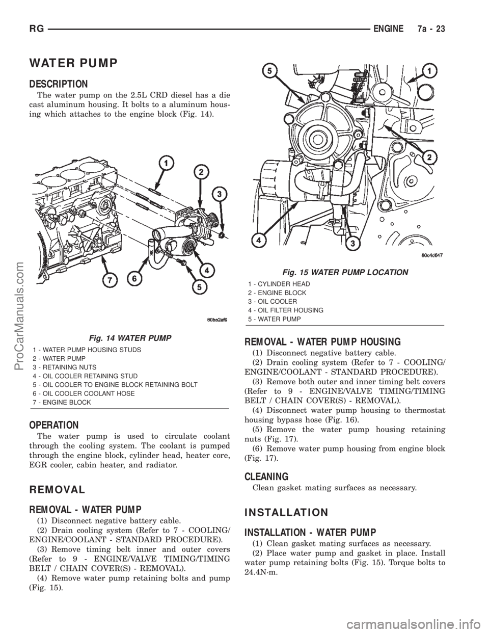
The water pump on the 2.5L CRD diesel has a die
cast aluminum housing. It bolts to a aluminum hous-
ing which attaches to the engine block (Fig. 14).
OPERATION
The water pump is used to circulate coolant
through the cooling system. The coolant is pumped
through the engine block, cylinder head, heater core,
EGR cooler, cabin heater, and radiator.
REMOVAL
REMOVAL - WATER PUMP
(1) Disconnect negative battery cable.
(2) Drain cooling system (Refer to 7 - COOLING/
ENGINE/COOLANT - STANDARD PROCEDURE).
(3) Remove timing belt inner and outer covers
(Refer to 9 - ENGINE/VALVE TIMING/TIMING
BELT / CHAIN COVER(S) - REMOVAL).
(4) Remove water pump retaining bolts and pump
(Fig. 15).
REMOVAL - WATER PUMP HOUSING
(1) Disconnect negative battery cable.
(2) Drain cooling system (Refer to 7 - COOLING/
ENGINE/COOLANT - STANDARD PROCEDURE).
(3) Remove both outer and inner timing belt covers
(Refer to 9 - ENGINE/VALVE TIMING/TIMING
BELT / CHAIN COVER(S) - REMOVAL).
(4) Disconnect water pump housing to thermostat
housing bypass hose (Fig. 16).
(5) Remove the water pump housing retaining
nuts (Fig. 17).
(6) Remove water pump housing from engine block
(Fig. 17).
CLEANING
Clean gasket mating surfaces as necessary.
INSTALLATION
INSTALLATION - WATER PUMP
(1) Clean gasket mating surfaces as necessary.
(2) Place water pump and gasket in place. Install
water pump retaining bolts (Fig. 15). Torque bolts to
24.4N´m.
Fig. 14 WATER PUMP
1 - WATER PUMP HOUSING STUDS
2 - WATER PUMP
3 - RETAINING NUTS
4 - OIL COOLER RETAINING STUD
5 - OIL COOLER TO ENGINE BLOCK RETAINING BOLT
6 - OIL COOLER COOLANT HOSE
7 - ENGINE BLOCK
Fig. 15 WATER PUMP LOCATION
1 - CYLINDER HEAD
2 - ENGINE BLOCK
3 - OIL COOLER
4 - OIL FILTER HOUSING
5 - WATER PUMP
RGENGINE7a-23
ProCarManuals.com
Page 313 of 2399
(3) Install both inner and outer timing belt covers
(Refer to 9 - ENGINE/VALVE TIMING/TIMING
BELT / CHAIN COVER(S) - INSTALLATION).
(4) Refill cooling system (Refer to 7 - COOLING/
ENGINE/COOLANT - STANDARD PROCEDURE).
(5) Connect negative battery cable.
INSTALLATION - WATER PUMP HOUSING
(1) Clean mating serfaces of water pump housing
and engine block as necessary.
(2) Place new o-ring in groove in water pump
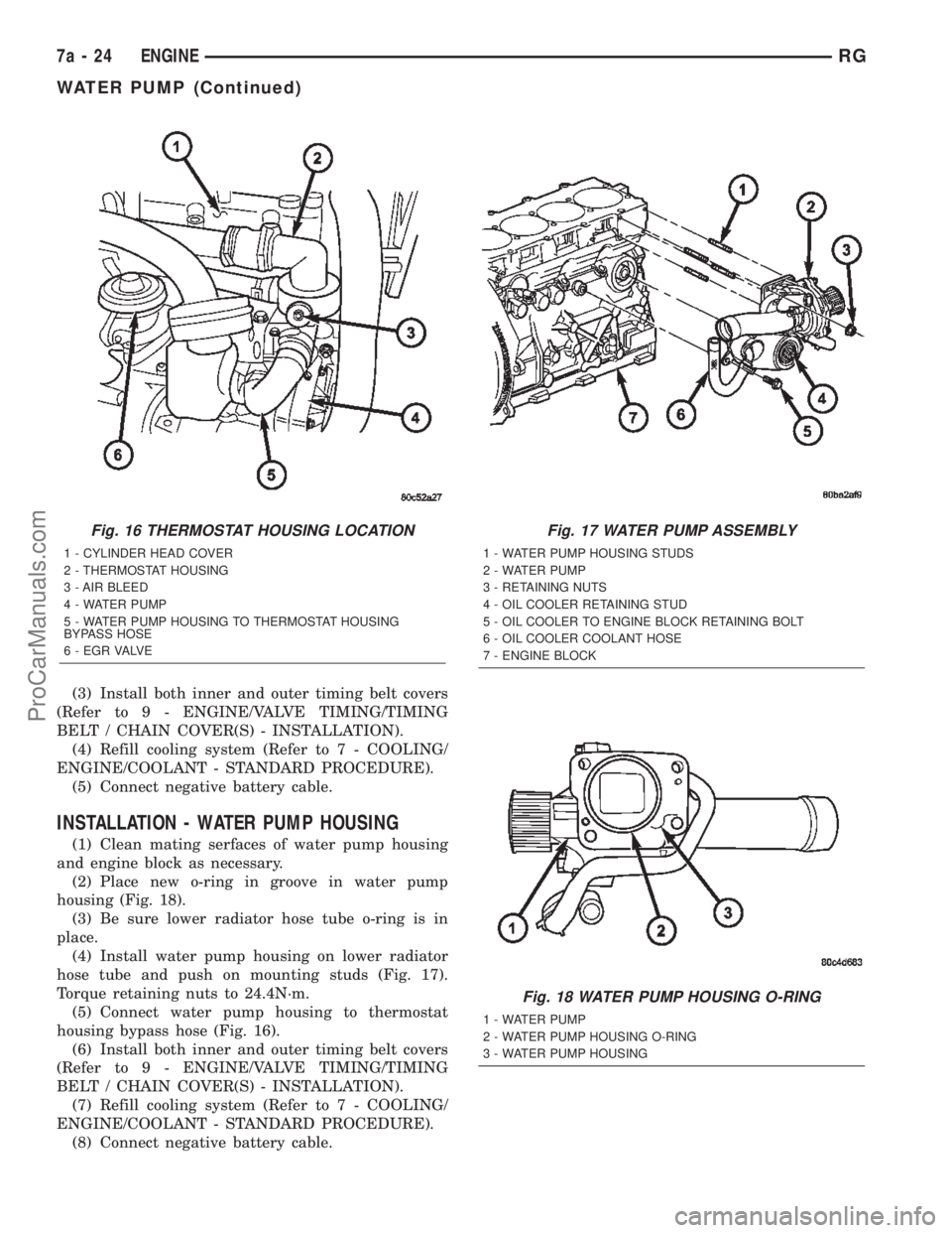
housing (Fig. 18).
(3) Be sure lower radiator hose tube o-ring is in
place.
(4) Install water pump housing on lower radiator
hose tube and push on mounting studs (Fig. 17).
Torque retaining nuts to 24.4N´m.
(5) Connect water pump housing to thermostat
housing bypass hose (Fig. 16).
(6) Install both inner and outer timing belt covers
(Refer to 9 - ENGINE/VALVE TIMING/TIMING
BELT / CHAIN COVER(S) - INSTALLATION).
(7) Refill cooling system (Refer to 7 - COOLING/
ENGINE/COOLANT - STANDARD PROCEDURE).
(8) Connect negative battery cable.
Fig. 16 THERMOSTAT HOUSING LOCATION
1 - CYLINDER HEAD COVER
2 - THERMOSTAT HOUSING
3 - AIR BLEED
4 - WATER PUMP
5 - WATER PUMP HOUSING TO THERMOSTAT HOUSING
BYPASS HOSE
6 - E G R VA LV E
Fig. 17 WATER PUMP ASSEMBLY
1 - WATER PUMP HOUSING STUDS
2 - WATER PUMP
3 - RETAINING NUTS
4 - OIL COOLER RETAINING STUD
5 - OIL COOLER TO ENGINE BLOCK RETAINING BOLT
6 - OIL COOLER COOLANT HOSE
7 - ENGINE BLOCK
Fig. 18 WATER PUMP HOUSING O-RING
1 - WATER PUMP
2 - WATER PUMP HOUSING O-RING
3 - WATER PUMP HOUSING
7a - 24 ENGINERG
WATER PUMP (Continued)
ProCarManuals.com
Page 359 of 2399
(M) Check Engine Lamp (MIL) will illuminate during engine operation if this Diagnostic Trouble Code was recorded.
(G) Generator Lamp Illuminated
GENERIC
SCAN TOOL
CODEDRB SCAN TOOL DISPLAY DESCRIPTION OF DIAGNOSTIC TROUBLE CODE
P1298 Lean Operation at Wide Open Throttle A prolonged lean condition is detected during Wide Open
Throttle.
P1299 (M) Vacuum Leak Found (IAC Fully
Seated)MAP Sensor signal does not correlate to Throttle Position
Sensor signal. Possible vacuum leak.
P1388 Auto Shutdown Relay Control Circuit An open or shorted condition detected in the ASD or CNG
shutoff relay control ckt.
P1389 No ASD Relay Output Voltage At PCM No Z1 or Z2 voltage sensed when the auto shutdown relay is
energized.
P1390 (M) Timing Belt Skipped 1 Tooth or More Relationship between Cam and Crank signals not correct.
P1391 (M) Intermittent Loss of CMP or CKP Loss of the Cam Position Sensor or Crank Position sensor
has occurred. For PL 2.0L
P1398 (M) Mis-Fire Adaptive Numerator at Limit PCM is unable to learn the Crank Sensor's signal in
preparation for Misfire Diagnostics. Probable defective Crank
Sensor.
P1399 Wait To Start Lamp Circuit An open or shorted condition detected in the Wait to Start
Lamp circuit.
P1403 No 5 Volts to EGR Sensor Loss of 5v feed to the EGR position sensor.
P1476 Too Little Secondary Air Insufficient flow of secondary air injection detected during
aspirator test.(was P0411)
P1477 Too Much Secondary Air Excessive flow of secondary air injection detected during
aspirator test (was P0411).
P1478 (M) Battery Temp Sensor Volts Out of Limit Internal temperature sensor input voltage out of an
acceptable range.
P1479 Transmission Fan Relay Circuit An open or shorted condition detected in the transmission
fan relay circuit.
P1480 PCV Solenoid Circuit An open or shorted condition detected in the PCV solenoid
circuit.
P1481 EATX RPM Pulse Performance ETAX RPM pulse generator signal for misfire detection does
not correlate with expected value.
P1482 Catalyst Temperature Sensor Circuit
Shorted LowCatalyst temperature sensor circuit shorted low.
P1483 Catalyst Temperature Sensor Circuit
Shorted High.Catalyst temperature sensor circuit shorted high.
P1484 Catalytic Converter Overheat Detected A catalyst overheat condition has been detected by the
catalyst temperature sensor.
P1485 Air Injection Solenoid Circuit An open or shorted condition detected in the air assist
solenoid circuit.
P1486 (M) Evap Leak Monitor Pinched Hose
FoundLDP has detected a pinched hose in the evaporative hose
system.
P1487 Hi Speed Rad Fan CTRL Relay Circuit An open or shorted condition detected in the control circuit of
the #2 high speed radiator fan control relay.
P1488 Auxiliary 5 Volt Supply Output Too Low Auxiliary 5 volt sensor feed is sensed to be below an
acceptable limit.
8E - 22 ELECTRONIC CONTROL MODULESRS
POWERTRAIN CONTROL MODULE (Continued)
ProCarManuals.com
Page 1204 of 2399
EXHAUST MANIFOLD
DESCRIPTION.........................62
OPERATION...........................62
REMOVAL.............................62
CLEANING............................62
INSPECTION..........................62
INSTALLATION.........................62
TIMING BELT COVER(S)
REMOVAL.............................63
INSTALLATION.........................63
TIMING BELT AND SPROCKET(S)
REMOVAL
REMOVAL - TIMING BELT...............64REMOVAL - CRANKSHAFT SPROCKET....66
CLEANING............................66
INSTALLATION
INSTALLATION - CRANKSHAFT SPROCKET . 66
INSTALLATION - TIMING BELT...........67
TIMING BELT TENSIONER & PULLEY
REMOVAL.............................68
INSTALLATION.........................69
BALANCE SHAFTS AND CARRIER ASSEMBLY
DESCRIPTION.........................69
OPERATION...........................70
REMOVAL.............................70
INSTALLATION.........................71
ENGINE 2.4L
DESCRIPTION
The 2.4 Liter (148 cu. in.) in-line four cylinder
engine is a double over head camshaft with hydraulic
lash adjusters and four valve per cylinder design.
The engine is free-wheeling; meaning it has provi-
sions for piston-to-valve clearance. However valve-to-
valve interference can occur, if camshafts are rotated
independently.
The cylinders are numbered from front of the
engine to the rear. The firing order is 1±3±4±2.
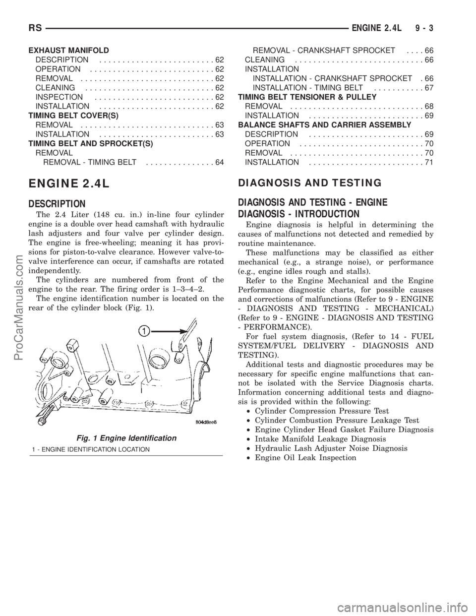
The engine identification number is located on the
rear of the cylinder block (Fig. 1).
DIAGNOSIS AND TESTING
DIAGNOSIS AND TESTING - ENGINE
DIAGNOSIS - INTRODUCTION
Engine diagnosis is helpful in determining the
causes of malfunctions not detected and remedied by
routine maintenance.
These malfunctions may be classified as either
mechanical (e.g., a strange noise), or performance
(e.g., engine idles rough and stalls).
Refer to the Engine Mechanical and the Engine
Performance diagnostic charts, for possible causes
and corrections of malfunctions (Refer to 9 - ENGINE
- DIAGNOSIS AND TESTING - MECHANICAL)
(Refer to 9 - ENGINE - DIAGNOSIS AND TESTING
- PERFORMANCE).
For fuel system diagnosis, (Refer to 14 - FUEL
SYSTEM/FUEL DELIVERY - DIAGNOSIS AND
TESTING).
Additional tests and diagnostic procedures may be
necessary for specific engine malfunctions that can-
not be isolated with the Service Diagnosis charts.
Information concerning additional tests and diagno-
sis is provided within the following:
²Cylinder Compression Pressure Test
²Cylinder Combustion Pressure Leakage Test
²Engine Cylinder Head Gasket Failure Diagnosis
²Intake Manifold Leakage Diagnosis
²Hydraulic Lash Adjuster Noise Diagnosis
²Engine Oil Leak Inspection
Fig. 1 Engine Identification
1 - ENGINE IDENTIFICATION LOCATION
RSENGINE 2.4L9-3
ProCarManuals.com
Page 1205 of 2399
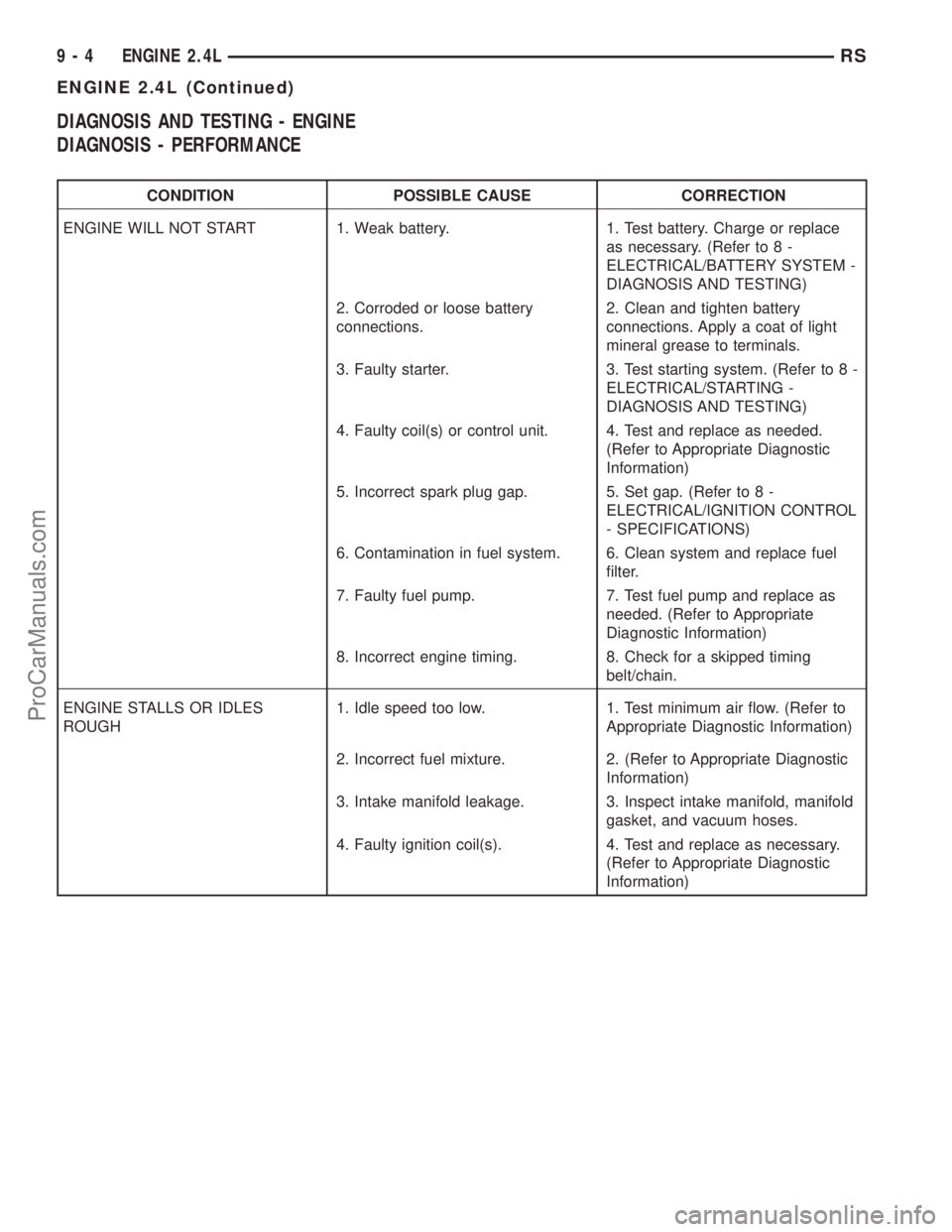
DIAGNOSIS AND TESTING - ENGINE
DIAGNOSIS - PERFORMANCE
CONDITION POSSIBLE CAUSE CORRECTION
ENGINE WILL NOT START 1. Weak battery. 1. Test battery. Charge or replace
as necessary. (Refer to 8 -
ELECTRICAL/BATTERY SYSTEM -
DIAGNOSIS AND TESTING)
2. Corroded or loose battery
connections.2. Clean and tighten battery
connections. Apply a coat of light
mineral grease to terminals.
3. Faulty starter. 3. Test starting system. (Refer to 8 -
ELECTRICAL/STARTING -
DIAGNOSIS AND TESTING)
4. Faulty coil(s) or control unit. 4. Test and replace as needed.
(Refer to Appropriate Diagnostic
Information)
5. Incorrect spark plug gap. 5. Set gap. (Refer to 8 -
ELECTRICAL/IGNITION CONTROL
- SPECIFICATIONS)
6. Contamination in fuel system. 6. Clean system and replace fuel
filter.
7. Faulty fuel pump. 7. Test fuel pump and replace as
needed. (Refer to Appropriate
Diagnostic Information)
8. Incorrect engine timing. 8. Check for a skipped timing
belt/chain.
ENGINE STALLS OR IDLES
ROUGH1. Idle speed too low. 1. Test minimum air flow. (Refer to
Appropriate Diagnostic Information)
2. Incorrect fuel mixture. 2. (Refer to Appropriate Diagnostic
Information)
3. Intake manifold leakage. 3. Inspect intake manifold, manifold
gasket, and vacuum hoses.
4. Faulty ignition coil(s). 4. Test and replace as necessary.
(Refer to Appropriate Diagnostic
Information)
9 - 4 ENGINE 2.4LRS
ENGINE 2.4L (Continued)
ProCarManuals.com