wheel size CHRYSLER VOYAGER 2002 Service Manual
[x] Cancel search | Manufacturer: CHRYSLER, Model Year: 2002, Model line: VOYAGER, Model: CHRYSLER VOYAGER 2002Pages: 2399, PDF Size: 57.96 MB
Page 26 of 2399
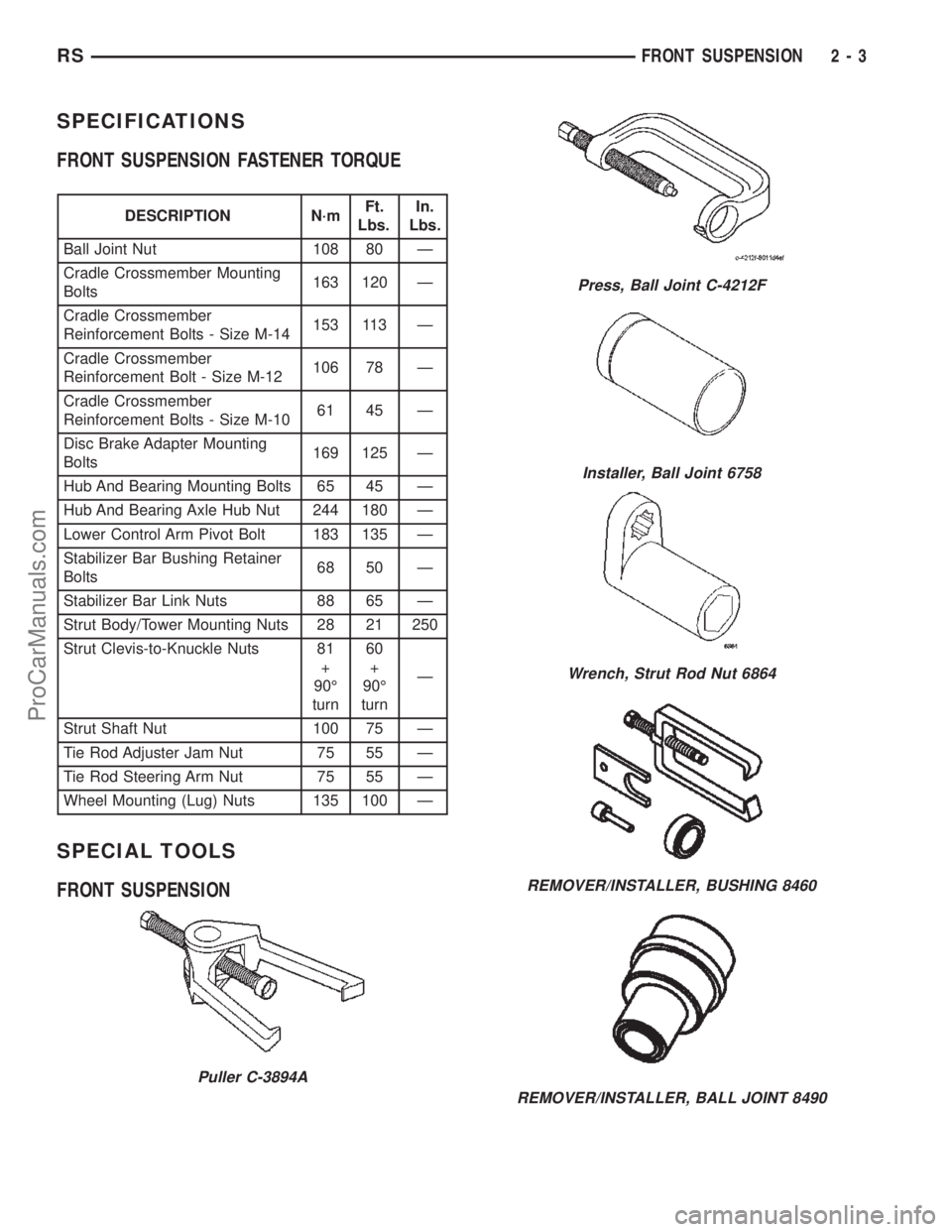
SPECIFICATIONS
FRONT SUSPENSION FASTENER TORQUE
DESCRIPTION N´mFt.
Lbs.In.
Lbs.
Ball Joint Nut 108 80 Ð
Cradle Crossmember Mounting
Bolts163 120 Ð
Cradle Crossmember
Reinforcement Bolts - Size M-14153 113 Ð
Cradle Crossmember
Reinforcement Bolt - Size M-12106 78 Ð
Cradle Crossmember
Reinforcement Bolts - Size M-1061 45 Ð
Disc Brake Adapter Mounting
Bolts169 125 Ð
Hub And Bearing Mounting Bolts 65 45 Ð
Hub And Bearing Axle Hub Nut 244 180 Ð
Lower Control Arm Pivot Bolt 183 135 Ð
Stabilizer Bar Bushing Retainer
Bolts68 50 Ð
Stabilizer Bar Link Nuts 88 65 Ð
Strut Body/Tower Mounting Nuts 28 21 250
Strut Clevis-to-Knuckle Nuts 81
+
90É
turn60
+
90É
turnÐ
Strut Shaft Nut 100 75 Ð
Tie Rod Adjuster Jam Nut 75 55 Ð
Tie Rod Steering Arm Nut 75 55 Ð
Wheel Mounting (Lug) Nuts 135 100 Ð
SPECIAL TOOLS
FRONT SUSPENSION
Puller C-3894A
Press, Ball Joint C-4212F
Installer, Ball Joint 6758
Wrench, Strut Rod Nut 6864
REMOVER/INSTALLER, BUSHING 8460
REMOVER/INSTALLER, BALL JOINT 8490
RSFRONT SUSPENSION2-3
ProCarManuals.com
Page 39 of 2399

(2) Install NEW pivot bolt attaching front bushing
of lower control arm to front suspension cradle cross-
member (Fig. 29).Do not tighten or torque pivot
bolt at this time.
(3) Install the reinforcement on the front suspen-
sion cradle crossmember and install the bolts attach-
ing the reinforcement to the cradle crossmember
(Fig. 22). Tighten the M-14 size bolts to a torque of
153 N´m (113 ft. lbs.). Tighten the M-12 size bolts to
a torque of 106 N´m (78 ft. lbs.).
(4) Install the lower control arm rear bushing
retainer bolts through reinforcement on each side of
each lower control arm rear bushing. Tighten these
M-10 size bolts to a torque of 61 N´m (45 ft. lbs.).
(5) Install the two bolts and bushings attaching
the reinforcement and rear of cradle crossmember to
body of vehicle (Fig. 22). Tighten bolts to a torque of
163 N´m (120 ft. lbs.).
(6) Install the power steering cooler (Fig. 21).
Tighten bolts to a torque of 11 N´m (100 in. lbs.).
(7) Reinstall steering knuckle, brake rotor and cal-
iper. (Refer to 2 - SUSPENSION/FRONT/KNUCKLE
- INSTALLATION)
CAUTION: When locating jack stands under lower
control arms, do not place the jack stands under
the ball joints (Fig. 30).
(8) Position jack stands under the lower control
arms as close to the ball joints as possible (Fig. 30).
Lower the vehicle onto the jack stands until the jack
stands are supporting the total weight of the vehicle.
(9) Tighten front lower control arm pivot bolt to a
torque of 183 N´m (135 ft. lbs.).(10) Install the wheel and tire assembly. Install
and tighten the wheel mounting stud nuts in proper
sequence until all nuts are torqued to half specifica-
tion. Then repeat the tightening sequence to the full
specified torque of 135 N´m (100 ft. lbs.).
(11) Raise vehicle, remove jack stands and lower
vehicle to the ground.
(12) Perform front wheel alignment as necessary.
(Refer to 2 - SUSPENSION/WHEEL ALIGNMENT -
STANDARD PROCEDURE)
STABILIZER BAR
DESCRIPTION
The stabilizer bar interconnects both front struts of
the vehicle and is attached to the front crossmember
(Fig. 1) .
Attachment of the stabilizer bar to the front cross-
member is through 2 rubber-isolator cushion bush-
ings and retainers. A double ball jointed stabilizer
bar link is used to attach each end of the stabilizer
bar to the front strut assemblies. All parts of the sta-
bilizer bar are replaceable as individual components.
The stabilizer bar to front crossmember cushion
bushings are split for easy removal and installation.
The split in the bushings should be positioned toward
the rear of the vehicle, with the square corner facing
down, when the stabilizer bar is installed.
OPERATION
Jounce and rebound movements affecting one
wheel are partially transmitted to the opposite wheel
of the vehicle through the stabilizer bar. This helps
Fig. 29 Lower Control Arm Bushing Pivot Bolt
Correctly Installed
1 - PIVOT BOLT
2 - LOWER CONTROL ARM
3 - FRONT SUSPENSION CRADLE CROSSMEMBER
Fig. 30 Jack Stands Supporting Vehicle Weight
1 - LOWER CONTROL ARMS
2 - BALL JOINT
3 - JACK STANDS
4 - BALL JOINT
2 - 16 FRONT SUSPENSIONRS
LOWER CONTROL ARM (Continued)
ProCarManuals.com
Page 74 of 2399
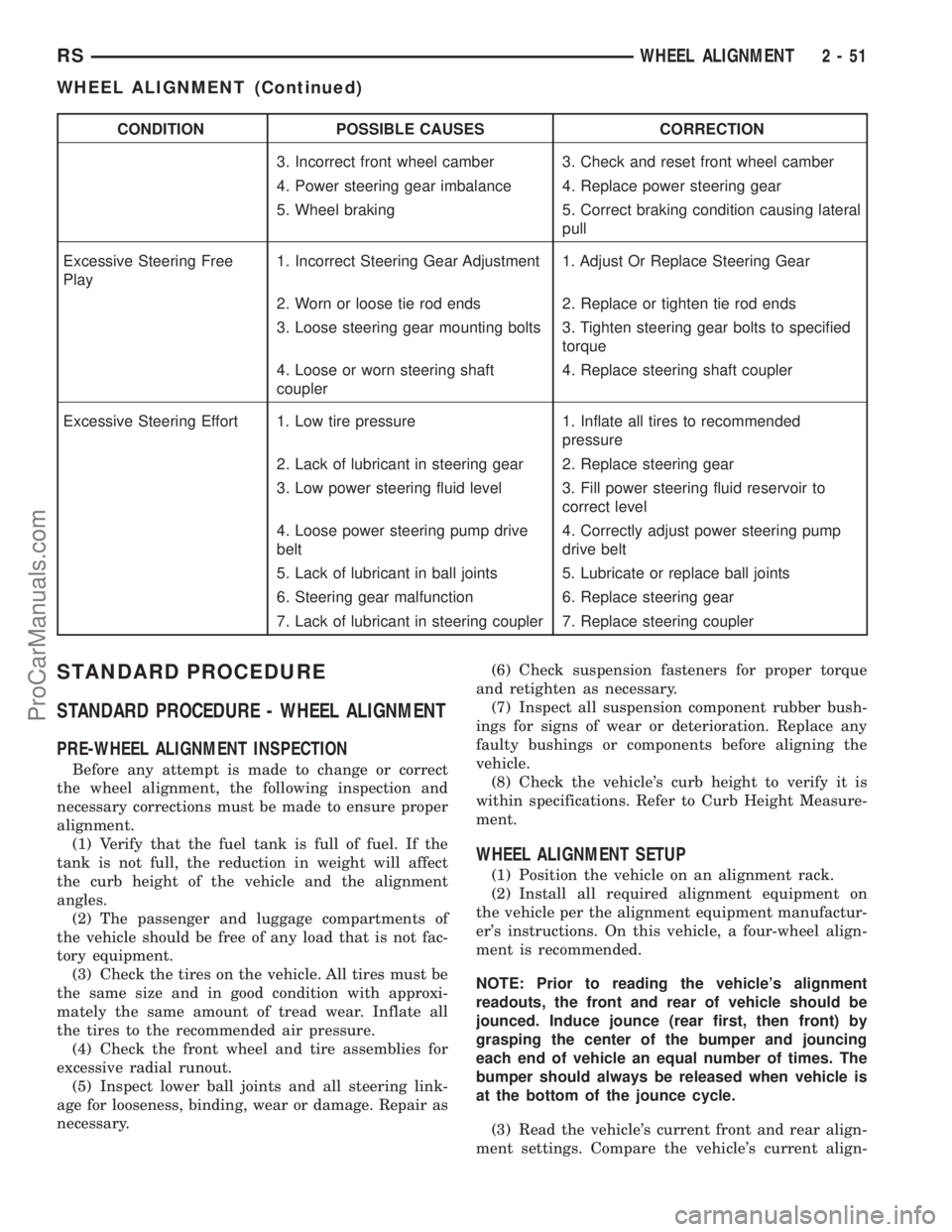
CONDITION POSSIBLE CAUSES CORRECTION
3. Incorrect front wheel camber 3. Check and reset front wheel camber
4. Power steering gear imbalance 4. Replace power steering gear
5. Wheel braking 5. Correct braking condition causing lateral
pull
Excessive Steering Free
Play1. Incorrect Steering Gear Adjustment 1. Adjust Or Replace Steering Gear
2. Worn or loose tie rod ends 2. Replace or tighten tie rod ends
3. Loose steering gear mounting bolts 3. Tighten steering gear bolts to specified
torque
4. Loose or worn steering shaft
coupler4. Replace steering shaft coupler
Excessive Steering Effort 1. Low tire pressure 1. Inflate all tires to recommended
pressure
2. Lack of lubricant in steering gear 2. Replace steering gear
3. Low power steering fluid level 3. Fill power steering fluid reservoir to
correct level
4. Loose power steering pump drive
belt4. Correctly adjust power steering pump
drive belt
5. Lack of lubricant in ball joints 5. Lubricate or replace ball joints
6. Steering gear malfunction 6. Replace steering gear
7. Lack of lubricant in steering coupler 7. Replace steering coupler
STANDARD PROCEDURE
STANDARD PROCEDURE - WHEEL ALIGNMENT
PRE-WHEEL ALIGNMENT INSPECTION
Before any attempt is made to change or correct
the wheel alignment, the following inspection and
necessary corrections must be made to ensure proper
alignment.
(1) Verify that the fuel tank is full of fuel. If the
tank is not full, the reduction in weight will affect
the curb height of the vehicle and the alignment
angles.
(2) The passenger and luggage compartments of
the vehicle should be free of any load that is not fac-
tory equipment.
(3) Check the tires on the vehicle. All tires must be
the same size and in good condition with approxi-
mately the same amount of tread wear. Inflate all
the tires to the recommended air pressure.
(4) Check the front wheel and tire assemblies for
excessive radial runout.
(5) Inspect lower ball joints and all steering link-
age for looseness, binding, wear or damage. Repair as
necessary.(6) Check suspension fasteners for proper torque
and retighten as necessary.
(7) Inspect all suspension component rubber bush-
ings for signs of wear or deterioration. Replace any
faulty bushings or components before aligning the
vehicle.
(8) Check the vehicle's curb height to verify it is
within specifications. Refer to Curb Height Measure-
ment.
WHEEL ALIGNMENT SETUP
(1) Position the vehicle on an alignment rack.
(2) Install all required alignment equipment on
the vehicle per the alignment equipment manufactur-
er's instructions. On this vehicle, a four-wheel align-
ment is recommended.
NOTE: Prior to reading the vehicle's alignment
readouts, the front and rear of vehicle should be
jounced. Induce jounce (rear first, then front) by
grasping the center of the bumper and jouncing
each end of vehicle an equal number of times. The
bumper should always be released when vehicle is
at the bottom of the jounce cycle.
(3) Read the vehicle's current front and rear align-
ment settings. Compare the vehicle's current align-
RSWHEEL ALIGNMENT2-51
WHEEL ALIGNMENT (Continued)
ProCarManuals.com
Page 77 of 2399
CAUTION: Do not twist front inner tie rod to steer-
ing gear rubber boots during front wheel Toe
adjustment.
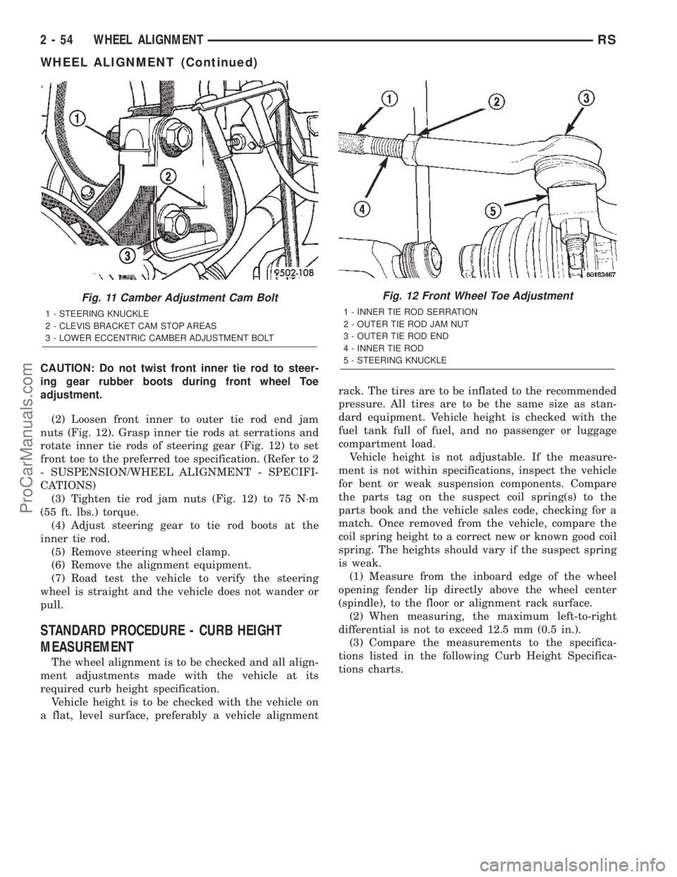
(2) Loosen front inner to outer tie rod end jam
nuts (Fig. 12). Grasp inner tie rods at serrations and
rotate inner tie rods of steering gear (Fig. 12) to set
front toe to the preferred toe specification. (Refer to 2
- SUSPENSION/WHEEL ALIGNMENT - SPECIFI-
CATIONS)
(3) Tighten tie rod jam nuts (Fig. 12) to 75 N´m
(55 ft. lbs.) torque.
(4) Adjust steering gear to tie rod boots at the
inner tie rod.
(5) Remove steering wheel clamp.
(6) Remove the alignment equipment.
(7) Road test the vehicle to verify the steering
wheel is straight and the vehicle does not wander or
pull.
STANDARD PROCEDURE - CURB HEIGHT
MEASUREMENT
The wheel alignment is to be checked and all align-
ment adjustments made with the vehicle at its
required curb height specification.
Vehicle height is to be checked with the vehicle on
a flat, level surface, preferably a vehicle alignmentrack. The tires are to be inflated to the recommended
pressure. All tires are to be the same size as stan-
dard equipment. Vehicle height is checked with the
fuel tank full of fuel, and no passenger or luggage
compartment load.
Vehicle height is not adjustable. If the measure-
ment is not within specifications, inspect the vehicle
for bent or weak suspension components. Compare
the parts tag on the suspect coil spring(s) to the
parts book and the vehicle sales code, checking for a
match. Once removed from the vehicle, compare the
coil spring height to a correct new or known good coil
spring. The heights should vary if the suspect spring
is weak.
(1) Measure from the inboard edge of the wheel
opening fender lip directly above the wheel center
(spindle), to the floor or alignment rack surface.
(2) When measuring, the maximum left-to-right
differential is not to exceed 12.5 mm (0.5 in.).
(3) Compare the measurements to the specifica-
tions listed in the following Curb Height Specifica-
tions charts.
Fig. 11 Camber Adjustment Cam Bolt
1 - STEERING KNUCKLE
2 - CLEVIS BRACKET CAM STOP AREAS
3 - LOWER ECCENTRIC CAMBER ADJUSTMENT BOLT
Fig. 12 Front Wheel Toe Adjustment
1 - INNER TIE ROD SERRATION
2 - OUTER TIE ROD JAM NUT
3 - OUTER TIE ROD END
4 - INNER TIE ROD
5 - STEERING KNUCKLE
2 - 54 WHEEL ALIGNMENTRS
WHEEL ALIGNMENT (Continued)
ProCarManuals.com
Page 78 of 2399
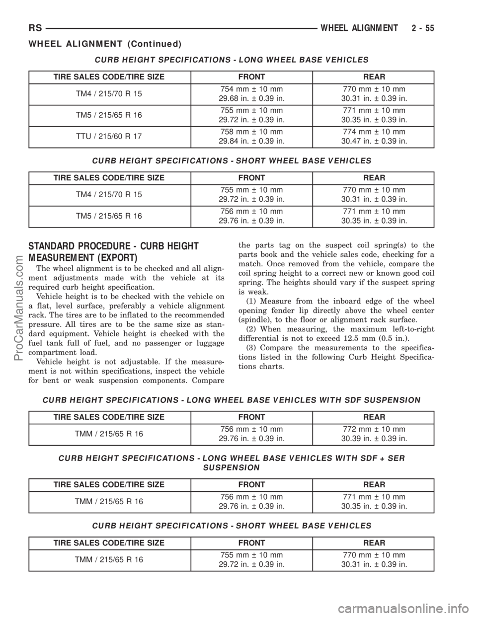
CURB HEIGHT SPECIFICATIONS - LONG WHEEL BASE VEHICLES
TIRE SALES CODE/TIRE SIZE FRONT REAR
TM4 / 215/70 R 15754mm 10mm
29.68 in. 0.39 in.770mm 10mm
30.31 in. 0.39 in.
TM5 / 215/65 R 16755mm 10mm
29.72 in. 0.39 in.771mm 10mm
30.35 in. 0.39 in.
TTU / 215/60 R 17758mm 10mm
29.84 in. 0.39 in.774mm 10mm
30.47 in. 0.39 in.
CURB HEIGHT SPECIFICATIONS - SHORT WHEEL BASE VEHICLES
TIRE SALES CODE/TIRE SIZE FRONT REAR
TM4 / 215/70 R 15755mm 10mm
29.72 in. 0.39 in.770mm 10mm
30.31 in. 0.39 in.
TM5 / 215/65 R 16756mm 10mm
29.76 in. 0.39 in.771mm 10mm
30.35 in. 0.39 in.
STANDARD PROCEDURE - CURB HEIGHT
MEASUREMENT (EXPORT)
The wheel alignment is to be checked and all align-
ment adjustments made with the vehicle at its
required curb height specification.
Vehicle height is to be checked with the vehicle on
a flat, level surface, preferably a vehicle alignment
rack. The tires are to be inflated to the recommended
pressure. All tires are to be the same size as stan-
dard equipment. Vehicle height is checked with the
fuel tank full of fuel, and no passenger or luggage
compartment load.
Vehicle height is not adjustable. If the measure-
ment is not within specifications, inspect the vehicle
for bent or weak suspension components. Comparethe parts tag on the suspect coil spring(s) to the
parts book and the vehicle sales code, checking for a
match. Once removed from the vehicle, compare the
coil spring height to a correct new or known good coil
spring. The heights should vary if the suspect spring
is weak.
(1) Measure from the inboard edge of the wheel
opening fender lip directly above the wheel center
(spindle), to the floor or alignment rack surface.
(2) When measuring, the maximum left-to-right
differential is not to exceed 12.5 mm (0.5 in.).
(3) Compare the measurements to the specifica-
tions listed in the following Curb Height Specifica-
tions charts.
CURB HEIGHT SPECIFICATIONS - LONG WHEEL BASE VEHICLES WITH SDF SUSPENSION
TIRE SALES CODE/TIRE SIZE FRONT REAR
TMM / 215/65 R 16756mm 10mm
29.76 in. 0.39 in.772mm 10mm
30.39 in. 0.39 in.
CURB HEIGHT SPECIFICATIONS - LONG WHEEL BASE VEHICLES WITH SDF + SER
SUSPENSION
TIRE SALES CODE/TIRE SIZE FRONT REAR
TMM / 215/65 R 16756mm 10mm
29.76 in. 0.39 in.771mm 10mm
30.35 in. 0.39 in.
CURB HEIGHT SPECIFICATIONS - SHORT WHEEL BASE VEHICLES
TIRE SALES CODE/TIRE SIZE FRONT REAR
TMM / 215/65 R 16755mm 10mm
29.72 in. 0.39 in.770mm 10mm
30.31 in. 0.39 in.
RSWHEEL ALIGNMENT2-55
WHEEL ALIGNMENT (Continued)
ProCarManuals.com
Page 106 of 2399

DIAGNOSIS AND TESTING - REAR DRIVELINE
MODULE OPERATION
Driveline module operation requires relatively
straight-forward diagnosis. Refer to the following
chart:
DRIVELINE MODULE DIAGNOSIS CHART
CONDITION POSSIBLE CAUSES CORRECTION
Rear wheels not
overrunning1) Bi-directional overrunning clutch
failure1) Replace overrunning clutch
components as required
No AWD in forward or
reverse directions, propeller
shaft turning1) Bi-directional overrunning clutch
failure1) Replace overrunning clutch
components as required
2) Viscous coupling failure 2) Replace viscous coupling
3) Rear differential failure 3) Replace the rear differential
assembly
No AWD in forward or
reverse directions, propeller
shaft not turning1) Power transfer unit failure. 1) Replace power transfer unit
components as necessary
Vibration at all speeds,
continuous torque transfer1) Mis-matched tires, worn tires on
front axle.1) Replace worn or incorrect
(mis-matched) tires with same
make and size
REMOVAL
(1) Raise vehicle on hoist.
(2) Drain fluid from overrunning clutch housing
and/or differential assembly if necessary.
(3) Remove propeller shaft. (Refer to 3 - DIFFER-
ENTIAL & DRIVELINE/PROPELLER SHAFT -
REMOVAL)
(4) Disconnect left and right rear halfshafts from
output flanges (Fig. 2).(5) Remove torque arm mount to body bolts.
(6) Position transmission jack to driveline module
assembly and secure assembly to jack.
(7) Remove two driveline module-to-body bolts
(Fig. 3).
(8) Lower driveline module from vehicle and
remove from jack.
Fig. 2 Half Shaft Mounting Bolts
1 - SHAFT
2 - FLANGE
Fig. 3 Rear Drive Line Module Assembly Mounting
Bolts
1 - DRIVELINE MODULE RETAINING BOLT (2)
2 - RUBBER ISOLATOR
3 - WASHER
RSREAR DRIVELINE MODULE3-27
REAR DRIVELINE MODULE (Continued)
ProCarManuals.com
Page 162 of 2399

(5) Position the dust boot into the counterbore of
the caliper assembly piston bore.
(6) Using a hammer and Installer, Special Tool
C-4689 or C-4842 (depending on piston size), and
Handle, Special Tool C-4171, drive the boot into the
counterbore of the caliper as necessary (Fig. 50).
(7) Reinstall the caliper on the vehicle and bleed
the brakes as necessary. Refer to Installation in this
section.
INSTALLATION - REAR DISC BRAKE CALIPER
(1) Completely retract caliper piston back into pis-
ton bore of the caliper.
(2) If removed, install the brake rotor on the hub,
making sure it is squarely seated on the face of the
hub.
CAUTION: Use care when installing the caliper
assembly onto the adapter, so the caliper guide pin
bushings do not get damaged by the mounting
bosses.
(3) Carefully lower caliper and brake shoes over
rotor and onto the adapter using the reverse proce-
dure for removal (Fig. 46).
CAUTION: When installing guide pin bolts extreme
caution should be taken not to cross-thread the cal-
iper guide pin bolts.
(4) Install the caliper guide pin bolts. Tighten the
guide pin bolts to a torque of 35 N´m (26 ft. lbs.).CAUTION: When connecting the brake hose to the
caliper, install new brake hose to caliper special
washers.
(5) Install the brake hose on the caliper. To do
this, first place one NEW special copper washer on
each side of the hose fitting, then slide the banjo bolt
through the fitting. Next, thread the banjo bolt into
the threaded port on the rear of the brake caliper.
Tighten the banjo bolt to a torque of 47 N´m (35 ft.
lbs.).
(6) Install the wheel and tire assembly.
(7) Tighten the wheel mounting stud nuts in
proper sequence until all nuts are torqued to half
specification. Then repeat the tightening sequence to
the full specified torque of 135 N´m (100 ft. lbs.).
(8) Lower the vehicle.
(9) Remove the brake pedal depressor (holding)
tool.
(10) Bleed the hydraulic brake circuit to the brake
caliper. (Refer to 5 - BRAKES - STANDARD PROCE-
DURE)
(11) Road test the vehicle and make several stops
to wear off any foreign material on the brakes and to
seat the brake shoe linings.
Fig. 49 Installing Piston Into Caliper Bore
1 - BOOT
2 - PISTON
3 - CALIPER
Fig. 50 Installing Dust Boot
1 - HAMMER
2 - SPECIAL TOOL C-4171
3 - SPECIAL TOOL C-4689 or C-4842
4 - CALIPER
RSBRAKES - BASE5-33
DISC BRAKE CALIPER - REAR (Continued)
ProCarManuals.com
Page 167 of 2399
CAUTION: Do not hone the bore of the cylinder as
this will remove the anodized surface from the bore.
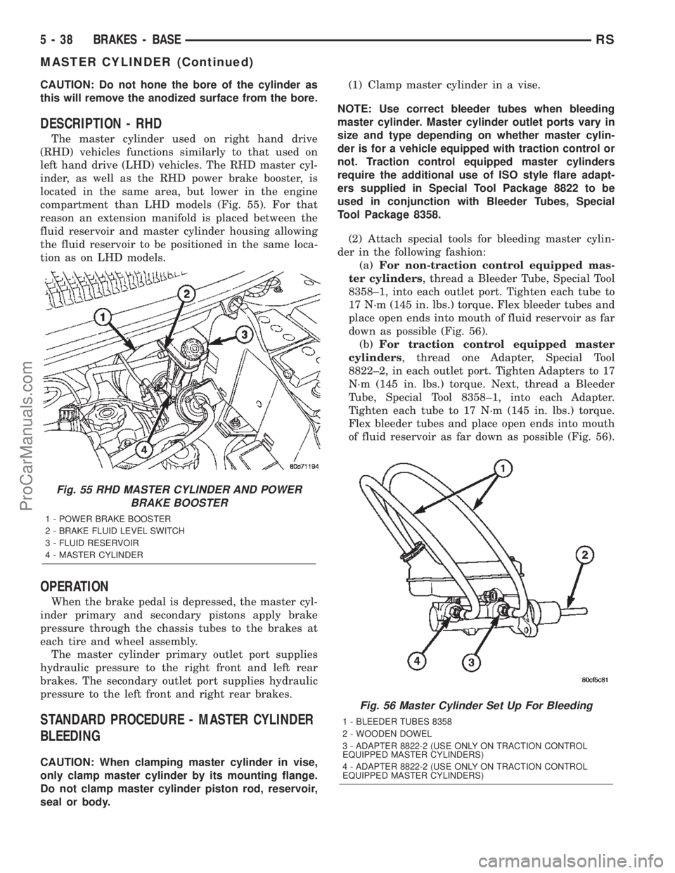
DESCRIPTION - RHD
The master cylinder used on right hand drive
(RHD) vehicles functions similarly to that used on
left hand drive (LHD) vehicles. The RHD master cyl-
inder, as well as the RHD power brake booster, is
located in the same area, but lower in the engine
compartment than LHD models (Fig. 55). For that
reason an extension manifold is placed between the
fluid reservoir and master cylinder housing allowing
the fluid reservoir to be positioned in the same loca-
tion as on LHD models.
OPERATION
When the brake pedal is depressed, the master cyl-
inder primary and secondary pistons apply brake
pressure through the chassis tubes to the brakes at
each tire and wheel assembly.
The master cylinder primary outlet port supplies
hydraulic pressure to the right front and left rear
brakes. The secondary outlet port supplies hydraulic
pressure to the left front and right rear brakes.
STANDARD PROCEDURE - MASTER CYLINDER
BLEEDING
CAUTION: When clamping master cylinder in vise,
only clamp master cylinder by its mounting flange.
Do not clamp master cylinder piston rod, reservoir,
seal or body.(1) Clamp master cylinder in a vise.
NOTE: Use correct bleeder tubes when bleeding
master cylinder. Master cylinder outlet ports vary in
size and type depending on whether master cylin-
der is for a vehicle equipped with traction control or
not. Traction control equipped master cylinders
require the additional use of ISO style flare adapt-
ers supplied in Special Tool Package 8822 to be
used in conjunction with Bleeder Tubes, Special
Tool Package 8358.
(2) Attach special tools for bleeding master cylin-
der in the following fashion:
(a)For non-traction control equipped mas-
ter cylinders, thread a Bleeder Tube, Special Tool
8358±1, into each outlet port. Tighten each tube to
17 N´m (145 in. lbs.) torque. Flex bleeder tubes and
place open ends into mouth of fluid reservoir as far
down as possible (Fig. 56).
(b)For traction control equipped master
cylinders, thread one Adapter, Special Tool
8822±2, in each outlet port. Tighten Adapters to 17
N´m (145 in. lbs.) torque. Next, thread a Bleeder
Tube, Special Tool 8358±1, into each Adapter.
Tighten each tube to 17 N´m (145 in. lbs.) torque.
Flex bleeder tubes and place open ends into mouth
of fluid reservoir as far down as possible (Fig. 56).
Fig. 55 RHD MASTER CYLINDER AND POWER
BRAKE BOOSTER
1 - POWER BRAKE BOOSTER
2 - BRAKE FLUID LEVEL SWITCH
3 - FLUID RESERVOIR
4 - MASTER CYLINDER
Fig. 56 Master Cylinder Set Up For Bleeding
1 - BLEEDER TUBES 8358
2 - WOODEN DOWEL
3 - ADAPTER 8822-2 (USE ONLY ON TRACTION CONTROL
EQUIPPED MASTER CYLINDERS)
4 - ADAPTER 8822-2 (USE ONLY ON TRACTION CONTROL
EQUIPPED MASTER CYLINDERS)
5 - 38 BRAKES - BASERS
MASTER CYLINDER (Continued)
ProCarManuals.com
Page 1508 of 2399
CONDITION POSSIBLE CAUSES CORRECTION
3. Low power steering fluid level. 3. Fill power steering fluid reservoir to
proper level and check for leaks.
4. Loose clamp on fluid supply hose. 4. Tighten or replace hose clamp.
SQUEAK OR RUBBING
SOUND1. Steering column shroud rubbing. 1. Realign shrouds as necessary.
2. Steering column shaft rubbing. 2. Move or realign item rubbing shaft.
3. Clockspring noisy. 3. Remove clockspring. Reinstall wheel.
If noise is gone, replace clockspring.
4. Seal lubrication inadequate. 4. Lube seal (if external).
5. Steering gear internally noisy. 5. Replace steering gear (if no other
cause can be found).
SCRUBBING OR
KNOCKING NOISE.1. Incorrect tire or wheel size. 1. Replace incorrect size tire or wheel
with size used as original equipment.
2. Interference between steering
gear and other vehicle components.2. Check for bent or misaligned
components and correct as necessary.
3. Steering gear internal stops worn
excessively allowing tires to be
steered excessively far.3. Replace steering gear.
NOTE: * There is some noise in all power steering
systems. One of the most common is a hissing
sound evident when turning the steering wheel
when at a standstill or when parking and the steer-
ing wheel is at the end of its travel. Hiss is a very
high frequency noise similar to that experienced
while slowly closing a water tap. The noise is
present in every valve and results when high veloc-
ity fluid passes valve orifice edges. There is no
relationship between this noise and the perfor-
mance of the steering system.
NOTE: ** A light clunk may be felt or heard during
steering wheel reversal while vehicle is stationary.This results from internal steering gear rack move-
ment at the bushings and in no way affects the per-
formance of the steering system. This movement
may be felt in the steering components during
steering wheel reversal.
NOTE: *** Power steering pump growl/moan/groan
results from the development of high pressure fluid
flow. Normally this noise level should not be high
enough to be objectionable.
STEERING WHEEL FEEL
CONDITION POSSIBLE CAUSES CORRECTION
STEERING WHEEL/
COLUMN CLICKING,
CLUNKING OR RATTLING.1. Loose steering coupling pinch
bolt.1. Replace pinch bolt and torque to
specifications.
2. Steering column bearings. 2. Replace steering column.
3. Excessive intermediate shaft
coupling free-play.3. Replace intermediate shaft.
STEERING WHEEL HAS
FORE AND AFT
LOOSENESS.1. Steering wheel retaining nut not
properly tightened and torqued.1. Tighten the steering wheel retaining nut
to its specified torque.
RSSTEERING19-5
STEERING (Continued)
ProCarManuals.com
Page 1531 of 2399

(10) On both sides of vehicle, remove nut attaching
outer tie rod end to steering knuckle (Fig. 4).
Remove nut by holding tie rod end stud with a
socket while loosening and removing nut with
wrench.
(11) Remove bolts fastening leak detection pump to
cradle crossmember reinforcement. (Refer to 25 -EMISSIONS CONTROL/EVAPORATIVE EMIS-
SIONS/LEAK DETECTION PUMP - REMOVAL)
(12) Remove both outer tie rods from steering
knuckles, using Puller, Special Tool C-3894±A (Fig.
5).
(13) Remove the lower control arm rear bushing
retainer bolts located on each side of each lower con-
trol arm rear bushing.
NOTE: The bolts fastening the cradle crossmember
reinforcement are of two different thread sizes. Note
the location of the various sizes.
(14) Remove the bolts attaching the cradle cross-
member reinforcement to the front suspension cradle
crossmember (Fig. 6). Remove the 2 bolts fastening
the reinforcement and rear of cradle crossmember to
the body of the vehicle. Remove lower rear bushings,
then the reinforcement.
(15) If the vehicle is equipped with All-Wheel-
Drive, remove the power transfer unit (Refer to 21 -
TRANSMISSION/TRANSAXLE/POWER TRANSFER
UNIT - REMOVAL).
(16) Remove tube nuts and power steering pres-
sure and return hoses from the power steering gear
(Fig. 7).
Fig. 3 Power Steering Cooler
1 - CRADLE CROSSMEMBER REINFORCEMENT
2 - POWER STEERING COOLER
Fig. 4 Removing/Installing Tie Rod End Attaching
Nut
1 - TIE ROD END
2 - STEERING KNUCKLE
3 - WRENCH
4 - SOCKET
5 - TIE ROD END STUD
Fig. 5 Tie Rod Removal With Tool C-3894-A
1 - OUTER TIE ROD
2 - SPECIAL TOOL C-3894-A
3 - STEERING KNUCKLE
19 - 28 GEARRS
GEAR (Continued)
ProCarManuals.com