torque CHRYSLER VOYAGER 2003 Owners Manual
[x] Cancel search | Manufacturer: CHRYSLER, Model Year: 2003, Model line: VOYAGER, Model: CHRYSLER VOYAGER 2003Pages: 2177, PDF Size: 59.81 MB
Page 241 of 2177
ASSEMBLY - ICU
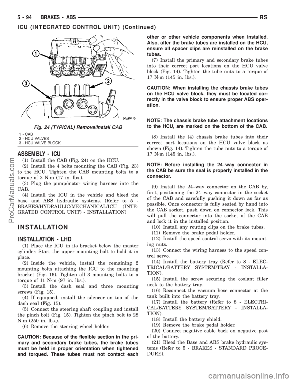
(1) Install the CAB (Fig. 24) on the HCU.
(2) Install the 4 bolts mounting the CAB (Fig. 23)
to the HCU. Tighten the CAB mounting bolts to a
torque of 2 N´m (17 in. lbs.).
(3) Plug the pump/motor wiring harness into the
CAB.
(4) Install the ICU in the vehicle and bleed the
base and ABS hydraulic systems. (Refer to 5 -
BRAKES/HYDRAULIC/MECHANICAL/ICU (INTE-
GRATED CONTROL UNIT) - INSTALLATION)
INSTALLATION
INSTALLATION - LHD
(1) Place the ICU in its bracket below the master
cylinder. Start the upper mounting bolt to hold it in
place.
(2) Inside the vehicle, install the remaining 2
mounting bolts attaching the ICU to the mounting
bracket (Fig. 16). Tighten all 3 mounting bolts to a
torque of 11 N´m (97 in. lbs.).
(3) Install the dash seal and three mounting
screws (Fig. 15).
(4) If equipped, install the silencer on top of the
dash seal (Fig. 15).
(5) Connect the steering shaft coupling and install
the pinch bolt (Fig. 15). Tighten the pinch bolt to 28
N´m (250 in. lbs.).
(6) Remove the steering wheel holder.
CAUTION: Because of the flexible section in the pri-
mary and secondary brake tubes, the brake tubes
must be held in proper orientation when tightened
and torqued. These tubes must not contact eachother or other vehicle components when installed.
Also, after the brake tubes are installed on the HCU,
ensure all spacer clips are reinstalled on the brake
tubes.
(7) Install the primary and secondary brake tubes
into their correct port locations on the HCU valve
block (Fig. 14). Tighten the tube nuts to a torque of
17 N´m (145 in. lbs.).
CAUTION: When installing the chassis brake tubes
on the HCU valve block, they must be located cor-
rectly in the valve block to ensure proper ABS oper-
ation.
NOTE: The chassis brake tube attachment locations
to the HCU, are marked on the bottom of the CAB.
(8) Install the (4) chassis brake tubes into their
correct port locations on the HCU valve block as
shown (Fig. 14). Tighten the tube nuts to a torque of
17 N´m (145 in. lbs.).
NOTE: Before installing the 24±way connector in
the CAB be sure the seal is properly installed in the
connector.
(9) Install the 24±way connector on the CAB by,
first, positioning the 24±way connector in the socket
of the CAB and carefully pushing it down as far as
possible. Once connector is fully seated by hand into
the CAB socket, push down on connector lock. This
will pull the connector into the socket of the CAB
and lock it in the installed position.
(10) Install any routing clips on the brake tubes.
(11) Remove the brake pedal holder.
(12) Install the speed control servo with its mount-
ing nuts.
(13) Connect the wiring harness to the speed con-
trol servo.
(14) Install the battery tray (Refer to 8 - ELEC-
TRICAL/BATTERY SYSTEM/TRAY - INSTALLA-
TION).
(15) Install the screw securing the coolant filler
neck to the battery tray.
(16) Reconnect the vacuum hose connector at the
tank built into the battery tray.
(17) Install the battery (Refer to 8 - ELECTRI-
CAL/BATTERY SYSTEM/BATTERY - INSTALLA-
TION).
(18) Install the battery shield.
(19) Remove the brake pedal holder.
(20) Connect negative cable back on negative post
of the battery.
(21) Bleed the Base and ABS brake hydraulic sys-
tems (Refer to 5 - BRAKES - STANDARD PROCE-
DURE).
Fig. 24 (TYPICAL) Remove/Install CAB
1 - CAB
2 - HCU VALVES
3 - HCU VALVE BLOCK
5 - 94 BRAKES - ABSRS
ICU (INTEGRATED CONTROL UNIT) (Continued)
ProCarManuals.com
Page 242 of 2177
(22) Road test vehicle to ensure proper operation
of the base and antilock brake systems.
INSTALLATION - RHD
(1) Install the ICU on the mounting bracket (Fig.
21). Install the 3 bolts (Fig. 21) attaching the ICU to
the mounting bracket. Tighten the 3 mounting bolts
to a torque of 11 N´m (97 in. lbs.).
CAUTION: The ICU mounting bracket to front sus-
pension cradle mounting bolts have a unique corro-
sion protection coating and a special aluminum
washer. For this reason, only the original, or origi-
nal equipment Mopar replacement bolts can be
used to mount the ICU bracket to the front suspen-
sion crossmember.
(2) Install the ICU and its mounting bracket as an
assembly on the front suspension crossmember.
Install the 3 bolts attaching the ICU bracket to the
crossmember (Fig. 20). Tighten the 3 mounting bolts
to a torque of 28 N´m (250 in. lbs.).
CAUTION: Because of the flexible section in the pri-
mary and secondary brake tubes, and the brake
tubes between the HCU and the proportioning
valve, the brake tubes must be held in proper ori-
entation when tightened and torqued. These tubes
must not contact each other or other vehicle com-
ponents when installed. Also, after the brake tubes
are installed on the HCU, ensure all spacer clips are
reinstalled on the brake tubes.
CAUTION: When installing the chassis brake tubes
on the HCU valve block, they must be located cor-
rectly in the valve block to ensure proper ABS oper-
ation. Refer to (Fig. 19) for the correct chassis
brake tube locations.
NOTE: The chassis brake tube attachment locations
to the HCU, are marked on the bottom of the ICU
mounting bracket.
(3) Install the 6 chassis brake tubes into their cor-
rect port locations on the HCU valve block as shown
in (Fig. 19). Tighten the tube nuts to a torque of 17
N´m (145 in. lbs.).
NOTE: Before installing the 24-way connector in the
CAB be sure the seal is properly installed in the
connector.(4) Install the 24-way connector (Fig. 17) on the
CAB using the following procedure. Position the
24-way connector in the socket of the CAB and care-
fully push it down as far as possible. When connector
is fully seated by hand into the CAB socket, push in
the connector lock (Fig. 18). This will pull the connec-
tor into the socket of the CAB and lock it in the
installed position.
NOTE: The CAB wiring harness must be clipped to
the ICU mounting bracket. This will ensure the wir-
ing harness is properly routed and does not contact
the brake tubes or the body of the vehicle.
(5) Clip the cab wiring harness (Fig. 17) to the
ICU mounting bracket.
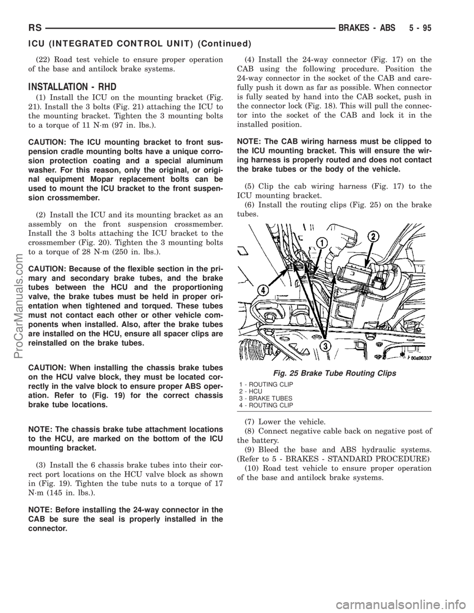
(6) Install the routing clips (Fig. 25) on the brake
tubes.
(7) Lower the vehicle.
(8) Connect negative cable back on negative post of
the battery.
(9) Bleed the base and ABS hydraulic systems.
(Refer to 5 - BRAKES - STANDARD PROCEDURE)
(10) Road test vehicle to ensure proper operation
of the base and antilock brake systems.
Fig. 25 Brake Tube Routing Clips
1 - ROUTING CLIP
2 - HCU
3 - BRAKE TUBES
4 - ROUTING CLIP
RSBRAKES - ABS5-95
ICU (INTEGRATED CONTROL UNIT) (Continued)
ProCarManuals.com
Page 249 of 2177

DIAGNOSIS AND TESTING - DRIVE PLATE
MISALIGNMENT
Common causes of misalignment are:
²Heat warping
²Mounting drive plate on a dirty crankshaft
flange
²Incorrect bolt tightening
²Improper seating on the crankshaft shoulder
²Loose crankshaft bolts
Clean the crankshaft flange before mounting the
drive plate. Dirt and grease on the flange surface
may misalign the flywheel, causing excessive runout.
Use new bolts when mounting drive plate to crank-
shaft. Tighten drive plate bolts to specified torque
only. Over-tightening can distort the drive plate hub
causing excessive runout.
DIAGNOSIS AND TESTING - CLUTCH COVER
AND DISC RUNOUT
Check condition of the clutch cover before installa-
tion. A warped cover or diaphragm spring will cause
grab and/or incomplete release or engagement. Use
care when handling the clutch assembly. Impact can
distort the cover, diaphragm spring, and release fin-
gers.
DIAGNOSIS AND TESTING - CLUTCH CHATTER
COMPLAINTS
For all clutch chatter complaints, perform the fol-
lowing:
(1) Check for loose, misaligned, or broken engine
and transmission mounts. If present, they should be
corrected at this time. Test vehicle for chatter. If
chatter is gone, there is no need to go any further.
(2) If chatter persists, check hydraulic clutch
release system is functioning properly.
(3) Check for loose connections in drivetrain. Cor-
rect any problems and determine if clutch chatter
complaints have been satisfied. If not:
(a) Remove transaxle.
(b) Check to see if the release bearing is sticky
or binding. Replace bearing, if needed.
(c) Check linkage for excessive wear on the pivot
stud and fork fingers. Replace all worn parts.
(d) Check clutch assembly for contamination
(dirt, oil). Replace clutch assembly, if required.
(e) Check to see if the clutch disc hub splines
are damaged. Replace with new clutch assembly, if
necessary.
(f) Check input shaft splines for damage.
Replace, if necessary.
(g) Check for uneven wear on clutch fingers.
(h) Check for broken clutch cover diaphragm
spring fingers. Replace with new clutch assembly,
if necessary.
SPECIAL TOOLS - T850 TRANSAXLE
CLUTCH RELEASE LEVER AND
BEARING
REMOVAL
(1) Remove transaxle assembly. (Refer to 21 -
TRANSMISSION/TRANSAXLE/MANUAL -
REMOVAL)
(2) Remove modular clutch assembly from input
shaft (2.4L Gas models only).
(3) Grasp clutch release lever and bearing (Fig. 6)
with both hands and pull outward using moderate
pressure to release lever from pivot ball.
(4) Separate release bearing from lever.
NOTE: Remove release lever pivot ball(s) ONLY if
replacement is necessary.
Disconnect Tool, 6638A
Remover/Installer, 6891
6 - 6 CLUTCHRS
CLUTCH (Continued)
ProCarManuals.com
Page 255 of 2177
INSTALLATION
(1) Install clutch release bearing and lever (if
removed). (Refer to 6 - CLUTCH/CLUTCH RELEASE
BEARING - INSTALLATION)
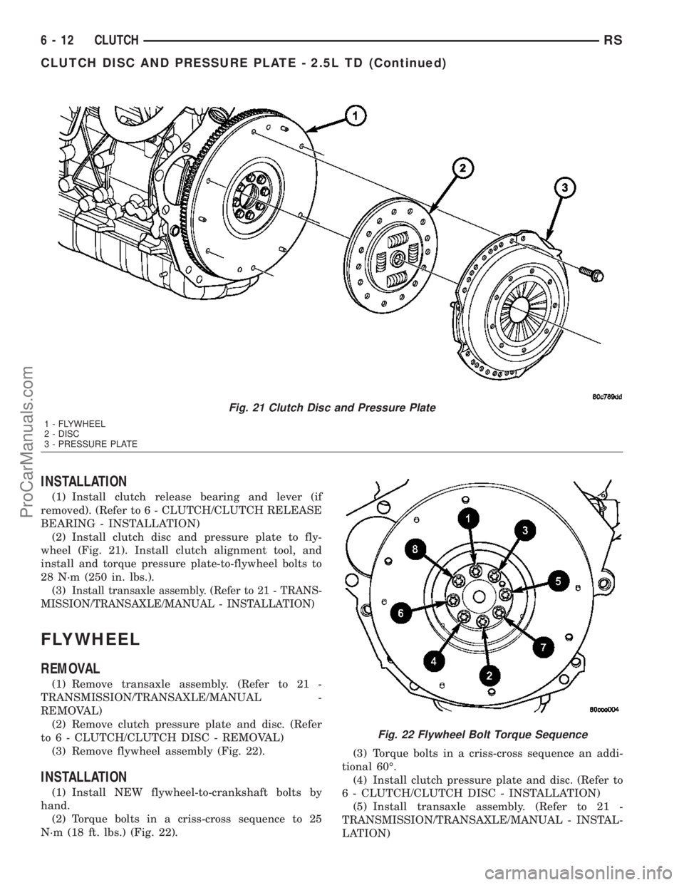
(2) Install clutch disc and pressure plate to fly-
wheel (Fig. 21). Install clutch alignment tool, and
install and torque pressure plate-to-flywheel bolts to
28 N´m (250 in. lbs.).
(3)
Install transaxle assembly. (Refer to 21 - TRANS-
MISSION/TRANSAXLE/MANUAL - INSTALLATION)
FLYWHEEL
REMOVAL
(1) Remove transaxle assembly. (Refer to 21 -
TRANSMISSION/TRANSAXLE/MANUAL -
REMOVAL)
(2) Remove clutch pressure plate and disc. (Refer
to 6 - CLUTCH/CLUTCH DISC - REMOVAL)
(3) Remove flywheel assembly (Fig. 22).
INSTALLATION
(1) Install NEW flywheel-to-crankshaft bolts by
hand.
(2) Torque bolts in a criss-cross sequence to 25
N´m (18 ft. lbs.) (Fig. 22).(3) Torque bolts in a criss-cross sequence an addi-
tional 60É.
(4) Install clutch pressure plate and disc. (Refer to
6 - CLUTCH/CLUTCH DISC - INSTALLATION)
(5) Install transaxle assembly. (Refer to 21 -
TRANSMISSION/TRANSAXLE/MANUAL - INSTAL-
LATION)
Fig. 21 Clutch Disc and Pressure Plate
1 - FLYWHEEL
2 - DISC
3 - PRESSURE PLATE
Fig. 22 Flywheel Bolt Torque Sequence
6 - 12 CLUTCHRS
CLUTCH DISC AND PRESSURE PLATE - 2.5L TD (Continued)
ProCarManuals.com
Page 257 of 2177

INSTALLATION
LHD
(1) Install interlock switch into pedal bracket hole,
and secure harness with retainer as shown in (Fig.
28). Make sure switch wing tabs are fully expanded.
(2) Connect interlock switch connector.
(3) Install knee bolster (Fig. 24).
(4) Install instrument panel lower silencer (Fig.
23).
(5) Connect battery negative cable.
(6) Verify function of starter interlock switch.
Switch must actuate when pedal is depressed.
RHD
(1) Install interlock switch to pedal bracket assem-
bly as shown in (Fig. 28). Secure connector with
retainer to hole in bracket.
(2) Install clutch pedal bracket assembly into posi-
tion. Install pedal bracket mounting nuts and torque
to 28 N´m (250 in. lbs.).
(3) Connect interlock and upstop switch connec-
tors.
(4) Install clutch master cylinder into position and
rotate 45É counter-clockwise to secure to pedal
bracket (Fig. 26). Secure dash panel grommet and
secure hydraulic pluming into dash panel retainers.
(5) Connect master cylinder pushrod to clutch
pedal pin and secure with retainer clip (Fig. 26).
(6) Install knee bolster (Fig. 24).
Fig. 26 Clutch Master Cylinder at Pedal Bracket
1 - CLUTCH MASTER CYLINDER
2 - RETAINER CLIP
3 - CLUTCH PEDAL PIN
4 - PUSH ROD
Fig. 27 Clutch Pedal/Bracket Assembly
1 - CLUTCH PEDAL/BRACKET ASSY.
2 - NUT (4)
Fig. 28 Clutch Pedal Interlock Switch
1 - CLUTCH INTERLOCK SWITCH
2 - CLUTCH PEDAL/BRACKET ASSY.
6 - 14 CLUTCHRS
CLUTCH PEDAL INTERLOCK SWITCH (Continued)
ProCarManuals.com
Page 259 of 2177
RHD
(1) Disconnect battery negative cable.
(2) Remove instrument panel lower silencer (Fig.
29).
(3) Remove knee bolster (Fig. 30).
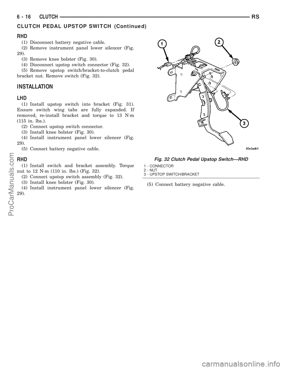
(4) Disconnect upstop switch connector (Fig. 32).
(5) Remove upstop switch/bracket-to-clutch pedal
bracket nut. Remove switch (Fig. 32).
INSTALLATION
LHD
(1) Install upstop switch into bracket (Fig. 31).
Ensure switch wing tabs are fully expanded. If
removed, re-install bracket and torque to 13 N´m
(115 in. lbs.).
(2) Connect upstop switch connector.
(3) Install knee bolster (Fig. 30).
(4) Install instrument panel lower silencer (Fig.
29).
(5) Connect battery negative cable.
RHD
(1) Install switch and bracket assembly. Torque
nut to 12 N´m (110 in. lbs.) (Fig. 32).
(2) Connect upstop switch assembly (Fig. 32).
(3) Install knee bolster (Fig. 30).
(4) Install instrument panel lower silencer (Fig.
29).(5) Connect battery negative cable.
Fig. 32 Clutch Pedal Upstop SwitchÐRHD
1 - CONNECTOR
2 - NUT
3 - UPSTOP SWITCH/BRACKET
6 - 16 CLUTCHRS
CLUTCH PEDAL UPSTOP SWITCH (Continued)
ProCarManuals.com
Page 260 of 2177
COOLING
TABLE OF CONTENTS
page page
COOLING
DESCRIPTION
DESCRIPTION - COOLING SYSTEM........1
DESCRIPTION - HOSE CLAMPS...........1
OPERATION
OPERATION - COOLING SYSTEM.........2
OPERATION - HOSE CLAMPS............2
DIAGNOSIS AND TESTING
DIAGNOSIS AND TESTING - COOLING
SYSTEM LEAK TEST....................2
DIAGNOSIS AND TESTING - COOLING
SYSTEM FLOW CHECK.................3
DIAGNOSIS AND TESTING - COOLING
SYSTEM AERATION....................3
DIAGNOSIS AND TESTING - COOLING
SYSTEM DEAERATION..................4
STANDARD PROCEDURE
STANDARD PROCEDURE - COOLING
SYSTEM DRAINING....................4STANDARD PROCEDURE - COOLING
SYSTEM FILLING......................5
STANDARD PROCEDURE - ADDING
ADDITIONAL COOLANT.................5
STANDARD PROCEDURE - COOLANT
LEVEL CHECK........................5
SPECIFICATIONS
ACCESSORY DRIVE BELT TENSION.......5
TORQUE.............................5
SPECIAL TOOLS
COOLING SYSTEM.....................6
ACCESSORY DRIVE.......................7
ENGINE...............................13
TRANSMISSION.........................37
COOLING
DESCRIPTION
DESCRIPTION - COOLING SYSTEM
The cooling system components consist of a radia-
tor, electric fan motors, shroud, pressure cap, thermo-
stat, transmission oil cooler, water pump, hoses,
clamps, coolant, and a coolant reserve system to com-
plete the circuit.
DESCRIPTION - HOSE CLAMPS
The cooling system uses spring type hose clamps.
If a spring type clamp replacement is necessary,
replace with the original Mopartequipment spring
type clamp.
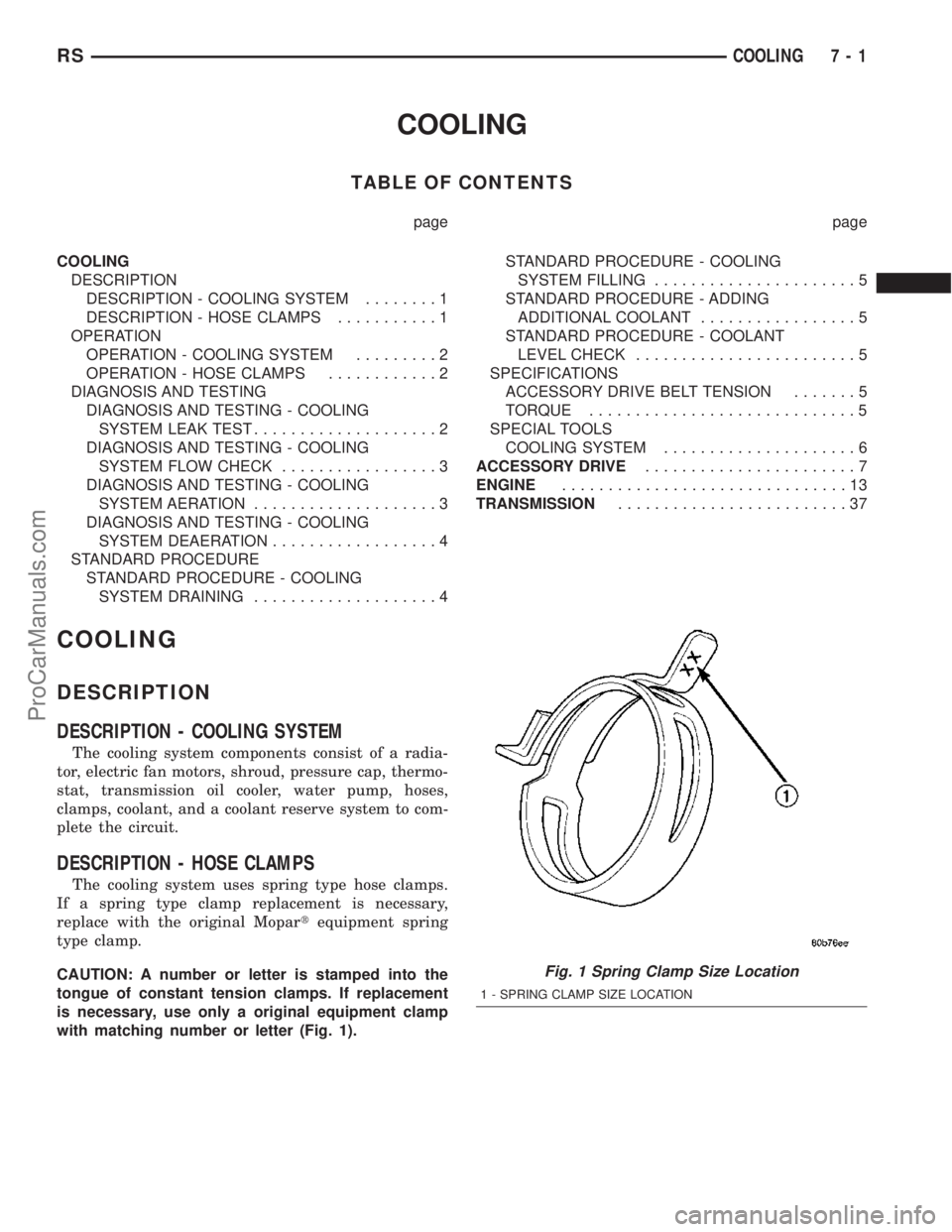
CAUTION: A number or letter is stamped into the
tongue of constant tension clamps. If replacement
is necessary, use only a original equipment clamp
with matching number or letter (Fig. 1).
Fig. 1 Spring Clamp Size Location
1 - SPRING CLAMP SIZE LOCATION
RSCOOLING7-1
ProCarManuals.com
Page 264 of 2177
STANDARD PROCEDURE - COOLING SYSTEM
FILLING
Remove radiator pressure cap (Fig. 6) and fill sys-
tem, using a 50/50 mix of MopartAntifreeze/Coolant,
5 Year/100,000 Mile Formula and distilled water.
Continue filling system until full.Be careful not
to spill coolant on drive belts or the generator.
For cooling system capacity, (Refer to LUBRICATION
& MAINTENANCE/FLUID CAPACITIES - SPECIFI-
CATIONS).
Fill coolant recovery/reserve container (Fig. 6) to at
least the MAX mark with 50/50 solution. It may be
necessary to add coolant to the recovery/reserve con-
tainer after three or four warm up/cool down cycles
to maintain coolant level between the MAX and MIN
mark. This will allow trapped air to be removed from
the system.
STANDARD PROCEDURE - ADDING
ADDITIONAL COOLANT
The radiator cap should not be removed.
When additional coolant is needed to maintain this
level, it should be added to the coolant recovery/re-
serve container (Fig. 6). Use only 50/50 mix of ethyl-
ene glycol type antifreeze and distilled water. For the
recommeded antifreeze/coolant type (Refer to LUBRI-
CATION & MAINTENANCE/FLUID TYPES -
DESCRIPTION).
CAUTION: Do not use well water, or suspect water
supply in cooling system. A 50/50 ethylene glycol
and distilled water mix is recommended. For the
recommeded antifreeze/coolant type (Refer to
LUBRICATION & MAINTENANCE/FLUID TYPES -
DESCRIPTION).
STANDARD PROCEDURE - COOLANT LEVEL
CHECK
NOTE: Do not remove radiator cap for routine cool-
ant level inspections.
The coolant reserve system provides a quick visual
method for determining the coolant level without
removing the radiator cap.With the engine cold
and not running,simply observe the level of the
coolant in the recovery/reserve container (Fig. 6). The
coolant level should be between the MIN and MAX
marks.
SPECIFICATIONS
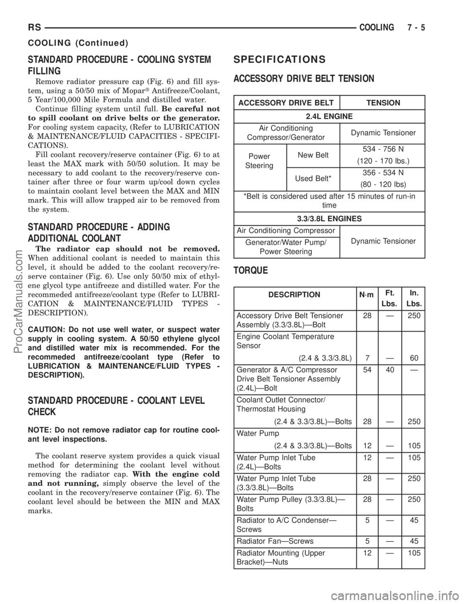
ACCESSORY DRIVE BELT TENSION
ACCESSORY DRIVE BELT TENSION
2.4L ENGINE
Air Conditioning
Compressor/GeneratorDynamic Tensioner
Power
SteeringNew Belt534 - 756 N
(120 - 170 lbs.)
Used Belt*356 - 534 N
(80 - 120 lbs)
*Belt is considered used after 15 minutes of run-in
time
3.3/3.8L ENGINES
Air Conditioning Compressor
Dynamic Tensioner
Generator/Water Pump/
Power Steering
TORQUE
DESCRIPTION N´mFt.
Lbs.In.
Lbs.
Accessory Drive Belt Tensioner
Assembly (3.3/3.8L)ÐBolt28 Ð 250
Engine Coolant Temperature
Sensor
(2.4 & 3.3/3.8L) 7 Ð 60
Generator & A/C Compressor
Drive Belt Tensioner Assembly
(2.4L)ÐBolt54 40 Ð
Coolant Outlet Connector/
Thermostat Housing
(2.4 & 3.3/3.8L)ÐBolts 28 Ð 250
Water Pump
(2.4 & 3.3/3.8L)ÐBolts 12 Ð 105
Water Pump Inlet Tube
(2.4L)ÐBolts12 Ð 105
Water Pump Inlet Tube
(3.3/3.8L)ÐBolts28 Ð 250
Water Pump Pulley (3.3/3.8L)Ð
Bolts28 Ð 250
Radiator to A/C CondenserÐ
Screws5Ð45
Radiator FanÐScrews 5 Ð 45
Radiator Mounting (Upper
Bracket)ÐNuts12 Ð 105
RSCOOLING7-5
COOLING (Continued)
ProCarManuals.com
Page 269 of 2177

INSTALLATION
GENERATOR AND AIR CONDITIONING BELT
(1) Install belt onto all pulleys except for the
crankshaft (Fig. 5).
(2) Rotate belt tensioner clockwise until belt can
be installed onto the crankshaft pulley (Fig. 2).
Slowly release belt tensioner.
(3) Verify belt is properly routed and engaged on
all pulleys (Fig. 5).
(4) Install drive belt shield (Fig. 7) and lower vehi-
cle.
POWER STEERING PUMP
(1) Install belt over crankshaft and power steering
pump pulleys (Fig. 5).
(2) Apply an initial snug torque to pivot bolt (3)
and front locking nut (2) (Fig. 3).
(3) Tighten adjusting bolt (4) until proper belt ten-
sion is obtained (Fig. 3). For belt tension check pro-
cedure, (Refer to 7 - COOLING/ACCESSORY DRIVE/
DRIVE BELTS - STANDARD PROCEDURE -
CHECKING POWER STEERING BELT TENSION).
(4) Tighten pivot bolt (3) and front locking nut (2)
to 54 N´m (40 ft. lbs.) (Fig. 3).
(5) Tighten rear locking nut (1) to 54 N´m (40 ft.
lbs.) (Fig. 3).
ADJUSTMENTS
Satisfactory performance of the belt driven accesso-
ries depends on proper belt tension. Belt tensioning
should be performed with the aid of Special Tool
7198. Because of space limitations in the engine com-
partment, the use of this gauge may be restricted.
Raise the vehicle on a hoist and the remove the
splash shield to gain access to the drive belts, if nec-
essary. Adjust belt tension for either aNeworUsed
belt. For specifications, (Refer to 7 - COOLING/AC-
CESSORY DRIVE - SPECIFICATIONS).
BELT TENSIONER - 2.4L
REMOVAL
(1) Raise vehicle on hoist.
(2) Remove the drive belt shield.
(3) Remove the generator/A/C drive belt. (Refer to
7 - COOLING/ACCESSORY DRIVE/DRIVE BELTS -
REMOVAL)
(4) Remove the belt tensioner (Fig. 6).
INSTALLATION
(1) Install belt tensioner and bolt (Fig. 6). Tighten
bolt to 54 N´m (40 ft. lbs.).
(2) Install generator/A/C compressor drive belt.
(Refer to 7 - COOLING/ACCESSORY DRIVE/DRIVE
BELTS - INSTALLATION)
(3) Install splash shield.
(4) Lower the vehicle.
Fig. 5 Accessory Drive Belts - 2.4L
1 - POWER STEERING PUMP PULLEY
2 - BELT TENSIONER
3 - GENERATOR PULLEY
4 - BELT - A/C AND GENERATOR
5 - A/C COMPRESSOR PULLEY
6 - CRANKSHAFT PULLEY
7 - BELT - POWER STEERING
Fig. 6 Belt Tensioner - 2.4L
1 - BELT TENSIONER
2 - GENERATOR BRACKET
3 - BOLT
7 - 10 ACCESSORY DRIVERS
DRIVE BELTS - 2.4L (Continued)
ProCarManuals.com
Page 291 of 2177

(9) Remove timing belt idler pulley.
(10) Hold camshaft sprocket with Special tool
C-4687 and adaptor C-4687-1 while removing bolt.
Remove both cam sprockets.
(11) Remove the timing belt rear cover (Refer to 9
- ENGINE/VALVE TIMING/TIMING BELT COV-
ER(S) - REMOVAL).
(12) Remove the generator and bracket (Fig. 24).
(13) Remove water pump to engine attaching
screws (Fig. 25).
CLEANING
Clean gasket mating surfaces as necessary.
INSPECTION
Replace water pump body assembly if it has any of
these defects:
(1) Cracks or damage on the body.
(2) Coolant leaks from the shaft seal, evident by
wet coolant traces on the pump body.
(3) Loose or rough turning bearing.
(4) Impeller rubs either the pump body or the
engine block.
(5) Impeller loose or damaged.
(6) Sprocket or sprocket flange loose or damaged.
INSTALLATION
(1) Install new O-ring gasket in water pump body
O-ring locating groove (Fig. 26).
CAUTION: Make sure O-ring is properly seated in
water pump groove before tightening screws. An
improperly located O-ring may be damaged and
cause a coolant leak.
(2) Assemble pump body to block and tighten
screws to 12 N´m (105 in. lbs.) (Fig. 25). Pressurize
cooling system to 103.4 Kpa (15 psi) with pressure
tester and check water pump shaft seal and O-ring
for leaks.
(3) Rotate pump by hand to check for freedom of
movement.
(4) Install the timing belt rear cover (Refer to 9 -
ENGINE/VALVE TIMING/TIMING BELT COVER(S)
- INSTALLATION).
(5) Install camshaft sprockets and torque bolts to
101 N´m (75 ft. lbs.) while holding camshaft sprocket
with Special tool C-4687 and adaptor C-4687-1.
(6) Install timing belt idler pulley and torque
mounting bolt to 61 N´m (45 ft. lbs.).
Fig. 24 Generator Bracket
1 - BRACKET - ENGINE MOUNT 5 - BOLT
2 - BOLT 6 - TENSIONER - DRIVE BELT
3 - GENERATOR 7 - BOLT
4 - BOLT 8 - BOLT
7 - 32 ENGINERS
WATER PUMP - 2.4L (Continued)
ProCarManuals.com