height CHRYSLER VOYAGER 2003 User Guide
[x] Cancel search | Manufacturer: CHRYSLER, Model Year: 2003, Model line: VOYAGER, Model: CHRYSLER VOYAGER 2003Pages: 2177, PDF Size: 59.81 MB
Page 196 of 2177

Here is how the height sensing proportioning valve
differs from a standard proportioning valve. As the
height of the rear suspension changes, the height
sensing portion of the proportioning valve changes
the split point of the proportioning valve. When the
height of the rear suspension is low, the proportion-
ing valve interprets this as extra load and the split
point of the proportioning valve is raised to a higher
pressure to allow for more rear braking. When the
height of the rear suspension is high, the proportion-
ing valve interprets this as a light load and the split
point of the proportioning valve is lowered to a lower
pressure and rear braking is reduced.
The height sensing proportioning valve regulates
the pressure by sensing the load condition of the
vehicle through the movement of the proportioning
valve actuator lever (Fig. 72). As the position of the
rear axle changes, depending on the load the vehicle
is carrying, the movement is transferred to the pro-
portioning valve. The proportioning valve adjusts the
hydraulic pressure accordingly.
The height sensing proportioning valve allows the
brake system to maintain the optimal front to rear
brake balance regardless of the vehicle load condi-
tion. Under a light load condition, hydraulic pressure
to the rear brakes is minimized. As the rear load con-
dition increases, so does the hydraulic pressure to
the rear brakes.
DIAGNOSIS AND TESTING - PROPORTIONING
VALVE (HEIGHT SENSING)
CAUTION: The use of aftermarket load leveling or
load capacity increasing devices on this vehicle is
prohibited. Using air shock absorbers or helpersprings on this vehicle will cause the height sens-
ing proportioning valve to inappropriately reduce
the hydraulic pressure to the rear brakes. This inap-
propriate reduction in hydraulic pressure potentially
could result in increased stopping distance of the
vehicle.
When a premature rear wheel skid is obtained on a
brake application, it may be an indication that the
hydraulic pressure to the rear brakes is above the
specified output from the proportioning valve. This
condition indicates a possible malfunction of the
height sensing proportioning valve, which will
require testing to verify that it is properly controlling
the hydraulic pressure allowed to the rear brakes.
Premature rear wheel skid may also be caused by
contaminated front or rear brake linings.
Prior to testing a proportioning valve for function,
check that all tire pressures are correct. Also, ensure
the front and rear brake linings are in satisfactory
condition.It is also necessary to verify that the
brakes shoe assemblies on a vehicle being
tested are either original equipment manufac-
turers (OEM) or original replacement brake
shoe assemblies meeting the OEM lining mate-
rial specification. This vehicles brake system is
not balanced for aftermarket brake shoe assem-
bly lining material.
If both front and rear brakes check OK, proceed
with the following test procedure for the height sens-
ing proportioning valve.
(1) Road test the vehicle to determine which rear
wheel brake is exhibiting premature wheel skid.
(2) Raise vehicle. (Refer to LUBRICATION &
MAINTENANCE/HOISTING - STANDARD PROCE-
DURE)
(3) Remove the chassis brake tube going to the
rear brake in question at the proportioning valve.
Remove the chassis brake tube coming from the junc-
tion block at the proportioning valve (Fig. 73).
(4) Install the appropriate fittings from Pressure
Test Fittings, Special Tool 6833, into the open ports
of the proportioning valve.
(5) Install the previously removed brake lines into
the Pressure Test Fittings. Tighten all tube nuts to
17 N´m (145 in. lbs.).
(6) Install a pressure gauge from Gauge Set, Spe-
cial Tool C-4007-A into the open port on each pres-
sure test fitting. Bleed air out of hose from pressure
test fittings to pressure gauges at the pressure
gauges. Then bleed air out of the brake line being
tested at that rear wheel brake bleeder.
NOTE: Actuator rod is a linear spring and is meant
to flex by design. When rod is raised, it will have
some curvature to it.
Fig. 72 HEIGHT SENSING PROPORTIONING VALVE
1 - PROPORTIONING VALVE
2 - ACTUATOR LEVER
3 - AXLE BRACKET
4 - REAR AXLE
RSBRAKES - BASE5-49
PROPORTIONING VALVE (Continued)
ProCarManuals.com
Page 197 of 2177
(7) Remove the screw fastening the proportioning
valve actuator rod bracket to the rear axle. Raise the
actuator lever to the full-upward position and hold it
there.
(8) With the aid of a helper, apply pressure to the
brake pedal until a pressure of 6895 kPa (1000 psi) is
obtained on the proportioning valve inlet gauge.
Then, based on the type of brake system the vehicle
is equipped with and the pressure specification
shown on the following table, compare the pressure
reading on the outlet gauge to the specification. If
outlet pressure at the proportioning valve is not
within specification when required inlet pressure is
obtained, replace the proportioning valve. (Refer to 5
- BRAKES/HYDRAULIC/MECHANICAL/PROPOR-
TIONING VALVE - REMOVAL)
CAUTION: Do not attempt to adjust the height sens-
ing proportioning valve. If found to be defective,
replace the valve.(9) Remove the pressure test fittings and pressure
gauges from the proportioning valve.
(10) Install the chassis brake lines in the correct
ports of the proportioning valve. Tighten all tube
nuts to 17 N´m (145 in. lbs.).
(11) If necessary, repeat the above steps on the
remaining side of the proportioning valve which con-
trol the other rear wheel brake.
(12) Attach the actuator lever and bracket to the
rear axle.
(13) Bleed rear brakes. (Refer to 5 - BRAKES -
STANDARD PROCEDURE)
(14) Road test vehicle.
PROPORTIONING VALVE SPECIFICATIONS
WHEEL
BASEDRIVE
TRAINSALES CODE BRAKE SYSTEMSPLIT
POINTSLOPEINLET
PRESSURE
PSIOUTLET
PRESSURE
PSI
SWB FWD BRB-BGF159DISC/DRUM
W/O ANTILOCKVAR. .59 1000 PSI 675-875 PSI
REMOVAL - PROPORTIONING VALVE (HEIGHT
SENSING)
(1) Using a brake pedal depressor, move and lock
the brake pedal to a position past its first 1 inch of
travel. This will prevent brake fluid from draining
out of the master cylinder when the brake tubes are
removed from the proportioning valve.
(2) Raise vehicle. (Refer to LUBRICATION &
MAINTENANCE/HOISTING - STANDARD PROCE-
DURE).
CAUTION: Before removing the brake tubes from
the proportioning valve, the proportioning valve and
the brake tubes must be thoroughly cleaned. This is
required to prevent contamination from entering the
proportioning valve or the brake tubes.
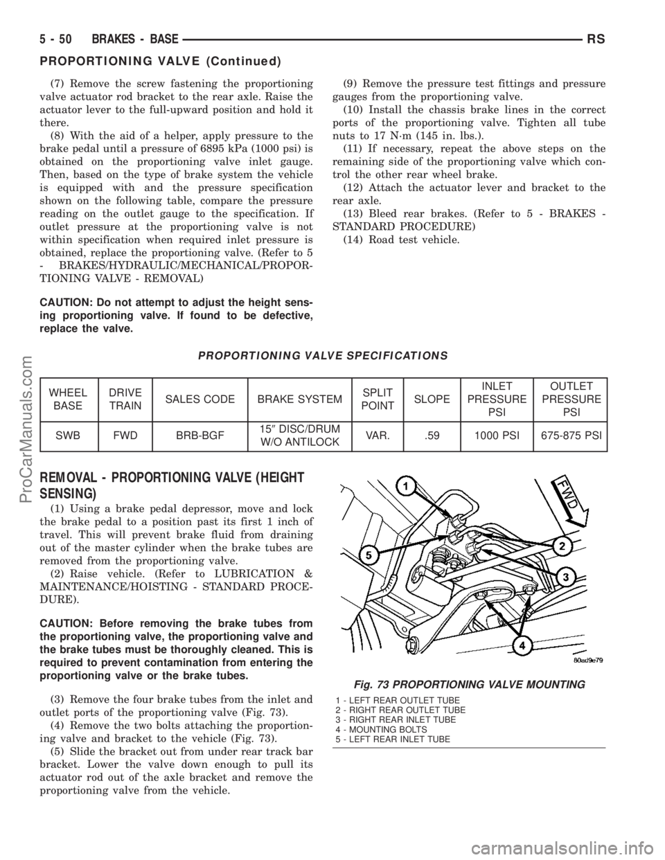
(3) Remove the four brake tubes from the inlet and
outlet ports of the proportioning valve (Fig. 73).
(4) Remove the two bolts attaching the proportion-
ing valve and bracket to the vehicle (Fig. 73).
(5) Slide the bracket out from under rear track bar
bracket. Lower the valve down enough to pull its
actuator rod out of the axle bracket and remove the
proportioning valve from the vehicle.
Fig. 73 PROPORTIONING VALVE MOUNTING
1 - LEFT REAR OUTLET TUBE
2 - RIGHT REAR OUTLET TUBE
3 - RIGHT REAR INLET TUBE
4 - MOUNTING BOLTS
5 - LEFT REAR INLET TUBE
5 - 50 BRAKES - BASERS
PROPORTIONING VALVE (Continued)
ProCarManuals.com
Page 198 of 2177
INSTALLATION - PROPORTIONING VALVE
(HEIGHT SENSING)
(1) Install the end of the actuator rod through the
axle bracket grommet and slide the proportioning
valve bracket under the rear track bar body bracket
(Fig. 73).
(2) Install the proportioning valve attaching bolts
(Fig. 73). Tighten the attaching bolts to a torque of
54 N´m (40 ft. lbs.).
(3) Install the four chassis brake lines into the
inlet and outlet ports of the proportioning valve (Fig.
73). Tighten all tube nuts to a torque of 17 N´m (145
in. lbs.).
CAUTION: The height sensing proportioning valve
is not adjustable. No attempt should be made to
adjust it.
(4) Bleed the brake system thoroughly to ensure
that all air has been expelled from the hydraulic sys-
tem. (Refer to 5 - BRAKES - BASE - STANDARD
PROCEDURE).
(5) Lower the vehicle to the ground.
(6) Road test the vehicle to verify proper operation
of the brake system.
ROTOR
DIAGNOSIS AND TESTING - BRAKE ROTOR
Any servicing of the rotor requires extreme care to
maintain the rotor within service tolerances to
ensure proper brake action.
Excessive runout or wobble in a rotor can increase
pedal travel due to piston knock-back. This increases
guide pin sleeve wear due to the tendency of the cal-
iper to follow the rotor wobble.
When diagnosing a brake noise or pulsation, the
machined disc braking surface should be checked and
inspected.
BRAKING SURFACE INSPECTION
Light braking surface scoring and wear is accept-
able. If heavy scoring or warping is evident, the rotor
must be refaced or replaced. (Refer to 5 - BRAKES/
HYDRAULIC/MECHANICAL/ROTORS - STAN-
DARD PROCEDURE).
Excessive wear and scoring of the rotor can cause
improper lining contact on the rotor's braking sur-
face. If the ridges on the rotor are not removed before
new brake shoes are installed, improper wear of the
shoes will result.
If a vehicle has not been driven for a period of
time, the rotor's braking surface will rust in the
areas not covered by the brake shoes at that time.
Once the vehicle is driven, noise and chatter fromthe disc brakes can result when the brakes are
applied.
Some discoloration or wear of the rotor surface is
normal and does not require resurfacing when lin-
ings are replaced. If cracks or burned spots are evi-
dent, the rotor must be replaced.
ROTOR MINIMUM THICKNESS
Measure rotor thickness at the center of the brake
shoe contact surface. Replace the rotor if it is worn
below minimum thickness or if machining the rotor
will cause its thickness to fall below specifications.
CAUTION: Do not machine the rotor if it will cause
the rotor to fall below minimum thickness.
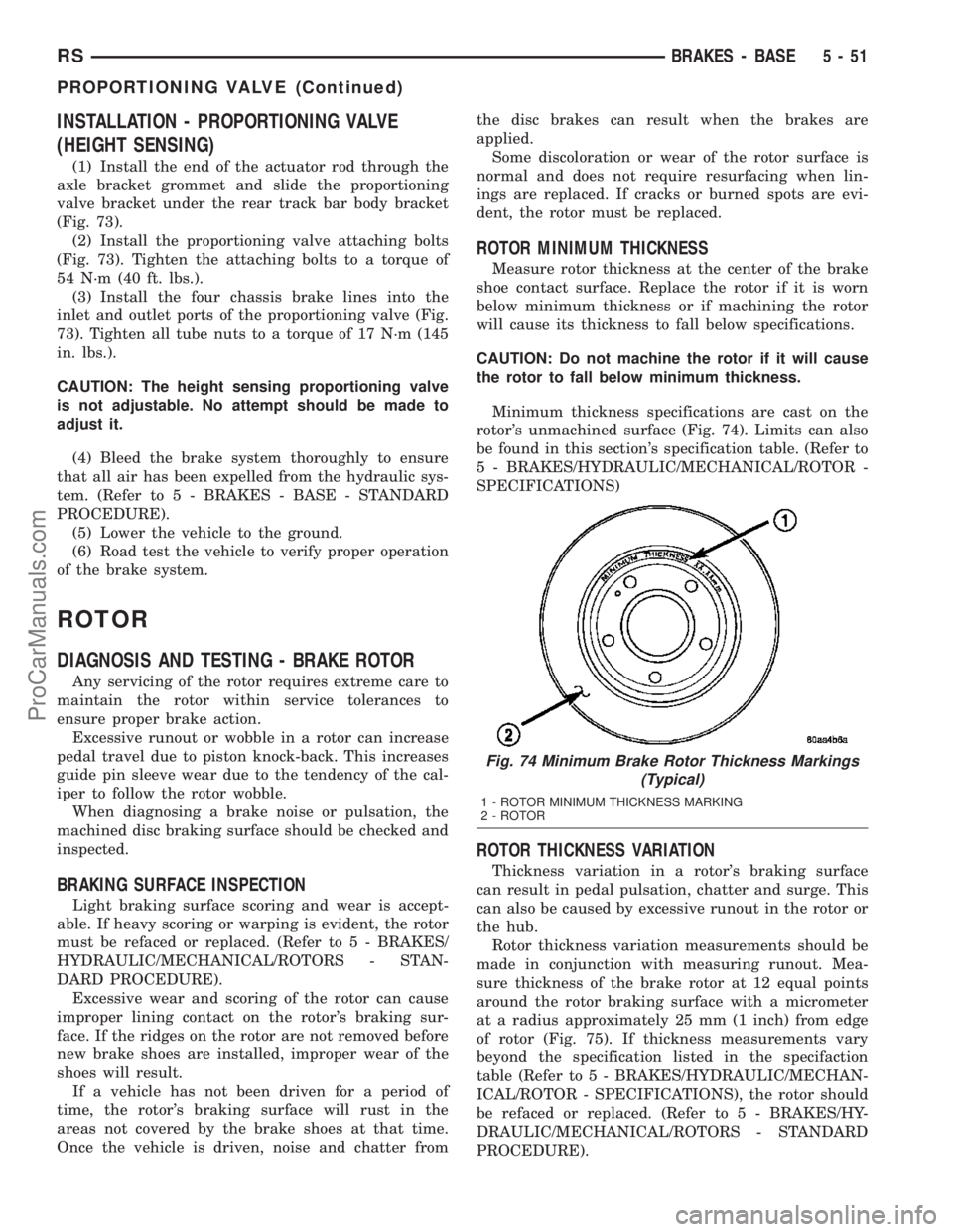
Minimum thickness specifications are cast on the
rotor's unmachined surface (Fig. 74). Limits can also
be found in this section's specification table. (Refer to
5 - BRAKES/HYDRAULIC/MECHANICAL/ROTOR -
SPECIFICATIONS)
ROTOR THICKNESS VARIATION
Thickness variation in a rotor's braking surface
can result in pedal pulsation, chatter and surge. This
can also be caused by excessive runout in the rotor or
the hub.
Rotor thickness variation measurements should be
made in conjunction with measuring runout. Mea-
sure thickness of the brake rotor at 12 equal points
around the rotor braking surface with a micrometer
at a radius approximately 25 mm (1 inch) from edge
of rotor (Fig. 75). If thickness measurements vary
beyond the specification listed in the specifaction
table (Refer to 5 - BRAKES/HYDRAULIC/MECHAN-
ICAL/ROTOR - SPECIFICATIONS), the rotor should
be refaced or replaced. (Refer to 5 - BRAKES/HY-
DRAULIC/MECHANICAL/ROTORS - STANDARD
PROCEDURE).
Fig. 74 Minimum Brake Rotor Thickness Markings
(Typical)
1 - ROTOR MINIMUM THICKNESS MARKING
2 - ROTOR
RSBRAKES - BASE5-51
PROPORTIONING VALVE (Continued)
ProCarManuals.com
Page 522 of 2177

RESTRAINTS
TABLE OF CONTENTS
page page
RESTRAINTS
DESCRIPTION..........................2
OPERATION............................2
WARNING.............................2
DIAGNOSIS AND TESTING - AIRBAG SYSTEM . 2
STANDARD PROCEDURE
STANDARD PROCEDURE - HANDLING
AIRBAGS.............................3
STANDARD PROCEDURE - SERVICE
AFTER AN AIRBAG DEPLOYMENT.........3
CLOCK SPRING
DESCRIPTION..........................4
OPERATION............................4
STANDARD PROCEDURE - CLOCK SPRING
CENTERING..........................4
REMOVAL.............................4
INSTALLATION..........................5
DRIVER AIRBAG
DESCRIPTION..........................5
OPERATION............................5
REMOVAL.............................5
INSTALLATION..........................6
DRIVER AIRBAG TRIM COVER
REMOVAL.............................6
INSTALLATION..........................7
OCCUPANT RESTRAINT CONTROLLER
DESCRIPTION..........................7
OPERATION............................7
REMOVAL.............................7
INSTALLATION..........................7
PASSENGER AIRBAG
DESCRIPTION..........................7
OPERATION............................8
REMOVAL.............................8
INSTALLATION..........................9
SEAT AIRBAG
DESCRIPTION.........................10
OPERATION...........................11
SEAT BELT BUCKLE - FRONT INBOARD
REMOVAL.............................11
INSTALLATION.........................11
SEAT BELT BUCKLE - FIRST ROW INBOARD -
QUAD BUCKET
REMOVAL.............................11
INSTALLATION.........................11
SEAT BELT BUCKLE - FIRST ROW - BENCH
REMOVAL.............................12INSTALLATION.........................12
SEAT BELT BUCKLE - SECOND ROW
INBOARD - 50/50 BENCH
REMOVAL.............................12
INSTALLATION.........................12
SEAT BELT HEIGHT ADJUSTER-BOR
C-PILLAR
REMOVAL.............................12
INSTALLATION.........................12
SEAT BELT HEIGHT ADJUSTER KNOB
REMOVAL.............................13
INSTALLATION.........................13
SEAT BELT & RETRACTOR - OUTBOARD -
FRONT
REMOVAL.............................13
INSTALLATION.........................13
SEAT BELT & RETRACTOR - FIRST ROW -
OUTBOARD
REMOVAL.............................13
INSTALLATION.........................13
SEAT BELT BUCKLE - SECOND ROW - THREE
PASSENGER BENCH
REMOVAL.............................14
INSTALLATION.........................14
SEAT BELT & RETRACTOR - SECOND ROW -
RIGHT OUTBOARD
REMOVAL.............................14
INSTALLATION.........................14
SEAT BELT & RETRACTOR - SECOND ROW -
RIGHT OUTBOARD WITH REAR HVAC - LWB
REMOVAL.............................15
INSTALLATION.........................15
SEAT BELT & RETRACTOR - SECOND ROW -
LEFT OUTBOARD
REMOVAL.............................16
INSTALLATION.........................16
SEAT BELT TENSIONER
DESCRIPTION.........................16
OPERATION...........................16
SIDE IMPACT AIRBAG CONTROL MODULE
DESCRIPTION.........................17
OPERATION...........................17
REMOVAL.............................17
INSTALLATION.........................17
RSRESTRAINTS8O-1
ProCarManuals.com
Page 533 of 2177
SEAT BELT BUCKLE - FIRST
ROW - BENCH
REMOVAL
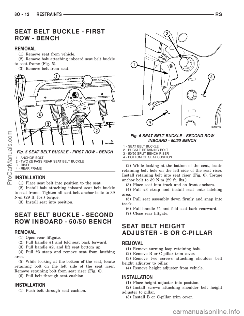
(1) Remove seat from vehicle.
(2) Remove bolt attaching inboard seat belt buckle
to seat frame (Fig. 5).
(3) Remove belt from seat.
INSTALLATION
(1) Place seat belt into position to the seat.
(2) Install bolt attaching inboard seat belt buckle
to seat frame. Tighten all seat belt anchor bolts to 39
N´m (29 ft. lbs.) torque.
(3) Install seat into position.
SEAT BELT BUCKLE - SECOND
ROW INBOARD - 50/50 BENCH
REMOVAL
(1) Open rear liftgate.
(2) Pull handle #1 and fold seat back forward.
(3) Pull handle #2, and lift seat bottom up.
(4) Pull #3 strap and remove seat from latching
area.
(5) While looking at the bottom of the seat, locate
retaining bolt on the left side of the seat riser.
Remove retaining bolt from seat riser (Fig. 6).
(6) Pull belt through seat cushion.
INSTALLATION
(1) Push belt through seat cushion.(2) While looking at the bottom of the seat, locate
retaining bolt hole on the left side of the seat riser.
Install retaining bolt into seat riser (Fig. 6). Torque
anchor bolt to 39 N´m (29 ft. lbs.).
(3) Place seat into track and on front anchors.
(4) Pull #3 strap and install seat onto latching
area.
(5) Pull seat assembly down firmly and snap into
track.
(6) Pull handle #1 and fold seat back rearward.
(7) Close rear liftgate.
SEAT BELT HEIGHT
ADJUSTER-BORC-PILLAR
REMOVAL
(1) Remove turning loop retaining bolt.
(2) Remove B or C-pillar trim cover.
(3) Remove two screws attaching shoulder belt
height adjuster to pillar.
(4) Remove height adjuster from vehicle.
INSTALLATION
(1) Place height adjuster into position.
(2) Install screws attaching shoulder belt height
adjuster to pillar.
(3) Install B or C-pillar trim cover.
Fig. 5 SEAT BELT BUCKLE - FIRST ROW - BENCH
1 - ANCHOR BOLT
2 - TWO (2) PASS REAR SEAT BELT BUCKLE
3 - RISER
4 - REAR FRAME
Fig. 6 SEAT BELT BUCKLE - SECOND ROW
INBOARD - 50/50 BENCH
1 - SEAT BELT BUCKLE
2 - BUCKLE RETAINING BOLT
3 - 50/50 SPLIT BENCH RISER
4 - BOTTOM OF SEAT CUSHION
8O - 12 RESTRAINTSRS
ProCarManuals.com
Page 534 of 2177
(4) Install turning loop to height adjuster. Torque
anchor bolt to 39 N´m (29 ft. lbs.).
SEAT BELT HEIGHT
ADJUSTER KNOB
REMOVAL
(1) Disengage clips attaching clam shell cover to
seat belt turning loop and open cover.
(2) Using a trim tool (special tool #C-4755), gently
pry knob from seat belt height adjuster.
INSTALLATION
(1) Place seat belt height adjuster knob in position
on height adjuster.
(2) Firmly push knob on until retainers engage.
(3) Reinstall turning loop clam shell cover.
(4) Verify seat belt operation. Make sure it moves
through loop without binding.
SEAT BELT & RETRACTOR -
OUTBOARD - FRONT
REMOVAL
(1) Open door.
(2) Move seat all the way forward.
(3) Open hood.
(4) Disconnect and isolate the negative battery
cable.
(5) Remove shoulder harness height adjuster knob
by pulling it straight away from adjuster.
(6) Remove cover from seat belt turning loop.
(7) Remove bolt attaching turning loop to shoulder
belt height adjuster.
(8) Remove upper B-pillar trim cover.
(9) Remove the lower seat belt anchor bolt.
(10) Remove front door sill plate.
(11) Remove sliding door sill plate.
(12) Remove lower B-pillar trim cover.
(13) Disconnect the seat belt retractor electrical
connector.
(14) Remove seat belt retractor attaching bolt.
(15) Remove the seat belt and retractor from vehi-
cle.
INSTALLATION
Inspect the condition of the shoulder belt and lap
belt. Replace any belt that is cut, frayed, torn, or
damaged in any way. Also, replace the shoulder belt
if the retractor is either damaged or inoperative.
(1) Place seat belt and retractor into position.
(2) Install bolt attaching seat belt retractor to
B-pillar. Torque bolt to 39 N´m (29 ft. lbs.).(3) Connect the seat belt retractor electrical con-
nector.
(4) Install the lower B-pillar trim cover.
(5) Install the sliding door sill plate.
(6) Install the front door sill plate.
(7) Install the lower seat belt anchor bolt. Torque
bolt to 39 N´m (29 ft. lbs.).
(8) Install the upper B-pillar trim cover.
(9) Install the bolt attaching turning loop to shoul-
der belt height adjuster. Torque bolt to 39 N´m (29 ft.
lbs.).
(10) Install the cover to the seat belt turning loop.
(11) Install the shoulder harness height adjuster
knob by pushing it straight onto the adjuster.
(12) Connect the battery negative cable.
(13) Verify vehicle and system operation.
(14) Move seat back to approximate customer posi-
tion.
(15) Close hood and door.
SEAT BELT & RETRACTOR -
FIRST ROW - OUTBOARD
REMOVAL
(1) Remove first and second row seats.
(2) Remove first row seat belt lower anchor bolt.
(3) Remove first row seat belt upper turning loop
anchor bolt.
(4) Remove liftgate sill plate.
(5) Remove upper liftgate trim.
(6) Remove second seat lower anchor bolt.
(7) Remove second seat upper turning loop anchor
bolt.
(8) Remove D-pillar trim cover.
(9) Disconnect speaker connector. The left side has
the speaker mounted in the D-pillar trim cover and
the right side will have the speaker mounted in the
rear of the quarter trim panel, but the connector is
accessible from the rear after the D-pillar trim is
removed.
(10) Remove quarter trim bolster.
(11) Remove quarter trim panel screws.
(12) Remove quarter trim panel.
(13) Remove first row seat belt and retractor
retaining bolt.
(14) Remove first row seat belt and retractor from
vehicle.
INSTALLATION
(1) Install first row seat belt and retractor. Torque
bolt to 39 N´m (29 ft. lbs.).
(2) Install quarter trim panel.
(3) Install quarter trim panel screws.
(4) Install quarter trim bolster.
RSRESTRAINTS8O-13
SEAT BELT HEIGHT ADJUSTER-BORC-PILLAR (Continued)
ProCarManuals.com
Page 1197 of 2177
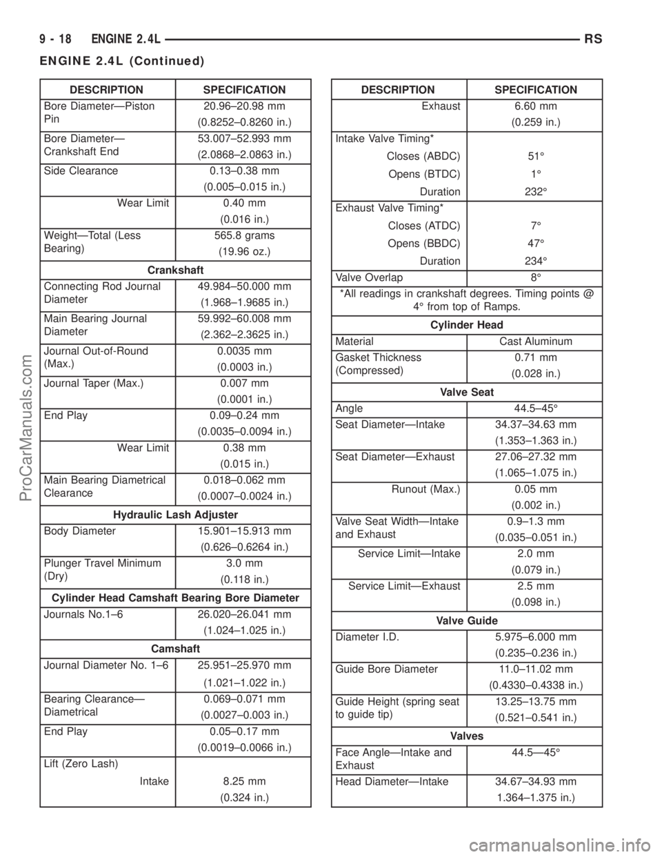
DESCRIPTION SPECIFICATION
Bore DiameterÐPiston
Pin20.96±20.98 mm
(0.8252±0.8260 in.)
Bore DiameterÐ
Crankshaft End53.007±52.993 mm
(2.0868±2.0863 in.)
Side Clearance 0.13±0.38 mm
(0.005±0.015 in.)
Wear Limit 0.40 mm
(0.016 in.)
WeightÐTotal (Less
Bearing)565.8 grams
(19.96 oz.)
Crankshaft
Connecting Rod Journal
Diameter49.984±50.000 mm
(1.968±1.9685 in.)
Main Bearing Journal
Diameter59.992±60.008 mm
(2.362±2.3625 in.)
Journal Out-of-Round
(Max.)0.0035 mm
(0.0003 in.)
Journal Taper (Max.) 0.007 mm
(0.0001 in.)
End Play 0.09±0.24 mm
(0.0035±0.0094 in.)
Wear Limit 0.38 mm
(0.015 in.)
Main Bearing Diametrical
Clearance0.018±0.062 mm
(0.0007±0.0024 in.)
Hydraulic Lash Adjuster
Body Diameter 15.901±15.913 mm
(0.626±0.6264 in.)
Plunger Travel Minimum
(Dry)3.0 mm
(0.118 in.)
Cylinder Head Camshaft Bearing Bore Diameter
Journals No.1±6 26.020±26.041 mm
(1.024±1.025 in.)
Camshaft
Journal Diameter No. 1±6 25.951±25.970 mm
(1.021±1.022 in.)
Bearing ClearanceÐ
Diametrical0.069±0.071 mm
(0.0027±0.003 in.)
End Play 0.05±0.17 mm
(0.0019±0.0066 in.)
Lift (Zero Lash)
Intake 8.25 mm
(0.324 in.)DESCRIPTION SPECIFICATION
Exhaust 6.60 mm
(0.259 in.)
Intake Valve Timing*
Closes (ABDC) 51É
Opens (BTDC) 1É
Duration 232É
Exhaust Valve Timing*
Closes (ATDC) 7É
Opens (BBDC) 47É
Duration 234É
Valve Overlap 8É
*All readings in crankshaft degrees. Timing points @
4É from top of Ramps.
Cylinder Head
Material Cast Aluminum
Gasket Thickness
(Compressed)0.71 mm
(0.028 in.)
Valve Seat
Angle 44.5±45É
Seat DiameterÐIntake 34.37±34.63 mm
(1.353±1.363 in.)
Seat DiameterÐExhaust 27.06±27.32 mm
(1.065±1.075 in.)
Runout (Max.) 0.05 mm
(0.002 in.)
Valve Seat WidthÐIntake
and Exhaust0.9±1.3 mm
(0.035±0.051 in.)
Service LimitÐIntake 2.0 mm
(0.079 in.)
Service LimitÐExhaust 2.5 mm
(0.098 in.)
Valve Guide
Diameter I.D. 5.975±6.000 mm
(0.235±0.236 in.)
Guide Bore Diameter 11.0±11.02 mm
(0.4330±0.4338 in.)
Guide Height (spring seat
to guide tip)13.25±13.75 mm
(0.521±0.541 in.)
Valves
Face AngleÐIntake and
Exhaust44.5Ð45É
Head DiameterÐIntake 34.67±34.93 mm
1.364±1.375 in.)
9 - 18 ENGINE 2.4LRS
ENGINE 2.4L (Continued)
ProCarManuals.com
Page 1198 of 2177

DESCRIPTION SPECIFICATION
Head DiameterÐExhaust 28.32±28.52 mm
(1.114±1.122 in.)
Valve Length (Overall)
ÐIntake 112.76±113.32 mm
(4.439±4.461 in.)
ÐExhaust 110.89±111.69 mm
(4.365±4.397 in.)
Valve Stem Diameter
ÐIntake 5.934±5.952 mm
(0.2337±0.2344 in.)
ÐExhaust 5.906±5.924 mm
(0.2326±0.2333 in.)
Valve Margin
Intake 1.2±1.7 mm
(0.047±0.066 in.)
Service Limit 0.95 mm
(1/32 in.)
Exhaust 0.985±1.315 mm
(0.038±0.051 in.)
Service Limit 1.05 mm
(3/64 in.)
Valve Stem Tip Height
Intake 48.04 mm
(1.891 in.)
Exhaust 47.99 mm
(1.889 in.)
Valve Stem to Guide Clearance
Intake 0.048±0.066 mm
(0.0018±0.0025 in.)
Max. Allowable 0.076 mm
(0.003 in.)
Service Limit 0.25 mm
(0.010 in.)
Exhaust 0.0736±0.094 mm
(0.0029±0.0037 in.)
Max. Allowable 0.101 mm
(0.004 in.)
Service Limit 0.25 mm
(0.010 in.)DESCRIPTION SPECIFICATION
Valve Springs
Free Length (Approx.) 48.4 mm
(1.905 in.)
Nominal Force (Valve
Closed)338 N @ 38.0 mm
(75.98 lbs. @ 1.496 in.)
Nominal Force (Valve
Open)607 N @ 29.75 mm
(136 lbs. @ 1.172 in.)
Installed Height 38.00 mm
(1.496 in.)
Number of Coils 7.82
Wire Diameter 3.86 mm
(1.496 in.)
Oil Pump
Clearance Over Rotors
(Max.)0.10 mm
(0.004 in.)
Cover Out-of-Flat (Max.) 0.025 mm
(0.001 in.)
Inner Rotor Thickness
(Min.)9.40 mm
(0.370 in.)
Outer Rotor Thickness
(Min.)9.40 mm
(0.370 in.)
Outer Rotor Clearance
(Max.)0.039 mm
(0.015 in.)
Outer Rotor Diameter
(Min.)79.95 mm
(3.148 in.)
Tip Clearance Between
Rotors (Max.)0.20 mm
(0.008 in.)
Oil Pressure
At Curb Idle Speed* 25 kPa
(4 psi)
At 3000 rpm 170±550 kPa
(25±80 psi)
CAUTION:
*If pressure is ZERO at curb idle, DO NOT run engine
at 3000 rpm.
RSENGINE 2.4L9-19
ENGINE 2.4L (Continued)
ProCarManuals.com
Page 1205 of 2177

(15) Remove cylinder head cover. (Refer to 9 -
ENGINE/CYLINDER HEAD/CYLINDER HEAD
COVER(S) - REMOVAL)
(16) Remove camshafts (Refer to 9 - ENGINE/
CYLINDER HEAD/CAMSHAFT(S) - REMOVAL).
NOTE: Identify rocker arm position to ensure cor-
rect re-installation in original position, if reused.
(17) Remove rocker arms. (Refer to 9 - ENGINE/
CYLINDER HEAD/ROCKER ARMS - REMOVAL)
(18) Remove cylinder head bolts in REVERSE
sequence of tightening (Fig. 19).
(19) Remove cylinder head from engine block.
(20) Inspect and clean cylinder head. (Refer to 9 -
ENGINE/CYLINDER HEAD - INSPECTION) (Refer
to 9 - ENGINE/CYLINDER HEAD - CLEANING)
CLEANING
To ensure engine gasket sealing, proper surface
preparation must be performed, especially with the
use of aluminum engine components and multi-layer
steel cylinder head gaskets.
NOTE: Multi-Layer Steel (MLS) head gaskets require
a scratch free sealing surface.
Remove all gasket material from cylinder head and
block (Refer to 9 - ENGINE - STANDARD PROCE-
DURE). Be careful not to gouge or scratch the alumi-
num head sealing surface.
Clean all engine oil passages.
INSPECTION
(1) Cylinder head must be flat within 0.1 mm
(0.004 in.) (Fig. 14).
(2) Inspect camshaft bearing journals for scoring.(3) Remove carbon and varnish deposits from
inside of valve guides with a reliable guide cleaner.
(4) Using a small hole gauge and a micrometer,
measure valve guides in 3 places top, middle and bot-
tom (Fig. 15). (Refer to 9 - ENGINE - SPECIFICA-
TIONS) Replace guides if they are not within
specification.
(5) Check valve guide height (Fig. 16).
INSTALLATION - CYLINDER HEAD
NOTE: The Cylinder head bolts should be examined
BEFORE reuse. If the threads are necked down, the
bolts must be replaced (Fig. 17).
Necking can be checked by holding a scale or
straight edge against the threads. If all the threads
do not contact the scale, the bolt should be replaced.
(1) Before installing the bolts, the threads should
be coated with engine oil.
Fig. 14 Checking Cylinder Head Flatness
1 - FEELER GAUGE
2 - STRAIGHT EDGE
Fig. 15 Checking Wear on Valve GuideÐTypical
1-TOP
2 - MIDDLE
3 - BOTTOM
4 - CUT AWAY VIEW OF VALVE GUIDE MEASUREMENT
LOCATIONS
Fig. 16 Valve Guide Height
1 - VALVE GUIDE
2 - 13.25 - 13.75 MM (0.521 - 0.541 IN.)
3 - SPRING SEAT
9 - 26 ENGINE 2.4LRS
CYLINDER HEAD (Continued)
ProCarManuals.com
Page 1212 of 2177

INSTALLATION
INSTALLATION - CYLINDER HEAD ON
(1) Install valve seal/valve spring seat assembly
(Fig. 34). Push the assembly down to seat it onto the
valve guide.
(2) Install valve spring and retainer, use Special
Tool MD-998772-A with adapter 6779 to compress
valve springs only enough to install locks (Fig. 33).
Correct alignment of tool is necessary to avoid nick-
ing valve stems.
(3) Remove air hose and install spark plugs.
(4) Install camshafts (Refer to 9 - ENGINE/CYL-
INDER HEAD/CAMSHAFT(S) - INSTALLATION).
(5) Install cylinder head cover (Refer to 9 -
ENGINE/CYLINDER HEAD/CYLINDER HEAD
COVER - INSTALLATION).
INSTALLATION - CYLINDER HEAD OFF
(1) Coat valve stems with clean engine oil and
insert in cylinder head.
(2) Install new valve stem seals on all valves
using a valve stem seal tool (Fig. 35). The valve stem
seals should be pushed firmly and squarely over
valve guide.
CAUTION: When oversize valves are used, the cor-
responding oversize valve seal must also be used.
Excessive guide wear may result if oversize seals
are not used with oversize valves.(3) Install valve springs and retainers. Compress
valve springs only enough to install locks, taking
care not to misalign the direction of compression.
Nicked valve stems may result from misalignment of
the valve spring compressor.
CAUTION: When depressing the valve spring retain-
ers with valve spring compressor the locks can
become dislocated. Ensure both locks are in the
correct location after removing tool.
(4) Check the valve spring installed height B after
refacing the valve and seat (Fig. 36). Make sure mea-
surements are taken from top of spring seat to the
bottom surface of spring retainer. If height is greater
than 38.75 mm (1.525 in.), install a 0.762 mm (0.030
in.) spacer under the valve spring seat to bring
spring height back within specification.
Fig. 34 Valve Stem Seal/Valve Spring Seat
1 - VALVE RETAINING LOCKS
2 - VALVE SPRING
3 - VALVE SEAL AND VALVE SPRING SEAT ASSEMBLY
4 - VALVE SPRING RETAINER
Fig. 35 Valve Stem Oil Seal Tool
1 - VALVE SEAL TOOL
2 - VALVE STEM
Fig. 36 Checking Spring Installed Height and Valve
Tip Height Dimensions
1 - GARTER SPRING
2 - VALVE SPRING SEAT
3 - CYLINDER HEAD SURFACE
RSENGINE 2.4L9-33
VALVE SPRINGS & SEALS (Continued)
ProCarManuals.com