Windows CHRYSLER VOYAGER 2003 Owner's Manual
[x] Cancel search | Manufacturer: CHRYSLER, Model Year: 2003, Model line: VOYAGER, Model: CHRYSLER VOYAGER 2003Pages: 2177, PDF Size: 59.81 MB
Page 2070 of 2177
NOTE: Liquid CO2is required to test the expansion
valve. This material is available from most welding
supply facilities. Liquid CO
2is also available from
companies which service and sell fire extinguish-
ers.
When testing the expansion valve, the work area
and the vehicle temperature must be 21É to 27É C
(70É to 85É F). To test the expansion valve:
(1) Connect a charging station or manifold gauge
set to the refrigerant system service ports. Verify the
refrigerant charge level.
(2) Close all doors, windows and vents to the pas-
senger compartment.
(3) Set the heater-air conditioner controls so that
the compressor is operating, the temperature control
is in the highest temperature position, the mode door
is directing the output to the floor outlets, and the
blower is operating at the highest speed setting.
(4) Start the engine and allow it to idle at 1000
rpm. After the engine has reached normal operating
temperature, allow the passenger compartment to
heat up. This will create the need for maximum
refrigerant flow into the evaporator.
(5) If the refrigerant charge is sufficient, the dis-
charge (high pressure) gauge should read 965 to 1655
kPa (140 to 240 psi). The suction (low pressure)
gauge should read 140 kPa to 207 kPa (20 psi to 30
psi). If OK, go to Step 6. If not OK, replace the faulty
expansion valve.
WARNING:
PROTECT THE SKIN AND EYES FROM EXPOSURE
TO LIQUID CO
2. PERSONAL INJURY CAN RESULT.
(6) If the suction (low pressure) gauge reads
within the specified range, freeze the expansion valve
control head for 30 seconds using liquid CO
2or
another suitable super-cold material.Do not spray
R-134a or R-12 refrigerant on the expansion
valve control head for this test.The suction (low
pressure) gauge reading should drop by 10 psi. If OK,
go to Step 7 If not OK, replace the faulty expansion
valve.
(7) Allow the expansion valve control head to thaw.
The suction (low pressure) gauge reading should sta-
bilize at 140 kPa to 240 kPa (20 psi to 30 psi). If not
OK, replace the faulty expansion valve.
(8) When expansion valve testing is complete, test
the overall air conditioner performance. (Refer to 24 -
HEATING & AIR CONDITIONING - DIAGNOSIS
AND TESTING - A/C PERFORMANCE TEST).
Remove all test equipment before returning the vehi-
cle to service.
REMOVAL
WARNING: REFER TO THE APPLICABLE WARN-
INGS AND CAUTIONS FOR THIS SYSTEM BEFORE
PERFORMING THE FOLLOWING OPERATION.
(Refer to 24 - HEATING & AIR CONDITIONING/
PLUMBING - FRONT - WARNING - A/C PLUMBING)
and (Refer to 24 - HEATING & AIR CONDITIONING/
PLUMBING - FRONT - CAUTION - A/C PLUMBING).
(1) Recover the refrigerant from the refrigerant
system. (Refer to 24 - HEATING & AIR CONDI-
TIONING/PLUMBING - FRONT/REFRIGERANT -
STANDARD PROCEDURE - REFRIGERANT
RECOVERY).
(2) Disconnect and isolate the battery negative
cable.
(3) Remove the air cleaner housing from the right
side of the engine compartment.
(4) Disconnect the drain tube from the wiper mod-
ule drain on the right side of the engine compart-
ment.
(5) Disconnect the headlamp and dash wire har-
ness connector for the A/C pressure transducer from
the transducer on the front liquid line rear section
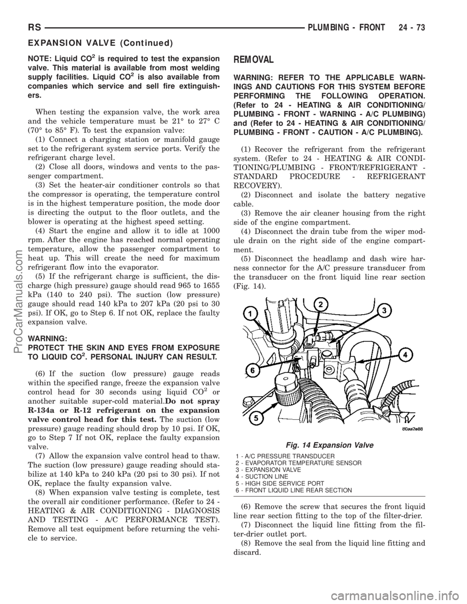
(Fig. 14).
(6) Remove the screw that secures the front liquid
line rear section fitting to the top of the filter-drier.
(7) Disconnect the liquid line fitting from the fil-
ter-drier outlet port.
(8) Remove the seal from the liquid line fitting and
discard.
Fig. 14 Expansion Valve
1 - A/C PRESSURE TRANSDUCER
2 - EVAPORATOR TEMPERATURE SENSOR
3 - EXPANSION VALVE
4 - SUCTION LINE
5 - HIGH SIDE SERVICE PORT
6 - FRONT LIQUID LINE REAR SECTION
RSPLUMBING - FRONT24-73
EXPANSION VALVE (Continued)
ProCarManuals.com
Page 2083 of 2177
K thermocouple. If a digital multimeter is not avail-
able, this tool is also available through the PSE pro-
gram.
NOTE: When connecting the service equipment
couplings to the refrigerant system service ports,
be certain that the valve of each coupling is fully
closed. This will reduce the amount of effort
required to make the connection.
(1) Remove the caps from the refrigerant system
service ports and attach a manifold gauge set or a
R-134a refrigerant recovery/recycling/charging sta-
tion that meets SAE Standard J2210 to the refriger-
ant system.
(2) Attach a clamp-on thermocouple to the liquid
line. The thermocouple must be placed as close to the
A/C pressure transducer as possible to accurately
observe liquid line temperature.
(3) Bring the refrigerant system up to operating
temperature and pressure. This is done by allowing
the engine to run at idle under the following condi-
tions for five minutes.
(a) Front windows are open.
(b) Transaxle in Park.
(c) Front heater-A/C controls set to outside air,
full cool, panel mode, blower high, and compressor
engaged.
(d) If the vehicle is so equipped, the rear heater-
A/C controls must be set to full cool and blower
high.
(4) Raise the liquid line (discharge) pressure to
about 1793 kPa (260 psi) by placing a piece of card-
board over part of the front side of the condenser. To
place the cardboard properly, remove the upper radi-
ator sight shield from the front fascia. Cover only
enough of the condenser to raise and maintain the
liquid line pressure at the specified level.
(5) Observe the liquid line (discharge) pressure
and liquid line temperature. Using the Charge Deter-
mination Chart (Fig. 31), determine whether the
refrigerant system is operating within the Proper
Charge Range.
(a) If the refrigerant system is operating in the
Undercharged area of the chart, add 0.057 kilo-
gram (0.125 pound or 2 ounces) of refrigerant to
the system.
(b) If the refrigerant system is operating in the
Overcharged area of the chart, reclaim 0.057 kilo-
gram (0.125 pound or 2 ounces) of refrigerant from
the system.
(6) Recheck the system charge level following each
refrigerant adjustment. Continue this process until
the system readings are in the Proper Charge Range
area on the Charge Determination Chart.DIAGNOSIS AND TESTING - REFRIGERANT
SYSTEM LEAKS
WARNING: REFER TO THE APPLICABLE WARN-
INGS AND CAUTIONS FOR THIS SYSTEM BEFORE
PERFORMING THE FOLLOWING OPERATION.
(Refer to 24 - HEATING & AIR CONDITIONING/
PLUMBING - FRONT - WARNING - A/C PLUMBING)
and (Refer to 24 - HEATING & AIR CONDITIONING/
PLUMBING - FRONT - CAUTION - A/C PLUMBING).
If the air conditioning system is not cooling prop-
erly, determine if the refrigerant system is fully-
charged. (Refer to 24 - HEATING & AIR
CONDITIONING/PLUMBING - FRONT/REFRIGER-
ANT - DIAGNOSIS AND TESTING - REFRIGER-
ANT SYSTEM CHARGE LEVEL).
If the refrigerant system is low or empty; a leak at
a refrigerant line, connector fitting, component, or
component seal is likely. While an oily residue on or
near refrigerant system lines, connector fittings, com-
ponents, or component seals can indicate the general
location of a possible refrigerant leak, the exact leak
location should be confirmed with an electronic leak
detector prior to component repair or replacement.
An electronic leak detector designed for R-134a
refrigerant is recommended for locating and confirm-
ing refrigerant system leaks. See the operating
instructions supplied by the equipment manufacturer
for proper care and use of this equipment.
To detect a leak in the refrigerant system, perform
one of the following procedures as indicated by the
results of the refrigerant system charge level test.
SYSTEM EMPTY
(1) Evacuate the refrigerant system. (Refer to 24 -
HEATING & AIR CONDITIONING/PLUMBING -
FRONT/REFRIGERANT - STANDARD PROCE-
DURE - REFRIGERANT SYSTEM EVACUATE).
(2) Connect and dispense 0.283 kilograms (0.625
pounds or 10 ounces) of R-134a refrigerant into the
evacuated refrigerant system. (Refer to 24 - HEAT-
ING & AIR CONDITIONING/PLUMBING - FRONT/
REFRIGERANT - STANDARD PROCEDURE -
REFRIGERANT SYSTEM CHARGE).
(3) Proceed to the SYSTEM LOW procedures.
SYSTEM LOW
(1) Position the vehicle in a wind-free work area.
This will aid in detecting small leaks.
(2) Bring the refrigerant system up to operating
temperature and pressure. This is done by allowing
the engine to run at idle under the following condi-
tions for five minutes, then turning the engine off.
(a) Front windows are open.
(b) Rear air conditioner Off (if equipped).
24 - 86 PLUMBING - FRONTRS
REFRIGERANT (Continued)
ProCarManuals.com
Page 2086 of 2177
(4) Open both the suction and discharge valves,
then open the charge valve to allow the heated
refrigerant to flow into the system.
(5) When the transfer of refrigerant has stopped,
close both the suction and discharge valves.
(6) If all of the refrigerant charge did not transfer
from the dispensing device, open all of the windows
in the vehicle and set the heater-air conditioner con-
trols so that the compressor is engaged and the
blower motor is operating at its lowest speed setting.
Run the engine at a steady high idle (about 1400
rpm). If the compressor will not engage, test the com-
pressor clutch control circuit and repair as required.
(7) Open the suction valve to allow the remaining
refrigerant to transfer to the refrigerant system.
WARNING: TAKE CARE NOT TO OPEN THE DIS-
CHARGE (HIGH PRESSURE) VALVE AT THIS TIME.
(8) Close the suction valve and test the system
performance. (Refer to 24 - HEATING & AIR CON-
DITIONING - STANDARD PROCEDURE - A/C PER-
FORMANCE TEST).
(9) Disconnect the charging station and manifold
gauge set from the refrigerant system service ports.
(10) Reinstall the caps onto the refrigerant system
service ports.
(11) Run the HVAC Control Cooldown test to ver-
ify proper operation(Refer to 24 - HEATING & AIR
CONDITIONING - DIAGNOSIS AND TESTING).
STANDARD PROCEDURE - REFRIGERANT
SYSTEM EVACUATE
WARNING: REFER TO THE APPLICABLE WARN-
INGS AND CAUTIONS FOR THIS SYSTEM BEFORE
PERFORMING THE FOLLOWING OPERATION.
(Refer to 24 - HEATING & AIR CONDITIONING/
PLUMBING - FRONT - WARNING - A/C PLUMBING)
and (Refer to 24 - HEATING & AIR CONDITIONING/
PLUMBING - FRONT - CAUTION - A/C PLUMBING).
If the refrigerant system has been open to the
atmosphere, it must be evacuated before the system
can be charged. If moisture and air enters the system
and becomes mixed with the refrigerant, the com-
pressor head pressure will rise above acceptable
operating levels. This will reduce the performance of
the air conditioner and damage the compressor.
Evacuating the refrigerant system will remove the
air and boil the moisture out of the system at near
room temperature. A R-134a refrigerant recovery/re-
cycling/charging station that meets SAE Standard
J2210 must be used to evacuate the refrigerant sys-
tem. See the operating instructions supplied by the
equipment manufacturer for proper care and use ofthis equipment. To evacuate the refrigerant system,
use the following procedure:
NOTE: When connecting the service equipment
couplings to the refrigerant system service ports,
be certain that the valve of each coupling is fully
closed. This will reduce the amount of effort
required to make the connection.
(1) Remove the caps from the refrigerant system
service ports and attach a manifold gauge set and a
R-134a refrigerant recovery/recycling/charging sta-
tion that meets SAE Standard J2210 to the refriger-
ant system.
(2) Open both the suction and discharge valves
and start the charging station vacuum pump.
(3) When the suction gauge has read 88 kPa (26
in. Hg.) vacuum or greater for 45 minutes, close both
the suction and discharge valves and turn off the
vacuum pump. If the refrigerant system fails to
reach the specified vacuum, the system has a leak
that must be corrected. (Refer to 24 - HEATING &
AIR CONDITIONING/PLUMBING - FRONT/RE-
FRIGERANT - STANDARD PROCEDURE -
REFRIGERANT SYSTEM LEAKS).
(4) If the refrigerant system maintains the speci-
fied vacuum for thirty minutes, restart the vacuum
pump, open both the suction and discharge valves,
and evacuate the system for an additional ten min-
utes.
(5) Close both the suction and discharge valves,
and turn off the charging station vacuum pump.
(6) The refrigerant system is now ready to be
charged with R-134a refrigerant. (Refer to 24 -
HEATING & AIR CONDITIONING/PLUMBING -
FRONT/REFRIGERANT - STANDARD PROCE-
DURE - REFRIGERANT SYSTEM CHARGE).
STANDARD PROCEDURE - REFRIGERANT
RECOVERY
WARNING: REFER TO THE APPLICABLE WARN-
INGS AND CAUTIONS FOR THIS SYSTEM BEFORE
PERFORMING THE FOLLOWING OPERATION.
(Refer to 24 - HEATING & AIR CONDITIONING/
PLUMBING - FRONT - WARNING - A/C PLUMBING)
and (Refer to 24 - HEATING & AIR CONDITIONING/
PLUMBING - FRONT - CAUTION - A/C PLUMBING).
A R-134a refrigerant recovery/recycling/charging
station that meets SAE Standard J2210 must be
used to recover the refrigerant from an R-134a refrig-
erant system, whenever the refrigerant system must
be opened for service. See the operating instructions
supplied by the equipment manufacturer for the
proper care and use of this equipment.
RSPLUMBING - FRONT24-89
REFRIGERANT (Continued)
ProCarManuals.com
Page 2094 of 2177
OPERATION
A mechanical sensor in the expansion valve control
head monitors the temperature and pressure of the
refrigerant leaving the evaporator coil through the
suction line, and adjusts the orifice size at the liquid
line to let the proper amount of refrigerant into the
evaporator coil to meet the vehicle cooling require-
ments. Controlling the refrigerant flow through the
evaporator ensures that none of the refrigerant leav-
ing the evaporator is still in a liquid state, which
could damage the compressor.
DIAGNOSIS AND TESTING - EXPANSION VALVE
WARNING: REFER TO THE APPLICABLE WARN-
INGS AND CAUTIONS FOR THIS SYSTEM BEFORE
PERFORMING THE FOLLOWING OPERATION.
(Refer to 24 - HEATING & AIR CONDITIONING/
PLUMBING - FRONT - WARNING - A/C PLUMBING)
and (Refer to 24 - HEATING & AIR CONDITIONING/
PLUMBING - FRONT - CAUTION - A/C PLUMBING).
NOTE: The expansion valve should only be tested
following testing of the compressor.
NOTE: Liquid CO
2is required to test the expansion
valve. This material is available from most welding
supply facilities. Liquid CO
2is also available from
companies which service and sell fire extinguish-
ers.
When testing the expansion valve, the work area
and the vehicle temperature must be 21É to 27É C
(70É to 85É F). To test the expansion valve:
(1) Connect a charging station or manifold gauge
set to the refrigerant system service ports. Verify the
refrigerant charge level.
(2) Close all doors, windows and vents to the pas-
senger compartment.
(3) Set the heater-air conditioner controls so that
the compressor is operating, the temperature control
is in the highest temperature position, the mode door
is directing the output to the floor outlets, and the
blower is operating at the highest speed setting.
(4) Start the engine and allow it to idle at 1000
rpm. After the engine has reached normal operating
temperature, allow the passenger compartment to
heat up. This will create the need for maximum
refrigerant flow into the evaporator.
(5) If the refrigerant charge is sufficient, the dis-
charge (high pressure) gauge should read 965 to 1655
kPa (140 to 240 psi). The suction (low pressure)
gauge should read 140 kPa to 207 kPa (20 psi to 30
psi). If OK, go to Step 6. If not OK, replace the faulty
expansion valve.WARNING: PROTECT THE SKIN AND EYES FROM
EXPOSURE TO LIQUID CO
2. PERSONAL INJURY
CAN RESULT.
(6) If the suction (low pressure) gauge reads
within the specified range, freeze the expansion valve
control head for 30 seconds using liquid CO
2or
another suitable super-cold material.Do not spray
R-134a or R-12 refrigerant on the expansion
valve control head for this test.The suction (low
pressure) gauge reading should drop by 10 psi. If OK,
go to Step 7 If not OK, replace the faulty expansion
valve.
(7) Allow the expansion valve control head to thaw.
The suction (low pressure) gauge reading should sta-
bilize at 140 kPa to 240 kPa (20 psi to 30 psi). If not
OK, replace the faulty expansion valve.
(8) When expansion valve testing is complete, test
the overall air conditioner performance. (Refer to 24 -
HEATING & AIR CONDITIONING - DIAGNOSIS
AND TESTING - A/C PERFORMANCE TEST).
Remove all test equipment before returning the vehi-
cle to service.
REMOVAL
WARNING: REFER TO THE APPLICABLE WARN-
INGS AND CAUTIONS FOR THIS SYSTEM BEFORE
PERFORMING THE FOLLOWING OPERATION.
(Refer to 24 - HEATING & AIR CONDITIONING/
PLUMBING - FRONT - WARNING - A/C PLUMBING),
(Refer to 24 - HEATING & AIR CONDITIONING/
PLUMBING - FRONT - CAUTION - A/C PLUMBING),
and (Refer to 24 - HEATING & AIR CONDITIONING/
PLUMBING - FRONT - WARNING - HEATER PLUMB-
ING).
(1) Remove the rear heater-A/C unit housing from
the vehicle. (Refer to 24 - HEATING & AIR CONDI-
TIONING/DISTRIBUTION - REAR/REAR HEATER-
A/C HOUSING - REMOVAL).
(2) Carefully remove the foam insulator wrap from
the rear expansion valve.
(3) Remove the rear evaporator line extension from
the expansion valve. (Refer to 24 - HEATING & AIR
CONDITIONING/PLUMBING - REAR/EVAPORA-
TOR - REMOVAL - EVAPORATOR LINE EXTEN-
SION).
(4) Remove the two screws that secure the expan-
sion valve to the evaporator tube sealing plate.
(5) Remove the expansion valve from the evapora-
tor tubes.
(6) Remove the seals from the evaporator tube fit-
tings and discard.
(7) Install plugs in, or tape over the opened evap-
orator tube fittings and both expansion valve ports.
RSPLUMBING - REAR24-97
EXPANSION VALVE (Continued)
ProCarManuals.com
Page 2137 of 2177
Alternate Good Trip
Alternate Good Trips are used in place of Global
Good Trips for Comprehensive Components and
Major Monitors. If the Task Manager cannot run a
Global Good Trip because a component fault is stop-
ping the monitor from running, it will attempt to
count an Alternate Good Trip.
The Task Manager counts an Alternate Good Trip
for Comprehensive components when the following
conditions are met:
²Two minutes of engine run time, idle or driving
²No other faults occur
The Task Manager counts an Alternate Good Trip
for a Major Monitor when the monitor runs and
passes. Only the Major Monitor that failed needs to
pass to count an Alternate Good Trip.
Warm-Up Cycles
Once the MIL has been extinguished by the Good
Trip Counter, the PCM automatically switches to a
Warm-Up Cycle Counter that can be viewed on the
DRBIIIt. Warm-Up Cycles are used to erase DTCs
and Freeze Frames. Forty Warm-Up cycles must
occur in order for the PCM to self-erase a DTC and
Freeze Frame. A Warm-Up Cycle is defined as fol-
lows:
²Engine coolant temperature must start below
and rise above 160É F
²Engine coolant temperature must rise by 40É F
²No further faults occur
Freeze Frame Data Storage
Once a failure occurs, the Task Manager records
several engine operating conditions and stores it in a
Freeze Frame. The Freeze Frame is considered one
frame of information taken by an on-board data
recorder. When a fault occurs, the PCM stores the
input data from various sensors so that technicians
can determine under what vehicle operating condi-
tions the failure occurred.
The data stored in Freeze Frame is usually
recorded when a system fails the first time for two
trip faults. Freeze Frame data will only be overwrit-
ten by a different fault with a higher priority.
CAUTION: Erasing DTCs, either with the DRBIIIT;or
by disconnecting the battery, also clears all Freeze
Frame data.
Similar Conditions Window
The Similar Conditions Window displays informa-
tion about engine operation during a monitor. Abso-
lute MAP (engine load) and Engine RPM are stored
in this window when a failure occurs. There are two
different Similar conditions Windows: Fuel System
and Misfire.FUEL SYSTEM
²Fuel System Similar Conditions WindowÐ
An indicator that 'Absolute MAP When Fuel Sys Fail'
and 'RPM When Fuel Sys Failed' are all in the same
range when the failure occurred. Indicated by switch-
ing from 'NO' to 'YES'.
²Absolute MAP When Fuel Sys FailÐ The
stored MAP reading at the time of failure. Informs
the user at what engine load the failure occurred.
²Absolute MAPÐ A live reading of engine load
to aid the user in accessing the Similar Conditions
Window.
²RPM When Fuel Sys FailÐ The stored RPM
reading at the time of failure. Informs the user at
what engine RPM the failure occurred.
²Engine RPMÐ A live reading of engine RPM
to aid the user in accessing the Similar Conditions
Window.
²Adaptive Memory FactorÐ The PCM utilizes
both Short Term Compensation and Long Term Adap-
tive to calculate the Adaptive Memory Factor for
total fuel correction.
²Upstream O2S VoltsÐ A live reading of the
Oxygen Sensor to indicate its performance. For
example, stuck lean, stuck rich, etc.
²SCW Time in Window (Similar Conditions
Window Time in Window)Ð A timer used by the
PCM that indicates that, after all Similar Conditions
have been met, if there has been enough good engine
running time in the SCW without failure detected.
This timer is used to increment a Good Trip.
²Fuel System Good Trip CounterÐATrip
Counter used to turn OFF the MIL for Fuel System
DTCs. To increment a Fuel System Good Trip, the
engine must be in the Similar Conditions Window,
Adaptive Memory Factor must be less than cali-
brated threshold and the Adaptive Memory Factor
must stay below that threshold for a calibrated
amount of time.
²Test Done This TripÐ Indicates that the
monitor has already been run and completed during
the current trip.
MISFIRE
²Same Misfire Warm-Up StateÐ Indicates if
the misfire occurred when the engine was warmed up
(above 160É F).
²In Similar Misfire WindowÐ An indicator
that 'Absolute MAP When Misfire Occurred' and
'RPM When Misfire Occurred' are all in the same
range when the failure occurred. Indicated by switch-
ing from 'NO' to 'YES'.
²Absolute MAP When Misfire OccurredÐ
The stored MAP reading at the time of failure.
Informs the user at what engine load the failure
occurred.
25 - 26 ON-BOARD DIAGNOSTICSRS
TASK MANAGER (Continued)
ProCarManuals.com
Page 2163 of 2177
POWER LIFTGATE CONTROL MODULE -
REMOVAL..........................8E-11
POWER LIFTGATE LEARN CYCLE -
STANDARD PROCEDURE...............8N-9
POWER LIFTGATE SYSTEM -
DESCRIPTION........................8N-2
POWER LIFTGATE SYSTEM - DIAGNOSIS
AND TESTING........................8N-4
POWER LIFTGATE SYSTEM - OPERATION . . 8N-3
POWER LOCKS - DESCRIPTION.........8N-38
POWER LOCKS - OPERATION...........8N-39
POWER MIRRORS - DESCRIPTION......8N-45
POWER MIRRORS - DIAGNOSIS AND
TESTING...........................8N-46
POWER MIRRORS - OPERATION........8N-45
POWER MODULE - DESCRIPTION . . 24-25,24-37
POWER MODULE - DESCRIPTION,
INTEGRATED......................8W-97-3
POWER MODULE - INSTALLATION . . 24-26,24-38
POWER MODULE - INSTALLATION,
INTEGRATED......................8W-97-4
POWER MODULE - OPERATION....24-26,24-37
POWER MODULE - OPERATION,
INTEGRATED......................8W-97-3
POWER MODULE - REMOVAL......24-26,24-37
POWER MODULE - REMOVAL,
INTEGRATED......................8W-97-4
POWER OUTLET - DESCRIPTION......8W-97-5
POWER OUTLET - DIAGNOSIS &
TESTING.........................8W-97-6
POWER OUTLET - OPERATION........8W-97-5
POWER SEAT SYSTEM - DIAGNOSIS
AND TESTING.......................8N-52
POWER SEAT SYSTEM - OPERATION.....8N-52
POWER SEAT TRACK - DESCRIPTION,
DRIVER............................8N-58
POWER SEAT TRACK - DESCRIPTION,
PASSENGER........................8N-59
POWER SEAT TRACK - DIAGNOSIS AND
TESTING...........................8N-60
POWER SEAT TRACK - DIAGNOSIS AND
TESTING, DRIVER....................8N-58
POWER SEAT TRACK - INSTALLATION,
DRIVER............................8N-59
POWER SEAT TRACK - INSTALLATION,
PASSENGER........................8N-61
POWER SEAT TRACK - OPERATION,
DRIVER............................8N-58
POWER SEAT TRACK - OPERATION,
PASSENGER........................8N-60
POWER SEAT TRACK - REMOVAL,
DRIVER............................8N-59
POWER SEAT TRACK - REMOVAL,
PASSENGER........................8N-61
POWER SLIDING DOOR SYSTEM -
DESCRIPTION.......................8N-19
POWER SLIDING DOOR SYSTEM -
DIAGNOSIS AND TESTING.............8N-22
POWER SLIDING DOOR SYSTEM -
OPERATION.........................8N-21
POWER STEERING BELT TENSION -
STANDARD PROCEDURE, CHECKING.......7-8
POWER STEERING FASTENER TORQUE,
SPECIFICATIONS......................19-9
POWER STEERING FLUID LEVEL
CHECKING - STANDARD PROCEDURE....19-44
POWER STEERING GEAR, SPECIAL
TOOLS.............................19-34
POWER STEERING PUMP INITIAL
OPERATION - STANDARD PROCEDURE . . . 19-37
POWER STEERING PUMP, SPECIAL
TOOLS.............................19-43
POWER STEERING, SPECIAL TOOLS......19-9
POWER STEERING SYSTEM -
DESCRIPTION........................19-1
POWER STEERING SYSTEM -
OPERATION..........................19-1
POWER STEERING SYSTEM FLOW AND
PRESSURE TEST - DIAGNOSIS AND
TESTING............................19-1
POWER TRANSFER UNIT - DESCRIPTION . . 21-1
POWER TRANSFER UNIT - OPERATION
....21-3
POWER TRANSFER UNIT, SPECIAL
TOOLS - SDP
........................21-8
POWER WINDOWS - DESCRIPTION
......8N-62
POWER WINDOWS - DIAGNOSIS AND
TESTING
...........................8N-62
POWER WINDOWS - OPERATION
........8N-62POWERING SEVERAL LOADS -
STANDARD PROCEDURE, TESTING
FOR A SHORT TO GROUND ON FUSES . 8W-01-10
PRECAUTIONS AND WARNINGS,
WARNING - SAFETY...................23-1
PRECAUTIONS, WARNING -
WINDSHIELD SAFETY................23-105
PREFERENCE - STANDARD PROCEDURE,
HORN CHIRP........................8N-42
PRELOAD - ADJUSTMENT,
DIFFERENTIAL BEARING..............21-199
PREPARATION - STANDARD
PROCEDURE, ENGINE GASKET
SURFACE........................9-11,9-85
PRESSURE - DIAGNOSIS AND TESTING,
CHECKING ENGINE OIL.................9-52
PRESSURE - DIAGNOSIS AND TESTING,
ENGINE OIL.........................9-136
PRESSURE CAP - DESCRIPTION,
RADIATOR...........................7-26
PRESSURE CAP - OPERATION,
RADIATOR...........................7-27
PRESSURE CAP TESTING - DIAGNOSIS
AND TESTING, COOLING SYSTEM........7-27
PRESSURE FOR HIGH SPEED
OPERATION - STANDARD PROCEDURE,
TIRE...............................22-17
PRESSURE LEAKAGE TEST - DIAGNOSIS
AND TESTING, CYLINDER
COMBUSTION.....................9-83,9-9
PRESSURE MONITORING -
DESCRIPTION, TIRE...................22-9
PRESSURE MONITORING - OPERATION,
TIRE................................22-9
PRESSURE PLATE - 2.5L TD -
INSTALLATION, CLUTCH DISC...........6-12
PRESSURE PLATE - 2.5L TD - REMOVAL,
CLUTCH DISC........................6-11
PRESSURE REGULATOR -
INSTALLATION, FUEL..................14-7
PRESSURE REGULATOR - OPERATION,
FUEL...............................14-7
PRESSURE REGULATOR - REMOVAL,
FUEL...............................14-7
PRESSURE RELEASE PROCEDURE -
STANDARD PROCEDURE, FUEL
SYSTEM............................14-2
PRESSURE RELIEF VALVE -
INSTALLATION, OIL...................9-141
PRESSURE RELIEF VALVE - REMOVAL,
OIL................................9-141
PRESSURE SENSOR - DIAGNOSIS AND
TESTING, TIRE......................22-10
PRESSURE SENSOR RETRAIN -
STANDARD PROCEDURE, TIRE..........22-10
PRESSURE, SPECIFICATIONS - FUEL
SYSTEM............................14-3
PRESSURE SWITCH - DESCRIPTION, OIL . 9-141
PRESSURE SWITCH - INSTALLATION,
OIL ...........................9-141,9-54
PRESSURE SWITCH - OPERATION, OIL . . . 9-141
PRESSURE SWITCH - REMOVAL, OIL....9-141,
9-54
PRESSURE TEST - DIAGNOSIS AND
TESTING, CYLINDER COMPRESSION . . . 9-83,9-9
PRESSURE TEST - DIAGNOSIS AND
TESTING, POWER STEERING SYSTEM
FLOW...............................19-1
PRESSURE TESTS - DIAGNOSIS AND
TESTING, CLUTCH AIR...............21-122
PRESSURE TESTS - DIAGNOSIS AND
TESTING, HYDRAULIC................21-120
PRESSURE TRANSDUCER -
DESCRIPTION, A/C...................24-10
PRESSURE TRANSDUCER - DIAGNOSIS
AND TESTING, A/C...................24-10
PRESSURE TRANSDUCER -
INSTALLATION, A/C...................24-11
PRESSURE TRANSDUCER - OPERATION,
A/C
................................24-10
PRESSURE TRANSDUCER - REMOVAL,
A/C
................................24-10
PRESSURES - STANDARD PROCEDURE,
TIRE INFLATION
.....................22-16
PROBLEM CAUSES - DIAGNOSIS AND
TESTING, COMMON
..................21-30
PROGRAMING - STANDARD
PROCEDURE, RKE TRANSMITTER
.......8N-43PROGRAMMABLE COMMUNICATIONS
INTERFACE (PCI) BUS, OPERATION......14-21
PROGRAMMING - STANDARD
PROCEDURE, ELECTRONIC VEHICLE
INFORMATION CENTER................8M-7
PROGRAMMING - STANDARD
PROCEDURE, PCM/SKIM................8E-2
PROGRAMMING - STANDARD
PROCEDURE, TRANSPONDER...........8Q-4
PROPELLER SHAFT - DESCRIPTION.......3-21
PROPELLER SHAFT - INSTALLATION......3-22
PROPELLER SHAFT - OPERATION........3-21
PROPELLER SHAFT - REMOVAL..........3-21
PROPELLER SHAFT - SPECIFICATIONS.....3-22
PROPORTIONING - DESCRIPTION,
ELECTRONIC VARIABLE BRAKE..........5-75
PROPORTIONING - OPERATION,
ELECTRONIC VARIABLE BRAKE..........5-77
PROPORTIONING VALVE (HEIGHT
SENSING) - DESCRIPTION..............5-48
PROPORTIONING VALVE (HEIGHT
SENSING) - DIAGNOSIS AND TESTING.....5-49
PROPORTIONING VALVE (HEIGHT
SENSING) - INSTALLATION..............5-51
PROPORTIONING VALVE (HEIGHT
SENSING) - OPERATION................5-48
PROPORTIONING VALVE (HEIGHT
SENSING) - REMOVAL.................5-50
PTU FLUID CHANGE - STANDARD
PROCEDURE.........................21-5
PULLEY - DESCRIPTION, GENERATOR
DECOUPLER........................8F-25
PULLEY - DIAGNOSIS AND TESTING,
GENERATOR DECOUPLER..............8F-25
PULLEY - INSTALLATION, GENERATOR
DECOUPLER........................8F-26
PULLEY - INSTALLATION, TIMING BELT
TENSIONER..........................9-69
PULLEY - OPERATION, GENERATOR
DECOUPLER........................8F-25
PULLEY - REMOVAL, GENERATOR
DECOUPLER........................8F-26
PULLEY - REMOVAL, TIMING BELT
TENSIONER..........................9-68
PUMP - 2.4L - CLEANING, WATER........7-32
PUMP - 2.4L - DESCRIPTION, WATER.....7-31
PUMP - 2.4L - INSPECTION, WATER......7-32
PUMP - 2.4L - INSTALLATION, WATER.....7-32
PUMP - 2.4L - REMOVAL, WATER........7-31
PUMP - 3.3/3.8L - CLEANING, WATER.....7-34
PUMP - 3.3/3.8L - DESCRIPTION,
WATER .............................7-33
PUMP - 3.3/3.8L - INSPECTION, WATER . . . 7-34
PUMP - 3.3/3.8L - INSTALLATION,
WATER .............................7-34
PUMP - 3.3/3.8L - REMOVAL, WATER.....7-33
PUMP - ASSEMBLY, OIL...........9-143,9-56
PUMP - ASSEMBLY, OIL..............21-232
PUMP - CLEANING, OIL...........9-142,9-56
PUMP - DESCRIPTION, FUEL............14-7
PUMP - DESCRIPTION, FUEL DOSING . . . 24-108
PUMP - DESCRIPTION, OIL.............9-142
PUMP - DESCRIPTION, OIL............21-230
PUMP - DISASSEMBLY, OIL........9-142,9-55
PUMP - DISASSEMBLY, OIL...........21-230
PUMP - INSPECTION, OIL..........9-142,9-56
PUMP - INSTALLATION, FUEL DOSING . . . 24-108
PUMP - INSTALLATION, LEAK
DETECTION.........................25-13
PUMP - INSTALLATION, OIL........9-144,9-57
PUMP - INSTALLATION, SEAL - OIL.....21-233
PUMP - OPERATION, FUEL..............14-7
PUMP - OPERATION, FUEL DOSING.....24-108
PUMP - OPERATION, OIL.............21-230
PUMP - REMOVAL, FUEL DOSING......24-108
PUMP - REMOVAL, LEAK DETECTION....25-13
PUMP - REMOVAL, OIL............9-142,9-55
PUMP - REMOVAL, SEAL - OIL.........21-232
PUMP (2.4L ENGINE) - INSTALLATION....19-42
PUMP (2.4L ENGINE) - REMOVAL.......19-38
PUMP (2.4L/3.3L/3.8L ENGINE) -
DESCRIPTION.......................19-36
PUMP (2.5L DIESEL) - DESCRIPTION
.....19-36
PUMP (2.5L DIESEL) - INSTALLATION
....19-43
PUMP (2.5L DIESEL) - REMOVAL
........19-40
PUMP (3.3L/3.8L ENGINE) -
INSTALLATION
.......................19-43
PUMP (3.3L/3.8L ENGINE) - REMOVAL
. . . 19-40
24 INDEXRS
Description Group-Page Description Group-Page Description Group-Page
ProCarManuals.com
Page 2175 of 2177
WASHER HOSE - EXPORT -
INSTALLATION, HEADLAMP............8R-12
WASHER HOSE - EXPORT - REMOVAL,
HEADLAMP.........................8R-12
WASHER HOSES - INSTALLATION.......8R-16
WASHER HOSES - REMOVAL...........8R-16
WASHER PUMP MOTOR - EXPORT -
INSTALLATION, HEADLAMP............8R-13
WASHER PUMP MOTOR - EXPORT -
REMOVAL, HEADLAMP................8R-12
WASHER PUMP MOTOR -
INSTALLATION, FRONT.................8R-8
WASHER PUMP MOTOR -
INSTALLATION, REAR.................8R-14
WASHER PUMP MOTOR - REMOVAL,
FRONT..............................8R-8
WASHER PUMP MOTOR - REMOVAL,
REAR..............................8R-13
WASHER RESERVOIR - INSTALLATION . . . 8R-17
WASHER RESERVOIR - REMOVAL.......8R-16
WASHER SYSTEM - DIAGNOSIS AND
TESTING............................8R-4
WASHERS - EXPORT - DESCRIPTION,
HEADLAMP.........................8R-10
WASHERS - EXPORT - DIAGNOSIS AND
TESTING, HEADLAMP.................8R-10
WASHERS - EXPORT - INSTALLATION,
HEADLAMP.........................8R-12
WASHERS - EXPORT - OPERATION,
HEADLAMP.........................8R-10
WASHERS - EXPORT - REMOVAL,
HEADLAMP.........................8R-12
WATER CHANNEL - INSTALLATION......23-118
WATER CHANNEL - REMOVAL.........23-118
WATER LEAKS - DIAGNOSIS AND
TESTING............................23-2
WATER PUMP - 2.4L - CLEANING........7-32
WATER PUMP - 2.4L - DESCRIPTION......7-31
WATER PUMP - 2.4L - INSPECTION.......7-32
WATER PUMP - 2.4L - INSTALLATION.....7-32
WATER PUMP - 2.4L - REMOVAL.........7-31
WATER PUMP - 3.3/3.8L - CLEANING.....7-34
WATER PUMP - 3.3/3.8L - DESCRIPTION . . . 7-33
WATER PUMP - 3.3/3.8L - INSPECTION....7-34
WATER PUMP - 3.3/3.8L -
INSTALLATION........................7-34
WATER PUMP - 3.3/3.8L - REMOVAL......7-33
WATER PUMP INLET TUBE - 2.4L -
DESCRIPTION........................7-35
WATER PUMP INLET TUBE - 2.4L -
INSTALLATION........................7-35
WATER PUMP INLET TUBE - 2.4L -
REMOVAL...........................7-35
WATER PUMP INLET TUBE - 3.3/3.8L -
INSTALLATION........................7-36
WATER PUMP INLET TUBE - 3.3/3.8L -
REMOVAL...........................7-36
WATERSHIELD - INSTALLATION.........23-21
WATERSHIELD - REMOVAL.............23-21
WEAR - STANDARD PROCEDURE,
MEASURING TIMING CHAIN............9-153
WEAR INDICATORS - DIAGNOSIS AND
TESTING, TREAD.....................22-16
WEAR PATTERNS - DIAGNOSIS AND
TESTING, TIRE......................22-16
WEATHERSTRIP - INSTALLATION, FRONT
DOOR............................23-111
WEATHERSTRIP - INSTALLATION, FRONT
DOOR GLASS RUN..................23-110
WEATHERSTRIP - INSTALLATION,
SLIDING DOOR.....................23-112
WEATHERSTRIP - REMOVAL, FRONT
DOOR............................23-111
WEATHERSTRIP - REMOVAL, FRONT
DOOR GLASS RUN..................23-110
WEATHERSTRIP - REMOVAL, SLIDING
DOOR............................23-112WELD LOCATIONS - SPECIFICATIONS . . . 23-161
WHEEL - DESCRIPTION...............22-18
WHEEL - INSPECTION, TONE............5-82
WHEEL - INSTALLATION, STEERING......19-24
WHEEL - REMOVAL, STEERING.........19-23
WHEEL ALIGNMENT - DESCRIPTION......2-46
WHEEL ALIGNMENT - STANDARD
PROCEDURE.........................2-51
WHEEL ALIGNMENT, SPECIFICATIONS.....2-55
WHEEL ASSEMBLY (ALUMINUM WHEEL)
- INSTALLATION, TIRE.................22-8
WHEEL ASSEMBLY (ALUMINUM WHEEL)
- REMOVAL, TIRE.....................22-7
WHEEL ASSEMBLY (STEEL WHEEL) -
INSTALLATION, TIRE...................22-8
WHEEL ASSEMBLY (STEEL WHEEL) -
REMOVAL, TIRE......................22-8
WHEEL BALANCE - STANDARD
PROCEDURE, TIRE....................22-5
WHEEL CARE - CLEANING, ALUMINUM . . . 22-18
WHEEL COVER - DESCRIPTION.........22-19
WHEEL COVER - INSTALLATION.........22-19
WHEEL COVER - REMOVAL............22-19
WHEEL CYLINDERS - INSPECTION........5-57
WHEEL CYLINDERS - INSTALLATION......5-57
WHEEL CYLINDERS - REMOVAL..........5-57
WHEEL INSPECTION - DIAGNOSIS AND
TESTING...........................22-18
WHEEL MATCH MOUNTING - STANDARD
PROCEDURE, TIRE....................22-7
WHEEL MOUNTING STUDS - FRONT -
INSTALLATION.......................22-21
WHEEL MOUNTING STUDS - FRONT -
REMOVAL..........................22-20
WHEEL MOUNTING STUDS - REAR -
INSTALLATION.......................22-22
WHEEL MOUNTING STUDS - REAR -
REMOVAL..........................22-21
WHEEL ROTATION - STANDARD
PROCEDURE, TIRE....................22-7
WHEEL RUNOUT, SPECIFICATIONS -
TONE...............................5-79
WHEEL, SPECIFICATIONS..............22-19
WHEEL SPEED SENSOR - AWD -
INSTALLATION, REAR..................5-80
WHEEL SPEED SENSOR - AWD -
REMOVAL, REAR......................5-80
WHEEL SPEED SENSOR - FWD -
INSTALLATION, REAR..................5-81
WHEEL SPEED SENSOR - FWD -
REMOVAL, REAR......................5-81
WHEEL SPEED SENSOR -
INSTALLATION, FRONT.................5-80
WHEEL SPEED SENSOR - REMOVAL,
FRONT..............................5-79
WHEEL SPEED SENSOR AIR GAP,
SPECIFICATIONS......................5-79
WHEEL VIBRATION - DIAGNOSIS AND
TESTING, TIRE.......................22-1
WHEELHOUSE SPLASH SHIELD -
INSTALLATION, FRONT................23-54
WHEELHOUSE SPLASH SHIELD -
REMOVAL, FRONT....................23-54
WIND DEFLECTOR - INSTALLATION.....23-118
WIND DEFLECTOR - REMOVAL.........23-118
WIND NOISE - DIAGNOSIS AND TESTING . . 23-3
WINDOW - INSTALLATION, QUARTER . . . 23-108
WINDOW - REMOVAL, QUARTER.......23-108
WINDOW CRANK - INSTALLATION.......23-21
WINDOW CRANK - REMOVAL...........23-21
WINDOW DEFOGGER SWITCH -
DESCRIPTION, REAR..................8G-2
WINDOW DEFOGGER SWITCH -
OPERATION, REAR....................8G-2
WINDOW MOTOR - DIAGNOSIS AND
TESTING, VENT......................8N-63
WINDOW MOTOR - INSTALLATION, VENT . 8N-64WINDOW MOTOR - REMOVAL..........8N-64
WINDOW MOTOR - REMOVAL, VENT.....8N-63
WINDOW REGULATOR - MANUAL -
INSTALLATION.......................23-23
WINDOW REGULATOR - MANUAL -
REMOVAL..........................23-23
WINDOW REGULATOR - POWER -
INSTALLATION.......................23-22
WINDOW REGULATOR - POWER -
REMOVAL..........................23-22
WINDOW SWITCH - DIAGNOSIS AND
TESTING...........................8N-64
WINDOW SWITCH - INSTALLATION......8N-65
WINDOW SWITCH - REMOVAL..........8N-65
WINDOWS - DESCRIPTION, POWER.....8N-62
WINDOWS - DIAGNOSIS AND TESTING,
POWER............................8N-62
WINDOWS - OPERATION, POWER.......8N-62
WINDSHIELD - DESCRIPTION..........23-105
WINDSHIELD SAFETY PRECAUTIONS,
WARNING.........................23-105
WIPER ARM - INSTALLATION, REAR.....8R-14
WIPER ARM - REMOVAL, REAR.........8R-14
WIPER ARM ALIGNMENT - STANDARD
PROCEDURE, FRONT..................8R-8
WIPER ARMS - INSTALLATION, FRONT....8R-9
WIPER ARMS - REMOVAL, FRONT........8R-9
WIPER BLADES - CLEANING...........8R-17
WIPER BLADES - INSTALLATION........8R-17
WIPER BLADES - REMOVAL............8R-17
WIPER LINKAGE - INSTALLATION.......8R-18
WIPER LINKAGE - REMOVAL...........8R-17
WIPER MODULE - INSTALLATION.......8R-18
WIPER MODULE - REMOVAL...........8R-18
WIPER MOTOR - INSTALLATION, FRONT . . . 8R-9
WIPER MOTOR - INSTALLATION, REAR . . . 8R-15
WIPER MOTOR - REMOVAL, FRONT......8R-9
WIPER MOTOR - REMOVAL, REAR......8R-14
WIPER SYSTEM - DIAGNOSIS AND
TESTING, FRONT.....................8R-2
WIPER SYSTEM - DIAGNOSIS AND
TESTING, REAR......................8R-4
WIPERS/WASHERS - DESCRIPTION.......8R-1
WIPERS/WASHERS - OPERATION........8R-2
WIPER/WASHER SWITCH -
DESCRIPTION, REAR.................8R-15
WIPER/WASHER SWITCH - DIAGNOSIS
AND TESTING, FRONT.................8R-2
WIPER/WASHER SWITCH - OPERATION,
REAR..............................8R-15
WIRE SPLICING - STANDARD
PROCEDURE.....................8W-01-15
WIRING - INSTALLATION,
SUPPLEMENTAL DIESEL HEATER.......24-112
WIRING - REMOVAL, SUPPLEMENTAL
DIESEL HEATER.....................24-112
WIRING DIAGRAMS - DESCRIPTION,
HOW TO USE .....................8W-01-1
WIRING HARNESS - DESCRIPTION......8N-35
WIRING HARNESS - DIAGNOSIS AND
TESTING.........................8W-01-7
WIRING HARNESS - INSTALLATION......8N-36
WIRING HARNESS - OPERATION........8N-35
WIRING HARNESS - REMOVAL.........8N-35
WIRING/TERMINAL, SPECIAL TOOLS . . 8W-01-10
WORN THREADS - STANDARD
PROCEDURE, REPAIR OF DAMAGED
OR
.............................9-10,9-86
ZONE - DESCRIPTION, DUAL
............24-1
ZONE - DESCRIPTION, MANUAL THREE
....24-1
ZONE - DESCRIPTION, SINGLE
...........24-1
ZONE - OPERATION, DUAL
..............24-3
ZONE - OPERATION, MANUAL THREE
.....24-3
ZONE ATC - OPERATION, THREE
.........24-3
ZONE ATC - OPERATION, TWO
.........24-106
36 INDEXRS
Description Group-Page Description Group-Page Description Group-Page
ProCarManuals.com