audio CHRYSLER VOYAGER 2003 Owner's Manual
[x] Cancel search | Manufacturer: CHRYSLER, Model Year: 2003, Model line: VOYAGER, Model: CHRYSLER VOYAGER 2003Pages: 2177, PDF Size: 59.81 MB
Page 570 of 2177

WIRING
TABLE OF CONTENTS
page page
WIRING DIAGRAM INFORMATION....... 8W-01-1
COMPONENT INDEX.................. 8W-02-1
POWER DISTRIBUTION............... 8W-10-1
GROUND DISTRIBUTION.............. 8W-15-1
BUS COMMUNICATIONS.............. 8W-18-1
CHARGING SYSTEM.................. 8W-20-1
STARTING SYSTEM.................. 8W-21-1
FUEL/IGNITION SYSTEM.............. 8W-30-1
TRANSMISSION CONTROL SYSTEM..... 8W-31-1
VEHICLE SPEED CONTROL............ 8W-33-1
ANTILOCK BRAKES................... 8W-35-1
VEHICLE THEFT SECURITY SYSTEM..... 8W-39-1
INSTRUMENT CLUSTER............... 8W-40-1
HORN/CIGAR LIGHTER/POWER OUTLET . . 8W-41-1
AIR CONDITIONING-HEATER........... 8W-42-1
AIRBAG SYSTEM.................... 8W-43-1
INTERIOR LIGHTING.................. 8W-44-1
BODY CONTROL MODULE............. 8W-45-1
MESSAGE CENTER................... 8W-46-1AUDIO SYSTEM..................... 8W-47-1
REAR WINDOW DEFOGGER............ 8W-48-1
OVERHEAD CONSOLE................. 8W-49-1
FRONT LIGHTING.................... 8W-50-1
REAR LIGHTING..................... 8W-51-1
TURN SIGNALS...................... 8W-52-1
WIPERS............................ 8W-53-1
TRAILER TOW....................... 8W-54-1
POWER WINDOWS................... 8W-60-1
POWER DOOR LOCKS................ 8W-61-1
POWER MIRRORS................... 8W-62-1
POWER SEATS...................... 8W-63-1
POWER SUNROOF................... 8W-64-1
SPLICE INFORMATION................ 8W-70-1
CONNECTOR PIN-OUTS............... 8W-80-1
CONNECTOR/GROUND/SPLICE
LOCATION........................ 8W-91-1
POWER DISTRIBUTION SYSTEM........ 8W-97-1 RSWIRING
8W-1
ProCarManuals.com
Page 577 of 2177

DESCRIPTION - CIRCUIT FUNCTIONS
All circuits in the diagrams use an alpha/numeric
code to identify the wire and it's function. To identify
which circuit code applies to a system, refer to the
Circuit Identification Code Chart. This chart shows
the main circuits only and does not show the second-
ary codes that may apply to some models.
CIRCUIT IDENTIFICATION CODE CHART
CIRCUIT FUNCTION
A BATTERY FEED
B BRAKE CONTROLS
C CLIMATE CONTROLS
D DIAGNOSTIC CIRCUITS
E DIMMING ILLUMINATION
CIRCUITS
F FUSED CIRCUITS
G MONITORING CIRCUITS
(GAUGES)
H OPEN
I NOT USED
J OPEN
K POWERTRAIN CONTROL
MODULE
L EXTERIOR LIGHTING
M INTERIOR LIGHTING
N NOT USED
O NOT USED
P POWER OPTION (BATTERY
FEED)
Q POWER OPTIONS (IGNITION
FEED)
R PASSIVE RESTRAINT
S SUSPENSION/STEERING
T TRANSMISSION/TRANSAXLE/
TRANSFER CASE
U OPEN
V SPEED CONTROL, WIPER/
WASHER
W OPEN
X AUDIO SYSTEMS
Y OPEN
Z GROUNDS
DESCRIPTION - SECTION IDENTIFICATION AND
INFORMATION
The wiring diagrams are grouped into individual
sections. If a component is most likely found in a par-
ticular group, it will be shown complete (all wires,
connectors, and pins) within that group. For exam-
ple, the Auto Shutdown Relay is most likely to be
found in Group 30, so it is shown there complete. It
can, however, be shown partially in another group if
it contains some associated wiring.
Splice diagrams in Section 8W-70 show the entire
splice and provide references to other sections the
splices serves. Section 8W-70 only contains splice dia-
grams that are not shown in their entirety some-
where else in the wiring diagrams.
Section 8W-80 shows each connector and the cir-
cuits involved with that connector. The connectors
are identified using the name/number on the dia-
gram pages.
WIRING SECTION CHART
GROUP TOPIC
8W-01 thru
8W-09General information and Diagram
Overview
8W-10 thru
8W-19Main Sources of Power and
Vehicle Grounding
8W-20 thru
8W-29Starting and Charging
8W-30 thru
8W-39Powertrain/Drivetrain Systems
8W-40 thru
8W-49Body Electrical items and A/C
8W-50 thru
8W-59Exterior Lighting, Wipers and
Trailer Tow
8W-60 thru
8W-69Power Accessories
8W-70 Splice Information
8W-80 Connector Pin Outs
8W-91 Connector, Ground and Splice
Locations
8W - 01 - 6 8W-01 WIRING DIAGRAM INFORMATIONRS
WIRING DIAGRAM INFORMATION (Continued)
ProCarManuals.com
Page 868 of 2177

8W-47 AUDIO SYSTEM
Component Page
Accessory Relay................... 8W-47-2, 5
Antenna........................... 8W-47-5
Body Control Module............. 8W-47-2, 5, 7
CD Changer....................... 8W-47-13
Clockspring........................ 8W-47-7
DVD Screen....................... 8W-47-11
DVD/CD....................... 8W-47-11, 12
Front Cigar Lighter................ 8W-47-2, 5
Front Control Module............. 8W-47-2, 5, 6
Fuse 5.......................... 8W-47-2, 5
Fuse 14....................... 8W-47-2, 6, 12
G200............................. 8W-47-12
G202....................... 8W-47-2, 5, 9, 10
Integrated Power Module....... 8W-47-2, 5, 6, 12Component Page
Left Door Speaker............... 8W-47-3, 8, 9
Left Instrument Panel Speaker....... 8W-47-3, 8
Left Rear Pillar Speaker.............. 8W-47-10
Left Rear Speaker............... 8W-47-4, 6, 10
Left Remote Radio Switch............. 8W-47-7
Name Brand Speaker Relay............ 8W-47-6
Radio........... 8W-47-2, 3, 4, 5, 6, 9, 10, 12, 13
Right Door Speaker.............. 8W-47-3, 8, 9
Right Instrument Panel Speaker...... 8W-47-3, 8
Right Rear Pillar Speaker............ 8W-47-10
Right Rear Speaker............. 8W-47-4, 6, 10
Right Remote Radio Switch............ 8W-47-7
RS8W-47 AUDIO SYSTEM8W-47-1
ProCarManuals.com
Page 1032 of 2177
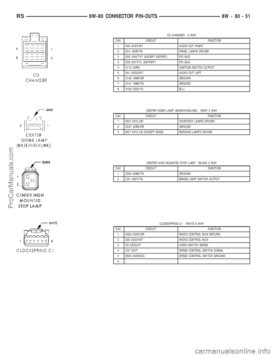
CD CHANGER-8WAY
CAV CIRCUIT FUNCTION
1 X40 24GY/WT AUDIO OUT RIGHT
2 E14 18OR/TN PANEL LAMPS DRIVER
3 D25 20WT/VT (EXCEPT EXPORT) PCI BUS
3 D25 20VT/YL (EXPORT) PCI BUS
4 X112 20RD IGNITION SWITCH OUTPUT
5 X41 20DG/WT AUDIO OUT LEFT
6 Z140 18BK/OR GROUND
7 Z141 18BK/TN GROUND
8 X160 20GY/YL B(+)
CENTER DOME LAMP (BASE/HIGHLINE) - GRAY 3 WAY
CAV CIRCUIT FUNCTION
1 M22 20YL/OR COURTESY LAMPS DRIVER
2 Z327 20BK/OR GROUND
3 M27 20YL/LB (EXCEPT BASE) READING LAMPS DRIVER
CENTER HIGH MOUNTED STOP LAMP - BLACK 2 WAY
CAV CIRCUIT FUNCTION
1 Z350 20BK/TN GROUND
2 L50 18WT/TN BRAKE LAMP SWITCH OUTPUT
CLOCKSPRING C1 - WHITE 6 WAY
CAV CIRCUIT FUNCTION
1 X920 22GY/OR RADIO CONTROL MUX RETURN
2 X20 22GY/WT RADIO CONTROL MUX
3 X3 22DG/VT HORN SWITCH SENSE
4 V37 22VT SPEED CONTROL SWITCH SIGNAL
5 K900 20DB/DG SPEED CONTROL SWITCH GROUND
6- -
RS8W-80 CONNECTOR PIN-OUTS8W-80-51
ProCarManuals.com
Page 1042 of 2177
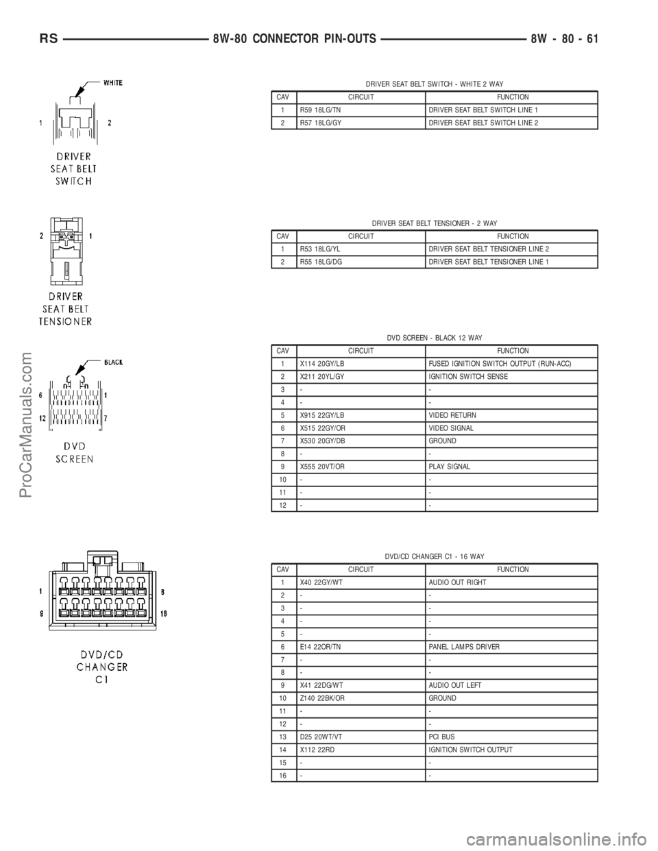
DRIVER SEAT BELT SWITCH - WHITE 2 WAY
CAV CIRCUIT FUNCTION
1 R59 18LG/TN DRIVER SEAT BELT SWITCH LINE 1
2 R57 18LG/GY DRIVER SEAT BELT SWITCH LINE 2
DRIVER SEAT BELT TENSIONER-2WAY
CAV CIRCUIT FUNCTION
1 R53 18LG/YL DRIVER SEAT BELT TENSIONER LINE 2
2 R55 18LG/DG DRIVER SEAT BELT TENSIONER LINE 1
DVD SCREEN - BLACK 12 WAY
CAV CIRCUIT FUNCTION
1 X114 20GY/LB FUSED IGNITION SWITCH OUTPUT (RUN-ACC)
2 X211 20YL/GY IGNITION SWITCH SENSE
3- -
4- -
5 X915 22GY/LB VIDEO RETURN
6 X515 22GY/OR VIDEO SIGNAL
7 X530 20GY/DB GROUND
8- -
9 X555 20VT/OR PLAY SIGNAL
10 - -
11 - -
12 - -
DVD/CD CHANGER C1 - 16 WAY
CAV CIRCUIT FUNCTION
1 X40 22GY/WT AUDIO OUT RIGHT
2- -
3- -
4- -
5- -
6 E14 22OR/TN PANEL LAMPS DRIVER
7- -
8- -
9 X41 22DG/WT AUDIO OUT LEFT
10 Z140 22BK/OR GROUND
11 - -
12 - -
13 D25 20WT/VT PCI BUS
14 X112 22RD IGNITION SWITCH OUTPUT
15 - -
16 - -
RS8W-80 CONNECTOR PIN-OUTS8W-80-61
ProCarManuals.com
Page 1095 of 2177

RADIO C2 (CD CHANGER)-8WAY
CAV CIRCUIT FUNCTION
1 X40 20GY/WT AUDIO OUT RIGHT
2 E14 18OR/TN PANEL LAMPS DRIVER
3 D25 20WT/VT (EXCEPT EXPORT) PCI BUS
3 D25 20VT/YL (EXPORT) PCI BUS
4 X112 20RD IGNITION SWITCH OUTPUT
5 X41 20DG/WT AUDIO OUT LEFT
6 Z140 18BK/OR GROUND
7 Z141 18BK/TN GROUND
8 X160 20GY/YL B(+)
RADIO C2 (DVD/CD CHANGER)-9WAY
CAV CIRCUIT FUNCTION
1 X40 22GY/WT AUDIO OUT RIGHT
2 Z140 22BK/OR GROUND
3- -
4 D25 20WT/VT PCI BUS
5 X112 22RD IGNITION SWITCH OUTPUT
6 X41 22DG/WT AUDIO OUT LEFT
7- -
8- -
9 E14 20OR/TN PANEL LAMPS DRIVER
REAR A/C-HEATER UNIT (3 ZONE MTC) - LT. GREEN 10 WAY
CAV CIRCUIT FUNCTION
1 C53 22LB REAR MODE DOOR DRIVER
2 C154 20LB/OR REAR COMMON DOOR DRIVER
3 C51 12LB/BR FUSED REAR BLOWER MOTOR RELAY OUTPUT
4 C152 16LB/LG REAR BLOWER MOTOR MED
5 C151 18LB/DG REAR BLOWER MOTOR LOW
6 Z135 12BK/LB REAR BLOWER MOTOR HIGH
7 C54 22LB/YL REAR BLEND DOOR DRIVER
8 C154 20LB/OR REAR COMMON DOOR DRIVER
9- -
10 - -
8W - 80 - 114 8W-80 CONNECTOR PIN-OUTSRS
ProCarManuals.com
Page 1419 of 2177
CAUTION: Do not bump or hammer on steering col-
umn or steering column shaft when removing steer-
ing wheel from steering column shaft.
CAUTION: When installing steering wheel puller
bolts in steering wheel, do not thread bolt into
steering wheel more than a half inch. If bolts are
threaded into the steering wheel more than a half
inch they will contact and damage the clockspring.
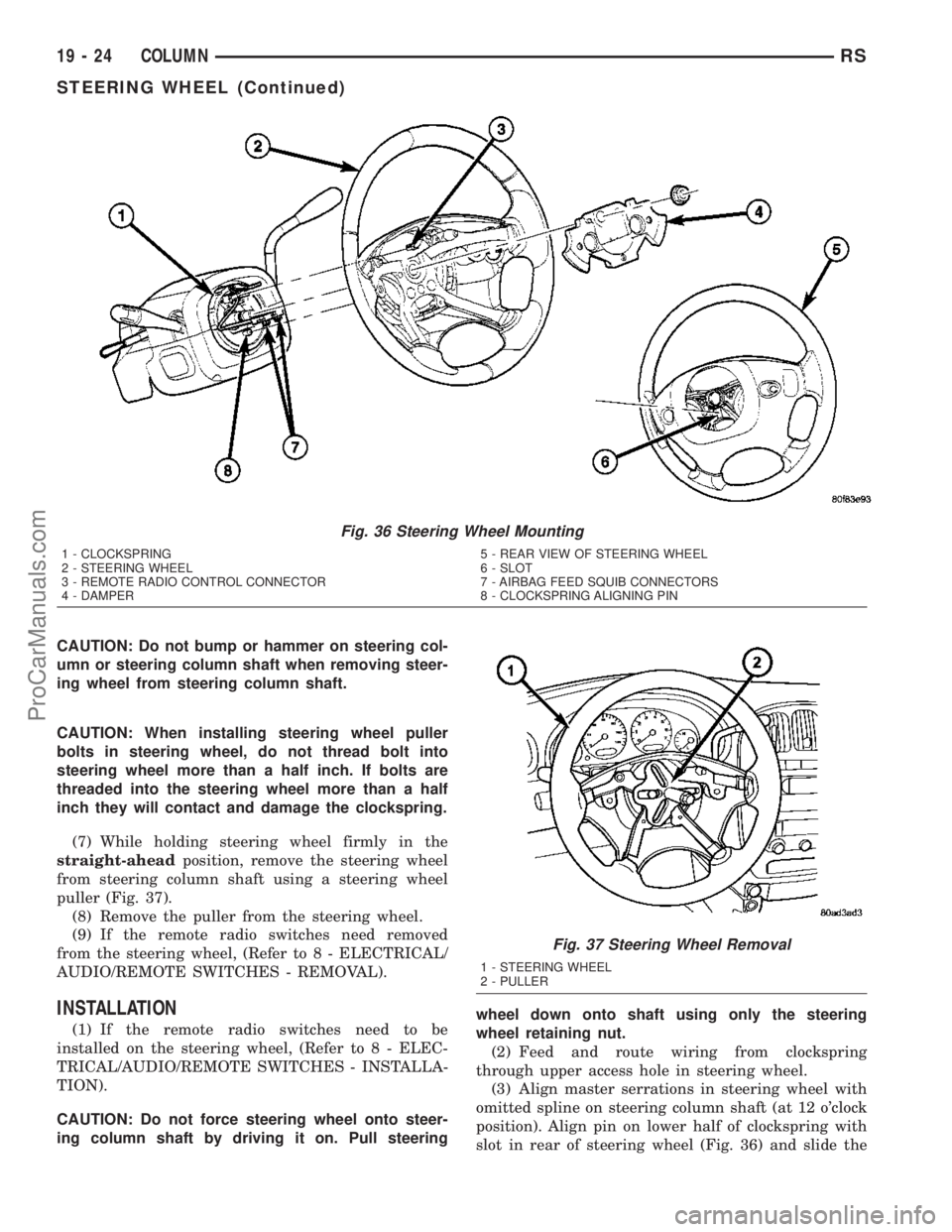
(7) While holding steering wheel firmly in the
straight-aheadposition, remove the steering wheel
from steering column shaft using a steering wheel
puller (Fig. 37).
(8) Remove the puller from the steering wheel.
(9) If the remote radio switches need removed
from the steering wheel, (Refer to 8 - ELECTRICAL/
AUDIO/REMOTE SWITCHES - REMOVAL).
INSTALLATION
(1) If the remote radio switches need to be
installed on the steering wheel, (Refer to 8 - ELEC-
TRICAL/AUDIO/REMOTE SWITCHES - INSTALLA-
TION).
CAUTION: Do not force steering wheel onto steer-
ing column shaft by driving it on. Pull steeringwheel down onto shaft using only the steering
wheel retaining nut.
(2) Feed and route wiring from clockspring
through upper access hole in steering wheel.
(3) Align master serrations in steering wheel with
omitted spline on steering column shaft (at 12 o'clock
position). Align pin on lower half of clockspring with
slot in rear of steering wheel (Fig. 36) and slide the
Fig. 36 Steering Wheel Mounting
1 - CLOCKSPRING
2 - STEERING WHEEL
3 - REMOTE RADIO CONTROL CONNECTOR
4 - DAMPER5 - REAR VIEW OF STEERING WHEEL
6 - SLOT
7 - AIRBAG FEED SQUIB CONNECTORS
8 - CLOCKSPRING ALIGNING PIN
Fig. 37 Steering Wheel Removal
1 - STEERING WHEEL
2 - PULLER
19 - 24 COLUMNRS
STEERING WHEEL (Continued)
ProCarManuals.com
Page 1754 of 2177
(6) Install clips to attach door trim to door frame
around perimeter of panel.
(7) If equipped, install screw to attach door trim to
door panel behind inside latch release handle.
(8) If equipped, connect power switch into wire
connector.
(9) Place power accessary switch in position on
door trim.
(10) Connect wire connector into memory seat/mir-
ror switch and install switch into trim panel.
(11) Install screws to attach accessary switch
panel to door trim.
(12) Install screw cover into switch panel.
(13) If equipped, install window crank.
(14) If equipped, install screws to attach trim
panel to door inside map pocket.
(15) If equipped, install screw to attach door pull
cup to inner door panel.
(16) If equipped, install screws to attach door
assist handle to inner door panel.
(17) Connect wire connector into courtesy lamp.
(18) Install lamp in door trim.
(19) Install switch bezel.
WATERSHIELD
REMOVAL
(1) Remove door trim panel. (Refer to 23 - BODY/
DOOR - FRONT/TRIM PANEL - REMOVAL)
(2) Remove the front door speaker. (Refer to 8 -
ELECTRICAL/AUDIO/SPEAKER - REMOVAL)
(3) Peel watershield away from adhesive around
perimeter of inner door panel.
INSTALLATION
(1) Insure that enough adhesive remains to
securely retain the water dam. Replace as necessary.
(2) Place the shield into position and press
securely to adhesive making sure to properly route
wiring and linkages.
(3) Install the front door speaker. (Refer to 8 -
ELECTRICAL/AUDIO/SPEAKER - INSTALLATION)
(4) Install door trim panel. (Refer to 23 - BODY/
DOOR - FRONT/TRIM PANEL - INSTALLATION)
WINDOW CRANK
REMOVAL
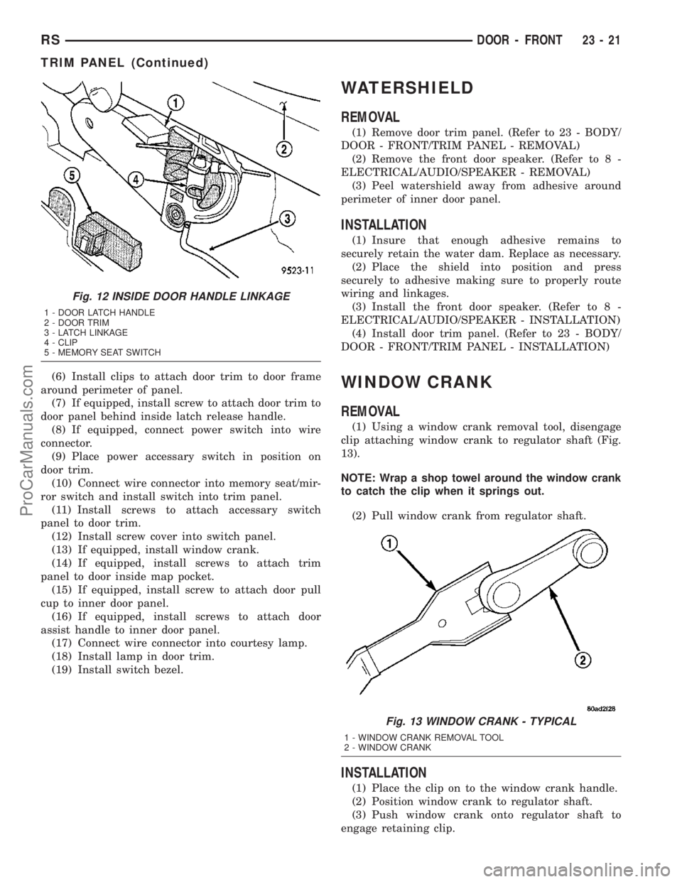
(1) Using a window crank removal tool, disengage
clip attaching window crank to regulator shaft (Fig.
13).
NOTE: Wrap a shop towel around the window crank
to catch the clip when it springs out.
(2) Pull window crank from regulator shaft.
INSTALLATION
(1) Place the clip on to the window crank handle.
(2) Position window crank to regulator shaft.
(3) Push window crank onto regulator shaft to
engage retaining clip.
Fig. 12 INSIDE DOOR HANDLE LINKAGE
1 - DOOR LATCH HANDLE
2 - DOOR TRIM
3 - LATCH LINKAGE
4 - CLIP
5 - MEMORY SEAT SWITCH
Fig. 13 WINDOW CRANK - TYPICAL
1 - WINDOW CRANK REMOVAL TOOL
2 - WINDOW CRANK
RSDOOR - FRONT23-21
TRIM PANEL (Continued)
ProCarManuals.com
Page 1803 of 2177
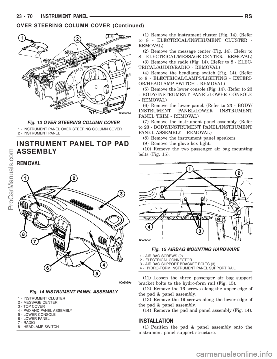
INSTRUMENT PANEL TOP PAD
ASSEMBLY
REMOVAL
(1) Remove the instrument cluster (Fig. 14). (Refer
to 8 - ELECTRICAL/INSTRUMENT CLUSTER -
REMOVAL)
(2) Remove the message center (Fig. 14). (Refer to
8 - ELECTRICAL/MESSAGE CENTER - REMOVAL)
(3) Remove the radio (Fig. 14). (Refer to 8 - ELEC-
TRICAL/AUDIO/RADIO - REMOVAL)
(4) Remove the headlamp switch (Fig. 14). (Refer
to 8 - ELECTRICAL/LAMPS/LIGHTING - EXTERI-
OR/HEADLAMP SWITCH - REMOVAL)
(5) Remove the lower console (Fig. 14). (Refer to 23
- BODY/INSTRUMENT PANEL/LOWER CONSOLE
- REMOVAL)
(6) Remove the lower panel. (Refer to 23 - BODY/
INSTRUMENT PANEL/LOWER INSTRUMENT
PANEL TRIM - REMOVAL)
(7) Remove the instrument panel assembly. (Refer
to 23 - BODY/INSTRUMENT PANEL/INSTRUMENT
PANEL ASSEMBLY - REMOVAL)
(8) Remove the instrument panel speakers.
(9) Remove the glove box light.
(10) Remove the two passenger air bag mounting
bolts (Fig. 15).
(11) Loosen the three passenger air bag support
bracket bolts to the hydro-form rail (Fig. 15).
(12) Remove the 16 screws along the upper edge of
the pad & panel assembly.
(13) Remove the 19 screws along the lower edge of
the pad & panel assembly.
(14) Remove the pad and panel assembly (Fig. 14).
INSTALLATION
(1) Position the pad & panel assembly onto the
instrument panel support structure.
Fig. 13 OVER STEERING COLUMN COVER
1 - INSTRUMENT PANEL OVER STEERING COLUMN COVER
2 - INSTRUMENT PANEL
Fig. 14 INSTRUMENT PANEL ASSEMBLY
1 - INSTRUMENT CLUSTER
2 - MESSAGE CENTER
3 - TOP COVER
4 - PAD AND PANEL ASSEMBLY
5 - LOWER CONSOLE
6 - LOWER PANEL
7 - RADIO
8 - HEADLAMP SWITCH
Fig. 15 AIRBAG MOUNTING HARDWARE
1 - AIR BAG SCREWS (2)
2 - ELECTRICAL CONNECTOR
3 - AIR BAG SUPPORT BRACKET BOLTS (3)
4 - HYDRO-FORM INSTRUMENT PANEL SUPPORT RAIL
23 - 70 INSTRUMENT PANELRS
OVER STEERING COLUMN COVER (Continued)
ProCarManuals.com
Page 1804 of 2177
(2) Install the 19 screws along the lower edge of
the pad & panel assembly.
(3) Install the 16 screws along the upper edge of
the pad & panel assembly.
(4) Install and tighten the two passenger air bag
mounting screws.
(5) Tighten the three passenger air bag support
bracket bolts to the hydro-form tube.
(6) Install the glove box light.
(7) Install the instrument panel speakers.
(8) Install the instrument panel assembly. (Refer
to 23 - BODY/INSTRUMENT PANEL/INSTRUMENT
PANEL ASSEMBLY - INSTALLATION)
(9) Install the lower panel. (Refer to 23 - BODY/
INSTRUMENT PANEL/LOWER INSTRUMENT
PANEL TRIM - INSTALLATION)(10) Install the lower console. (Refer to 23 - BODY/
INSTRUMENT PANEL/LOWER CONSOLE -
INSTALLATION)
(11) Install the headlamp switch. (Refer to 8 -
ELECTRICAL/LAMPS/LIGHTING - EXTERIOR/
HEADLAMP SWITCH - INSTALLATION)
(12) Install the radio. (Refer to 8 - ELECTRICAL/
AUDIO/RADIO - INSTALLATION)
(13) Install the message center. (Refer to 8 -
ELECTRICAL/MESSAGE CENTER - INSTALLA-
TION)
(14) Install the instrument cluster. (Refer to 8 -
ELECTRICAL/INSTRUMENT CLUSTER - INSTAL-
LATION)
RSINSTRUMENT PANEL23-71
INSTRUMENT PANEL TOP PAD ASSEMBLY (Continued)
ProCarManuals.com