Powertrain c3 CHRYSLER VOYAGER 2003 Service Manual
[x] Cancel search | Manufacturer: CHRYSLER, Model Year: 2003, Model line: VOYAGER, Model: CHRYSLER VOYAGER 2003Pages: 2177, PDF Size: 59.81 MB
Page 120 of 2177
PROPELLER SHAFT
TABLE OF CONTENTS
page page
PROPELLER SHAFT
DESCRIPTION.........................21
OPERATION...........................21REMOVAL.............................21
INSTALLATION.........................22
SPECIFICATIONS - PROPELLER SHAFT.....22
PROPELLER SHAFT
DESCRIPTION
WARNING: Due to propeller shaft imbalance con-
cerns, the propeller shaft can only be serviced as
an assembly.
AWD models utilize a ªtwo-pieceº propeller shaft
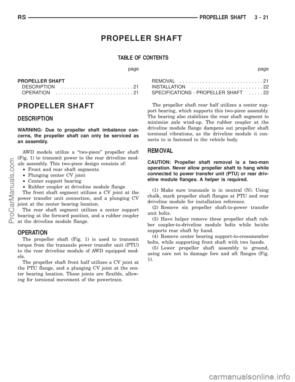
(Fig. 1) to transmit power to the rear driveline mod-
ule assembly. This two-piece design consists of:
²Front and rear shaft segments.
²Plunging center CV joint
²Center support bearing
²Rubber coupler at driveline module flange
The front shaft segment utilizes a CV joint at the
power transfer unit connection, and a plunging CV
joint at the center bearing location.
The rear shaft segment utilizes a center support
bearing at the forward position, and a rubber coupler
at the driveline module flange.
OPERATION
The propeller shaft (Fig. 1) is used to transmit
torque from the transaxle power transfer unit (PTU)
to the rear driveline module of AWD equipped mod-
els.
The propeller shaft front half utilizes a CV joint at
the PTU flange, and a plunging CV joint at the cen-
ter bearing location. These joints are flexible, allow-
ing for torsional movement of the powertrain.The propeller shaft rear half utilizes a center sup-
port bearing, which supports this two-piece assembly.
The bearing also stabilizes the rear shaft segment to
minimize axle wind-up. The rubber coupler at the
driveline module flange dampens out propeller shaft
torsional vibrations, as the driveline module it con-
nects to is fastened to the vehicle body.
REMOVAL
CAUTION: Propeller shaft removal is a two-man
operation. Never allow propeller shaft to hang while
connected to power transfer unit (PTU) or rear driv-
eline module flanges. A helper is required.
(1) Make sure transaxle is in neutral (N). Using
chalk, mark propeller shaft flanges at PTU and rear
driveline module for installation reference.
(2) Remove six propeller shaft-to-power transfer
unit bolts.
(3) Have helper remove three propeller shaft rub-
ber coupler-to-driveline module bolts while he/she
supports rear shaft by hand.
(4) Remove center bearing support-to-crossmember
bolts, while supporting front shaft with two hands.
(5) Lower propeller shaft assembly to ground,
using care not to damage fore and aft flanges (Fig.
1).
RSPROPELLER SHAFT3-21
ProCarManuals.com
Page 282 of 2177
DIAGNOSIS AND TESTING - ENGINE COOLANT
THERMOSTAT
The thermostat is operated by a wax filled cham-
ber (pellet) which is sealed. When heated coolant
reaches a predetermined temperature the wax pellet
expands enough to overcome the closing spring and
water pump pressure, which forces the valve to open.
Coolant leakage into the pellet will cause a thermo-
stat to fail open. Do not attempt to free up a thermo-
stat with a screwdriver.
Thermostat diagnostics is included in powertrain
control module's (PCM) programing for on-board
diagnosis. The malfunction indicator light (MIL) will
illuminate and a diagnostic trouble code (DTC) will
be set when an ªopen too soonº condition occurs. Do
not change a thermostat for lack of heater perfor-
mance or temperature gauge position, unless a DTC
is present. For other probable causes, (Refer to 7 -
COOLING/ENGINE - DIAGNOSIS AND TESTING).
Thermostat failing shut is the normal long term
mode of failure, and normally, only on high mileage
vehicles. The temperature gauge will indicate this
(Refer to 7 - COOLING/ENGINE - DIAGNOSIS AND
TESTING).
ENGINE COOLANT
THERMOSTAT - 2.4L
REMOVAL
(1) Drain cooling system below the thermostat
level. (Refer to 7 - COOLING - STANDARD PROCE-
DURE)
(2) Remove radiator upper hose from the coolant
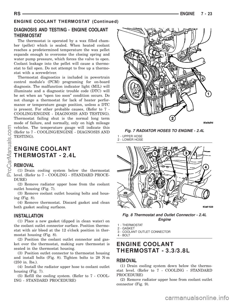
outlet housing (Fig. 7).
(3) Remove coolant outlet housing bolts and hous-
ing (Fig. 8).
(4) Remove thermostat. Discard gasket and clean
both gasket sealing surfaces.
INSTALLATION
(1) Place a new gasket (dipped in clean water) on
the coolant outlet connector surface. Position thermo-
stat with air bleed at the 12 o'clock position in ther-
mostat housing (Fig. 8).
(2) Position the coolant outlet connector and gas-
ket over the thermostat, making sure thermostat is
seated in the thermostat housing.
(3) Position outlet connector to thermostat housing
and install bolts (Fig. 8). Tighten bolts to 28 N´m
(250 in. lbs.).
(4) Install the radiator upper hose to coolant outlet
housing (Fig. 7).
(5) Refill the cooling system. (Refer to 7 - COOL-
ING - STANDARD PROCEDURE)
ENGINE COOLANT
THERMOSTAT - 3.3/3.8L
REMOVAL
(1) Drain cooling system down below the thermo-
stat level. (Refer to 7 - COOLING - STANDARD
PROCEDURE)
(2) Remove radiator upper hose from coolant outlet
connector (Fig. 9).
Fig. 7 RADIATOR HOSES TO ENGINE - 2.4L
1 - UPPER HOSE
2 - LOWER HOSE
Fig. 8 Thermostat and Outlet Connector - 2.4L
Engine
1 - THERMOSTAT
2 - GASKET
3 - COOLANT OUTLET CONNECTOR
4 - BOLT
RSENGINE7-23
ENGINE COOLANT THERMOSTAT (Continued)
ProCarManuals.com
Page 288 of 2177
OPERATION
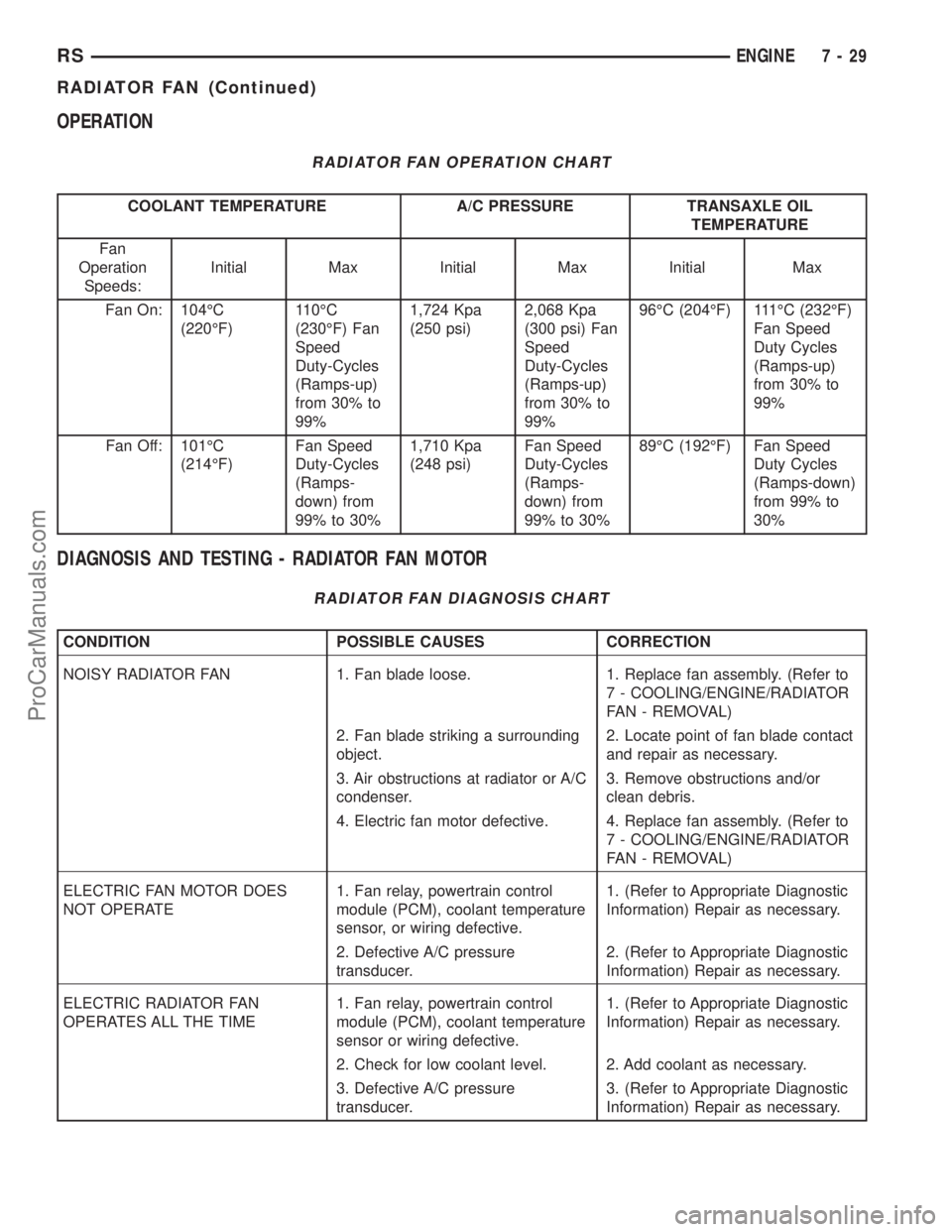
RADIATOR FAN OPERATION CHART
COOLANT TEMPERATURE A/C PRESSURE TRANSAXLE OIL
TEMPERATURE
Fan
Operation
Speeds:Initial Max Initial Max Initial Max
Fan On: 104ÉC
(220ÉF)110ÉC
(230ÉF) Fan
Speed
Duty-Cycles
(Ramps-up)
from 30% to
99%1,724 Kpa
(250 psi)2,068 Kpa
(300 psi) Fan
Speed
Duty-Cycles
(Ramps-up)
from 30% to
99%96ÉC (204ÉF) 111ÉC (232ÉF)
Fan Speed
Duty Cycles
(Ramps-up)
from 30% to
99%
Fan Off: 101ÉC
(214ÉF)Fan Speed
Duty-Cycles
(Ramps-
down) from
99% to 30%1,710 Kpa
(248 psi)Fan Speed
Duty-Cycles
(Ramps-
down) from
99% to 30%89ÉC (192ÉF) Fan Speed
Duty Cycles
(Ramps-down)
from 99% to
30%
DIAGNOSIS AND TESTING - RADIATOR FAN MOTOR
RADIATOR FAN DIAGNOSIS CHART
CONDITION POSSIBLE CAUSES CORRECTION
NOISY RADIATOR FAN 1. Fan blade loose. 1. Replace fan assembly. (Refer to
7 - COOLING/ENGINE/RADIATOR
FAN - REMOVAL)
2. Fan blade striking a surrounding
object.2. Locate point of fan blade contact
and repair as necessary.
3. Air obstructions at radiator or A/C
condenser.3. Remove obstructions and/or
clean debris.
4. Electric fan motor defective. 4. Replace fan assembly. (Refer to
7 - COOLING/ENGINE/RADIATOR
FAN - REMOVAL)
ELECTRIC FAN MOTOR DOES
NOT OPERATE1. Fan relay, powertrain control
module (PCM), coolant temperature
sensor, or wiring defective.1. (Refer to Appropriate Diagnostic
Information) Repair as necessary.
2. Defective A/C pressure
transducer.2. (Refer to Appropriate Diagnostic
Information) Repair as necessary.
ELECTRIC RADIATOR FAN
OPERATES ALL THE TIME1. Fan relay, powertrain control
module (PCM), coolant temperature
sensor or wiring defective.1. (Refer to Appropriate Diagnostic
Information) Repair as necessary.
2. Check for low coolant level. 2. Add coolant as necessary.
3. Defective A/C pressure
transducer.3. (Refer to Appropriate Diagnostic
Information) Repair as necessary.
RSENGINE7-29
RADIATOR FAN (Continued)
ProCarManuals.com
Page 289 of 2177
REMOVAL
There are no repairs to be made to the fan or
shroud assembly. If the fan is warped, cracked, or
otherwise damaged, it must be replaced as an assem-
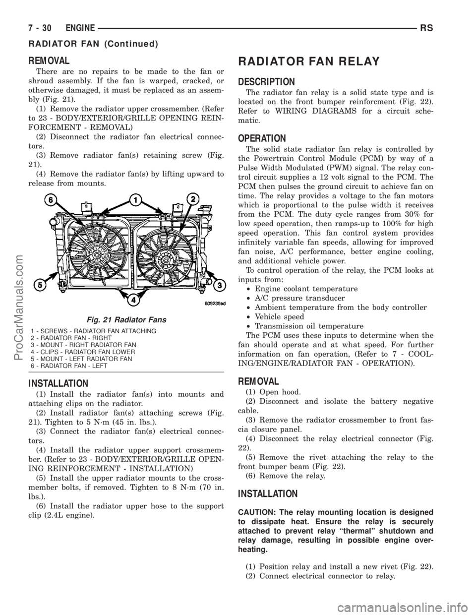
bly (Fig. 21).
(1) Remove the radiator upper crossmember. (Refer
to 23 - BODY/EXTERIOR/GRILLE OPENING REIN-
FORCEMENT - REMOVAL)
(2) Disconnect the radiator fan electrical connec-
tors.
(3) Remove radiator fan(s) retaining screw (Fig.
21).
(4) Remove the radiator fan(s) by lifting upward to
release from mounts.
INSTALLATION
(1) Install the radiator fan(s) into mounts and
attaching clips on the radiator.
(2) Install radiator fan(s) attaching screws (Fig.
21). Tighten to 5 N´m (45 in. lbs.).
(3) Connect the radiator fan(s) electrical connec-
tors.
(4) Install the radiator upper support crossmem-
ber. (Refer to 23 - BODY/EXTERIOR/GRILLE OPEN-
ING REINFORCEMENT - INSTALLATION)
(5) Install the upper radiator mounts to the cross-
member bolts, if removed. Tighten to 8 N´m (70 in.
lbs.).
(6) Install the radiator upper hose to the support
clip (2.4L engine).
RADIATOR FAN RELAY
DESCRIPTION
The radiator fan relay is a solid state type and is
located on the front bumper reinforcment (Fig. 22).
Refer to WIRING DIAGRAMS for a circuit sche-
matic.
OPERATION
The solid state radiator fan relay is controlled by
the Powertrain Control Module (PCM) by way of a
Pulse Width Modulated (PWM) signal. The relay con-
trol circuit supplies a 12 volt signal to the PCM. The
PCM then pulses the ground circuit to achieve fan on
time. The relay provides a voltage to the fan motors
which is proportional to the pulse width it receives
from the PCM. The duty cycle ranges from 30% for
low speed operation, then ramps-up to 100% for high
speed operation. This fan control system provides
infinitely variable fan speeds, allowing for improved
fan noise, A/C performance, better engine cooling,
and additional vehicle power.
To control operation of the relay, the PCM looks at
inputs from:
²Engine coolant temperature
²A/C pressure transducer
²Ambient temperature from the body controller
²Vehicle speed
²Transmission oil temperature
The PCM uses these inputs to determine when the
fan should operate and at what speed. For further
information on fan operation, (Refer to 7 - COOL-
ING/ENGINE/RADIATOR FAN - OPERATION).
REMOVAL
(1) Open hood.
(2) Disconnect and isolate the battery negative
cable.
(3) Remove the radiator crossmember to front fas-
cia closure panel.
(4) Disconnect the relay electrical connector (Fig.
22).
(5) Remove the rivet attaching the relay to the
front bumper beam (Fig. 22).
(6) Remove the relay.
INSTALLATION
CAUTION: The relay mounting location is designed
to dissipate heat. Ensure the relay is securely
attached to prevent relay ªthermalº shutdown and
relay damage, resulting in possible engine over-
heating.
(1) Position relay and install a new rivet (Fig. 22).
(2) Connect electrical connector to relay.
Fig. 21 Radiator Fans
1 - SCREWS - RADIATOR FAN ATTACHING
2 - RADIATOR FAN - RIGHT
3 - MOUNT - RIGHT RADIATOR FAN
4 - CLIPS - RADIATOR FAN LOWER
5 - MOUNT - LEFT RADIATOR FAN
6 - RADIATOR FAN - LEFT
7 - 30 ENGINERS
RADIATOR FAN (Continued)
ProCarManuals.com
Page 316 of 2177
ELECTRONIC CONTROL MODULES
TABLE OF CONTENTS
page page
ELECTRONIC CONTROL MODULES
STANDARD PROCEDURE - PCM/SKIM
PROGRAMMING.......................2
BODY CONTROL MODULE
DESCRIPTION..........................3
OPERATION............................3
REMOVAL.............................4
INSTALLATION..........................5
CONTROLLER ANTILOCK BRAKE
DESCRIPTION..........................5
OPERATION............................5
REMOVAL.............................6
INSTALLATION..........................6
DATA LINK CONNECTOR
DESCRIPTION..........................6
OPERATION............................7
FRONT CONTROL MODULE
DESCRIPTION..........................7
OPERATION............................7
DIAGNOSIS AND TESTING - FRONT
CONTROL MODULE....................7
REMOVAL.............................8
INSTALLATION..........................8
HEATED SEAT MODULE
DESCRIPTION..........................8
OPERATION............................9
DIAGNOSIS AND TESTING - HEATED SEAT
MODULE.............................9
REMOVAL.............................9
INSTALLATION.........................10
MEMORY SEAT/MIRROR MODULE
DESCRIPTION.........................10
OPERATION...........................10
DIAGNOSIS AND TESTING - MEMORY
SEAT/MIRROR MODULE................10
REMOVAL.............................10
INSTALLATION.........................10
POWER LIFTGATE CONTROL MODULE
DESCRIPTION.........................10
OPERATION...........................11
REMOVAL.............................11
INSTALLATION.........................11
POWERTRAIN CONTROL MODULE
DESCRIPTION
DESCRIPTION........................11OPERATION - SENSOR RETURN - PCM
INPUT..............................15
OPERATION - DATA BUS COMMUNICATION
RECEIVE - PCM INPUT.................15
OPERATION - IGNITION SENSE - PCM
INPUT..............................15
OPERATION - PCM GROUND............15
OPERATION
OPERATION - 8-VOLT SUPPLY - PCM
OUTPUT - SBEC CONTROLLER..........15
OPERATION - 5 VOLT SUPPLY - PCM
OUTPUT............................15
STANDARD PROCEDURE
STANDARD PROCEDURE - OBTAINING
DIAGNOSTIC TROUBLE CODES..........15
STANDARD PROCEDURE - PINION
FACTOR SETTING.....................15
STANDARD PROCEDURE - QUICK LEARN
PROCEDURE........................16
REMOVAL
REMOVAL - SBEC CONTROLLER.........16
REMOVAL - NGC CONTROLLER..........17
INSTALLATION
INSTALLATION - SBEC CONTROLLER.....17
INSTALLATION.......................17
SENTRY KEY IMMOBILIZER MODULE
DESCRIPTION.........................18
OPERATION...........................18
REMOVAL.............................18
INSTALLATION.........................19
SLIDING DOOR CONTROL MODULE
DESCRIPTION.........................19
OPERATION...........................19
REMOVAL.............................19
INSTALLATION.........................20
TRANSMISSION CONTROL MODULE
DESCRIPTION.........................20
OPERATION...........................20
STANDARD PROCEDURE
STANDARD PROCEDURE - PINION
FACTOR SETTING.....................23
STANDARD PROCEDURE - QUICK LEARN
PROCEDURE........................23
REMOVAL.............................23
INSTALLATION.........................24
RSELECTRONIC CONTROL MODULES8E-1
ProCarManuals.com
Page 318 of 2177
(5) Obtain ignition keys to be programmed from
customer (8 keys maximum).
(6) Using the DRB III, erase all ignition keys by
selecting MISCELLANEOUS and ERASE ALL CUR-
RENT IGN. KEYS.
(7) Program all ignition keys.
Learned Key In Ignition - Ignition key transponder
ID is currently programmed in SKIM memory.
BODY CONTROL MODULE
DESCRIPTION
The Body Control Module (BCM) is located in the
passenger compartment, attached to the bulkhead
underneath the left side of the instrument panel.
The BCM utilizes integrated circuitry and informa-
tion carried on the Programmable Communications
Interface (PCI) data bus network along with many
hard wired inputs to monitor many sensor and
switch inputs throughout the vehicle. In response to
those inputs, the internal circuitry and programming
of the BCM allow it to control and integrate many
electronic functions and features of the vehicle
through both hard wired outputs and the transmis-
sion of electronic message outputs to other electronic
modules in the vehicle over the PCI data bus.
OPERATION
The Body Control Module (BCM) supplies vehicle
occupants with visual and audible information and
controls various vehicle functions. To provide and
receive information, the BCM is interfaced to the
vehicle's serial bus communications network, referred
to as the Programmable Communications Interface
(PCI) bus.
This network consists of the;
²Powertrain Control Module (PCM)
²Transmission Control Module (TCM)
²Mechanical Instrument Cluster (MIC)
²Occupant Restraint Controller (ORC)
²Compass/Mini-Trip Computer (CMTC)
²Electronic Vehicle Information Center (EVIC)
²Controller Antilock Brake (CAB)²HVAC Control Module
²Sliding Door Control Modules (driver and pas-
senger side doors)
²Power Liftgate Module (PLG)
²Audio system equipped with RAZ, RBU, RBK,
and RBB radios.
²Side Impact Airbag Control Module (SIACM)
²Memory Seat Module (MSM)
²Sentry Key Immobilizer Module (SKIM)
The BCM is operational when battery power is
supplied to the module.
The BCM provides the following features:
²Power Door Locks
²Automatic Door Locks
²Battery Protection - The BCM will automatically
turn off all exterior lamps after 3 minutes, and all
interior lamps after 15 minutes after the ignition is
turned off, if they are not turned off by the driver.
²Chime Control
²Compass/Mini-Trip support.
²Interior Lighting (Courtesy/Reading Lamps)
²BCM Diagnostic Reporting
²Electronic Liftgate Release (with Power Door
Locks)
²Exterior Lighting
²Headlamp Time Delay (with/without Automatic
Headlamps)
²Illuminated Entry
²Fade to Off Interior Lamps - This feature dims
the interior lighting (courtesy lamps) gradually if the
BCM does not receive any new inputs that would
cause the interior lamps to remain on.
²Pulse Width Modulated Instrument Panel Dim-
ming
²Door Lock Inhibit - This feature disables the
door lock functions if the key is in the ignition and
either front door is ajar. Pressing the Remote Keyless
Entry (RKE) lock/unlock button under these condi-
tions result in normal lock/unlock activation.
The BCM has the ability to LEARN additional fea-
tures in the vehicle, provided the appropriate switch
input and PCI data bus messages are received. Refer
to the LEARNED FEATURES table.
RSELECTRONIC CONTROL MODULES8E-3
ELECTRONIC CONTROL MODULES (Continued)
ProCarManuals.com
Page 322 of 2177
OPERATION
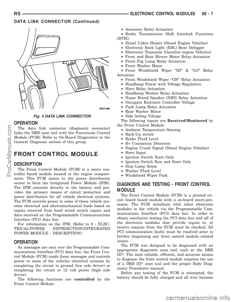
The data link connector (diagnostic connector)
links the DRB scan tool with the Powertrain Control
Module (PCM). Refer to On-Board Diagnostics in the
General Diagnosis section of this group.
FRONT CONTROL MODULE
DESCRIPTION
The Front Control Module (FCM) is a micro con-
troller based module located in the engine compart-
ment. This FCM mates to the power distribution
center to form the Integrated Power Module (IPM).
The IPM connects directly to the battery and pro-
vides the primary means of circuit protection and
power distribution for all vehicle electrical systems.
The FCM controls power to some of these vehicle sys-
tems electrical and electromechanical loads based on
inputs received from hard wired switch inputs and
data received on the Programmable Communications
Interface (PCI) data bus.
For information on the IPM, (Refer to 8 - ELEC-
TRICAL/POWER DISTRIBUTION/INTEGRATED
POWER MODULE - DESCRIPTION)
OPERATION
As messages are sent over the Programmable Com-
munications Interface (PCI) data bus, the Front Con-
trol Module (FCM) reads these messages and controls
power to some of the vehicles electrical systems by
completing the circuit to ground (low side driver) or
completing the circuit to 12 volt power (high side
driver).
The following functions arecontrolledby the
Front Control Module:²Accessory Relay Actuation
²Brake Transmission Shift Interlock Functions
(BTSI)
²Diesel Cabin Heater (Diesel Engine Vehicles)
²Electronic Back Light (EBL) Rear Defogger
²Electronic Transaxle (Gasoline engine Vehicles)
²Front and Rear Blower Motor Relay Actuation
²Front Fog Lamp Relay Actuation
²Front Washer Motor
²Front Windshield Wiper ªHIº & ªLOº Relay
Actuation
²Front Windshield Wiper ªONº Relay Actuation
²Headlamp Power with Voltage Regulation
²Horn Relay Actuation
²Headlamp Washer Relay Actuation
²Name Brand Speaker (NBS) Relay Actuation
²Occupant Restraint Controller Voltage
²Park Lamp Relay Actuation
²Rear Washer Motor
²Side Airbag Voltage
The following inputs areReceived/Monitoredby
the Front Control Module:
²Ambient Temperature Sensing
²Back-Up switch
²Brake Fluid Level
²B+ Connection Detection
²Engine Crank Signal (Diesel Engine Vehicles)
²Horn Input
²Ignition Switch Start Only
²Ignition Switch Run and Start Only
²Stop Lamp Sense
²Washer Fluid Level
²Windshield Wiper Park
DIAGNOSIS AND TESTING - FRONT CONTROL
MODULE
The Front Control Module (FCM) is a printed cir-
cuit board based module with a on-board micro-pro-
cessor. The FCM interfaces with other electronic
modules in the vehicle via the Programmable Com-
munications Interface (PCI) data bus. In order to
obtain conclusive testing the PCI data bus and all of
the electronic modules that provide inputs to, or
receive outputs from the FCM must be checked. All
PCI communication faults must be resolved prior to
further diagnosing any front control module related
issues.
The FCM was designed to be diagnosed with an
appropriate diagnostic scan tool, such as the DRB
IIIt. The most reliable, efficient, and accurate means
to diagnose the front control module requires the use
of a DRB IIItscan tool and the proper Body Diag-
nostic Procedures manual.
Before any testing of the FCM is attempted, the
battery should be fully charged and all wire harness
Fig. 4 DATA LINK CONNECTOR
RSELECTRONIC CONTROL MODULES8E-7
DATA LINK CONNECTOR (Continued)
ProCarManuals.com
Page 325 of 2177
INSTALLATION
(1) Connect the module wire harness connectors.
(2) Snap the module on the seat cushion pan.
(3) Install the appropriate front seat in the vehicle
(Refer to 23 - BODY/SEATS/SEAT - INSTALLA-
TION).
(4) Connect and isolate the negative battery cable.
MEMORY SEAT/MIRROR
MODULE
DESCRIPTION
Vehicles equipped with the memory seat/mirror
option, utilize a memory module located under the
drivers front seat. This module is basically wired in-
line between the power seat switch and the power
seat track/adjuster motors, or in-line between the
power mirror switch and the power side view mir-
ror(s) motor(s). The MSMM contains a central pro-
cessing unit that communicates with other modules
on the Programmable Communications Interface
(PCI) data bus network.
The Memory Seat/Mirror Module (MSMM) receives
hard wired inputs from the driver power seat switch
and the potentiometers on each of the driver side
power seat track motors, or from the power mirror
switch and the potentiometers on the side view mir-
ror. The MSMM receives messages over the PCI data
bus from the Body Control Module (BCM) (memory
switch status), the Powertrain Control Module (PCM)
(vehicle speed status). The MSMM will prevent the
seat memory recall function from being initiated if
the driver side seat belt is buckled, if the transmis-
sion gear selector lever is not in the Park or Neutral
positions, or if the vehicle is moving.
For diagnosis of the MSMM or the PCI data bus, a
DRB IIItscan tool and the proper Diagnostic Proce-
dures manual are recommended. The MSMM cannot
be repaired and, if faulty or damaged, it must be
replaced. Refer toMemory Systemin the Power
Seat or Power Mirror section of this manual for more
information on the memory system option.
OPERATION
When memory system operation is requested
(depressing of the memory switch), a resistor multi-
plexed signal is sent from the memory switch to the
body control module (BCM). The body control module
will then send the appropriate signals out to the
memory/mirror seat module, the memory/mirror seat
module then applies the voltage supply to the power
seat track or side-view mirror if the proper require-
ments are met. The vehicle speed must equal zero
and the transmission must be in park or neutral in
order for the memory system to function.
DIAGNOSIS AND TESTING - MEMORY
SEAT/MIRROR MODULE
Visually inspect the related wiring harness connec-
tors. Look for broken, bent, pushed out, or corroded
terminals. If any of the above conditions are present,
repair as necessary. If not, use a DRB IIItscan tool
and the proper Diagnostic Procedures Manual to test
the memory/mirror seat module. For complete circuit
diagrams, refer toWiring Diagrams.
REMOVAL
(1) Disconnect and isolate the battery negative
cable.
(2) Remove the driver side front bucket seat
retaining nuts from under the vehicle (Refer to 23 -
BODY/SEATS/SEAT - REMOVAL).
(3) Lift the drivers seat up and out of the mount-
ing holes in the floor pan and lay the seat rearward
to access the module located under the seat. It is not
necessary to disconnect the seat electrical, just use
care not to damage the wiring by over-extending.
(4) Disconnect the memory/mirror seat module
electrical connectors. Depress the retaining tab and
pull straight apart.
(5) Remove the module retaining bolts and remove
the module from the bracket.
INSTALLATION
(1) Position and install the module retaining bolts.
(2) Connect the memory/mirror seat module elec-
trical connectors.
(3) Position the drivers seat in the mounting holes
in the floor pan.
(4) Install the driver side front bucket seat retain-
ing nuts from under the vehicle (Refer to 23 - BODY/
SEATS/SEAT - INSTALLATION).
(5) Connect the battery negative cable.
POWER LIFTGATE CONTROL
MODULE
DESCRIPTION
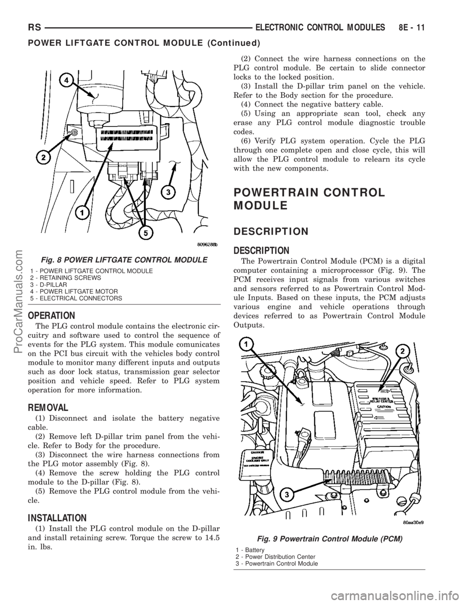
Vehicles equipped with a power liftgate (PLG) uti-
lize a PLG control module. This module is located on
the vehicles left side D-pillar just below the motor
assembly (Fig. 8) and contains a microprocessor,
which is used to communicate to the vehicles body
control module. The PLG control module receives and
monitors logic inputs from all the PLG system
switches except for the outside handle switch. This
module also contains the software technology to
detect liftgate obstructions and stop and/or reverse
the door accordingly.
8E - 10 ELECTRONIC CONTROL MODULESRS
HEATED SEAT MODULE (Continued)
ProCarManuals.com
Page 326 of 2177
OPERATION
The PLG control module contains the electronic cir-
cuitry and software used to control the sequence of
events for the PLG system. This module comunicates
on the PCI bus circuit with the vehicles body control
module to monitor many different inputs and outputs
such as door lock status, transmission gear selector
position and vehicle speed. Refer to PLG system
operation for more information.
REMOVAL
(1) Disconnect and isolate the battery negative
cable.
(2) Remove left D-pillar trim panel from the vehi-
cle. Refer to Body for the procedure.
(3) Disconnect the wire harness connections from
the PLG motor assembly (Fig. 8).
(4) Remove the screw holding the PLG control
module to the D-pillar (Fig. 8).
(5) Remove the PLG control module from the vehi-
cle.
INSTALLATION
(1) Install the PLG control module on the D-pillar
and install retaining screw. Torque the screw to 14.5
in. lbs.(2) Connect the wire harness connections on the
PLG control module. Be certain to slide connector
locks to the locked position.
(3) Install the D-pillar trim panel on the vehicle.
Refer to the Body section for the procedure.
(4) Connect the negative battery cable.
(5) Using an appropriate scan tool, check any
erase any PLG control module diagnostic trouble
codes.
(6) Verify PLG system operation. Cycle the PLG
through one complete open and close cycle, this will
allow the PLG control module to relearn its cycle
with the new components.
POWERTRAIN CONTROL
MODULE
DESCRIPTION
DESCRIPTION
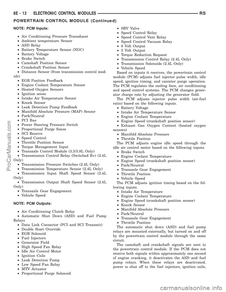
The Powertrain Control Module (PCM) is a digital
computer containing a microprocessor (Fig. 9). The
PCM receives input signals from various switches
and sensors referred to as Powertrain Control Mod-
ule Inputs. Based on these inputs, the PCM adjusts
various engine and vehicle operations through
devices referred to as Powertrain Control Module
Outputs.Fig. 8 POWER LIFTGATE CONTROL MODULE
1 - POWER LIFTGATE CONTROL MODULE
2 - RETAINING SCREWS
3 - D-PILLAR
4 - POWER LIFTGATE MOTOR
5 - ELECTRICAL CONNECTORS
Fig. 9 Powertrain Control Module (PCM)
1 - Battery
2 - Power Distribution Center
3 - Powertrain Control Module
RSELECTRONIC CONTROL MODULES8E-11
POWER LIFTGATE CONTROL MODULE (Continued)
ProCarManuals.com
Page 327 of 2177
NOTE: PCM Inputs:
²Air Conditioning Pressure Transducer
²Ambient temperature Sensor
²ASD Relay
²Battery Temperature Sensor (NGC)
²Battery Voltage
²Brake Switch
²Camshaft Position Sensor
²Crankshaft Position Sensor
²Distance Sensor (from transmission control mod-
ule)
²EGR Position Feedback
²Engine Coolant Temperature Sensor
²Heated Oxygen Sensors
²Ignition sense
²Intake Air Temperature Sensor
²Knock Sensor
²Leak Detection Pump Feedback
²Manifold Absolute Pressure (MAP) Sensor
²Park/Neutral
²PCI Bus
²Power Steering Pressure Switch
²Proportional Purge Sense
²SCI Receive
²Speed Control
²Throttle Position Sensor
²Torque Management Input
²Transaxle Control Module (3.3/3.8L Only)
²Transmission Control Relay (Switched B+) (2.4L
Only)
²Transmission Pressure Switches (2.4L Only)
²Transmission Temperature Sensor (2.4L Only)
²Transmission Input Shaft Speed Sensor (2.4L
Only)
²Transmission Output Shaft Speed Sensor (2.4L
Only)
²Transaxle Gear Engagement
²Vehicle Speed
NOTE: PCM Outputs:
²Air Conditioning Clutch Relay
²Automatic Shut Down (ASD) and Fuel Pump
Relays
²Data Link Connector (PCI and SCI Transmit)
²Double Start Override
²EGR Solenoid
²Fuel Injectors
²Generator Field
²High Speed Fan Relay
²Idle Air Control Motor
²Ignition Coils
²Leak Detection Pump
²Low Speed Fan Relay
²MTV Actuator
²Proportional Purge Solenoid²SRV Valve
²Speed Control Relay
²Speed Control Vent Relay
²Speed Control Vacuum Relay
²8 Volt Output
²5 Volt Output
²Torque Reduction Request
²Transmission Control Relay (2.4L Only)
²Transmission Solenoids (2.4L Only)
²Vehicle Speed
Based on inputs it receives, the powertrain control
module (PCM) adjusts fuel injector pulse width, idle
speed, ignition timing, and canister purge operation.
The PCM regulates the cooling fans, air conditioning
and speed control systems. The PCM changes gener-
ator charge rate by adjusting the generator field.
The PCM adjusts injector pulse width (air-fuel
ratio) based on the following inputs.
²Battery Voltage
²Intake Air Temperature Sensor
²Engine Coolant Temperature
²Engine Speed (crankshaft position sensor)
²Exhaust Gas Oxygen Content (heated oxygen
sensors)
²Manifold Absolute Pressure
²Throttle Position
The PCM adjusts engine idle speed through the
idle air control motor based on the following inputs.
²Brake Switch
²Engine Coolant Temperature
²Engine Speed (crankshaft position sensor)
²Park/Neutral
²Transaxle Gear Engagement
²Throttle Position
²Vehicle Speed
The PCM adjusts ignition timing based on the fol-
lowing inputs.
²Intake Air Temperature
²Engine Coolant Temperature
²Engine Speed (crankshaft position sensor)
²Knock Sensor
²Manifold Absolute Pressure
²Park/Neutral
²Transaxle Gear Engagement
²Throttle Position
The automatic shut down (ASD) and fuel pump
relays are mounted externally, but turned on and off
by the powertrain control module through the same
circuit.
The camshaft and crankshaft signals are sent to
the powertrain control module. If the PCM does not
receive both signals within approximately one second
of engine cranking, it deactivates the ASD and fuel
pump relays. When these relays are deactivated,
power is shut off to the fuel injectors, ignition coils,
8E - 12 ELECTRONIC CONTROL MODULESRS
POWERTRAIN CONTROL MODULE (Continued)
ProCarManuals.com