seat adjustment CHRYSLER VOYAGER 2003 Service Manual
[x] Cancel search | Manufacturer: CHRYSLER, Model Year: 2003, Model line: VOYAGER, Model: CHRYSLER VOYAGER 2003Pages: 2177, PDF Size: 59.81 MB
Page 76 of 2177

NOTE: If equipped with antilock brakes, make sure
wheel speed sensor stays clean and dry as it is
installed into the hub and bearing cap.
(4) If the vehicle is equipped with antilock brakes,
perform the following:
(a) If metal sensor retaining clip is not in the
neutral installed position on hub and bearing cap,
install from the bottom, if necessary, and push clip
upward until it snaps into position.
(b) Install wheel speed sensor head into rear of
hub and bearing aligning index tab with the notch
in the top of the mounting hole. Push the sensor in
until it snaps into place on the metal retaining
clip.
(c) Install secondary (yellow) retaining clip over
wheel speed sensor head and engage the tabs on
each side (Fig. 8).
(5) Install brake drum or disc brake rotor and
brake caliper. (Refer to 5 - BRAKES/HYDRAULIC/
MECHANICAL/DRUM - INSTALLATION)(Refer to 5
- BRAKES/HYDRAULIC/MECHANICAL/ROTOR -
INSTALLATION)
(6) Install wheel and tire (Refer to 22 - TIRES/
WHEELS - INSTALLATION). Tighten the wheel
nuts in the proper sequence to a torque of 135 N´m
(100 ft. lbs.).
(7) Adjust the rear brakes as necessary. (Refer to 5
- BRAKES/HYDRAULIC/MECHANICAL/BRAKE
PADS/SHOES - ADJUSTMENTS)
(8) Lower vehicle.
(9) Road test vehicle to ensure proper operation of
brakes.
ALL-WHEEL-DRIVE VEHICLES
(1) Install hub/bearing on end of axle. (Fig. 12).
(2) Install the hub/bearing mounting bolts. In a
progressive crisscross pattern, tighten the 4 hub/
bearing mounting bolts (Fig. 13) until the disc brake
caliper adapter and hub/bearing are squarely seated
against the axle. Then tighten the hub/bearing
mounting bolts to a torque of 129 N´m (95 ft. lbs.).
(3) Install driveshaft in hub/bearing and on output
shaft of rear drive line module. Driveshaft is
installed by first sliding the outer joint of the drive-
shaft into the hub/bearing and then compressing the
Fig. 11 Hub/Bearing Removal From Caliper Adapter
1 - SPECIAL TOOL 8214-1
2 - PARK BRAKE CABLE
3 - DISC BRAKE CALIPER ADAPTER
4 - HUB/BEARING
Fig. 12 Hub/Bearing Removal And Installation
1 - PARK BRAKE BRAKE SHOE
2 - HUB/BEARING
3 - PARK BRAKE BRAKE SHOE
Fig. 13 Hub/Bearing Mounting Bolts
1 - HUB/BEARING
2 - AXLE
3 - MOUNTING BOLTS
4 - CALIPER ADAPTER
RSREAR SUSPENSION2-33
HUB / BEARING (Continued)
ProCarManuals.com
Page 205 of 2177
nects the front parking brake cable to the left rear
and intermediate cable. The intermediate cable is
connected to the right rear cable using a parking
brake cable connector.
On vehicles equipped with rear drum brakes, the
rear service brakes also act as the vehicle's parking
brakes.
Vehicles equipped with rear disc brakes use a
small duo-servo brake assembly mounted to the each
rear disc brake caliper adapter as the parking brake.
The inside of the brake rotor (hat section of drum-in-
hat style brake rotor) is used as the parking brake
drum.
DESCRIPTION - EXPORT
The parking brake system on this vehicle features
a hand-operated parking brake lever. The lever is
located between the two front seats and requires a
special front cable.
OPERATION
The automatic-adjusting feature in the foot oper-
ated parking brake lever continuously applies mini-
mal tension to the parking brake cables when the
parking brake lever is in the released position to
keep them in adjustment at all times. Due to this
feature, the parking brake cables require no periodic
adjustment.
When the parking brake lever is applied, the
cables are pulled, thus applying the brake shoes
(rear drum brakes) or parking brake shoes (rear disc
brakes) at each rear wheel.
The brake shoes are mechanically operated by an
internal lever and strut connected to the rear park-
ing brake cables.
An equalizer bracket is used at the rear end of the
front parking brake cable to distribute tension
equally to each parking brake cable.
STANDARD PROCEDURE
STANDARD PROCEDURE - PARKING BRAKE
AUTOMATIC ADJUSTER TENSION RELEASE
The parking brake lever (pedal) mechanism used
in this vehicle is designed so that the automatic
adjuster is not required to be locked out when servic-
ing the parking brake lever (pedal) or the parking
brake cables.
This parking brake lever (pedal) mechanism is
designed so that the adjuster mechanism will rotate
only half a turn when the tension is released from
the parking brake cable. This eliminates the require-
ment to lock out the automatic adjuster when servic-
ing the parking brake lever (pedal) mechanism and
cables.Use the following procedure to release the tension
from the parking brake cables and the automatic
adjuster in the parking brake lever (pedal) mecha-
nism.
(1) Grasp the exposed section of the front parking
brake cable and pull rearward on it. While holding
the park brake in this position, install a pair of lock-
ing pliers on the front parking brake cable just rear-
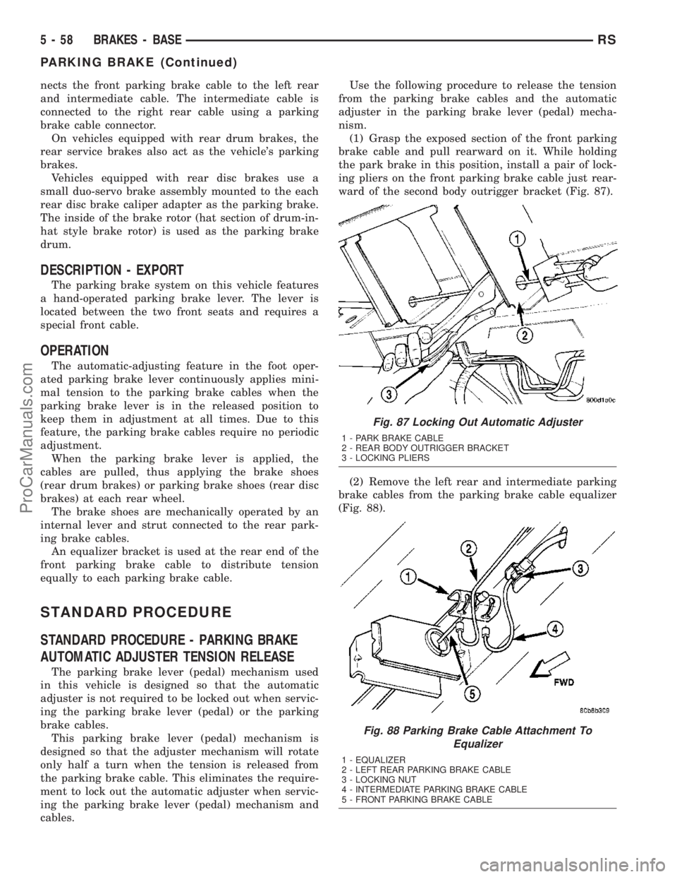
ward of the second body outrigger bracket (Fig. 87).
(2) Remove the left rear and intermediate parking
brake cables from the parking brake cable equalizer
(Fig. 88).
Fig. 87 Locking Out Automatic Adjuster
1 - PARK BRAKE CABLE
2 - REAR BODY OUTRIGGER BRACKET
3 - LOCKING PLIERS
Fig. 88 Parking Brake Cable Attachment To
Equalizer
1 - EQUALIZER
2 - LEFT REAR PARKING BRAKE CABLE
3 - LOCKING NUT
4 - INTERMEDIATE PARKING BRAKE CABLE
5 - FRONT PARKING BRAKE CABLE
5 - 58 BRAKES - BASERS
PARKING BRAKE (Continued)
ProCarManuals.com
Page 211 of 2177
INSTALLATION - PARKING BRAKE CABLE
(LEFT REAR)
(1) Install the rear parking brake cable in the
brake support plate. Insert cable housing retainer
into brake support plate making certain that cable
housing retainer fingers lock the housing and
retainer firmly into place.
(2) Attach the parking brake cable onto the park
brake actuator lever.
(3) Install the brake shoes on the rear brake sup-
port plate. (Refer to 5 - BRAKES/HYDRAULIC/ME-
CHANICAL/BRAKE PADS/SHOES -
INSTALLATION).
(4) Insert cable housing retainer into body outrig-
ger bracket making certain that cable housing
retainer fingers lock the housing firmly into place.
(5) Connect rear parking brake cable to the equal-
izer bracket (Fig. 99).
(6) Install brake drum, and wheel and tire assem-
bly.
(7) Remove the locking pliers from the front park
brake cable. This will automatically adjust the park
brake cables.
(8) Apply and release park brake pedal 1 time.
This will seat the park brake cables.
ADJUSTMENTS
ADJUSTMENT - PARKING BRAKE CABLES
The park brake cables on this vehicle have an
automatic self adjuster built into the park brake
pedal mechanism. When the foot operated park brake
pedal is in its released (upward most) position, a
clock spring automatically adjusts the park brake
cables. The park brake cables are adjusted (ten-
sioned) just enough to remove all the slack from the
cables. The automatic adjuster system will not over
adjust the cables causing rear brake drag.
Due to the automatic adjust feature of the park
brake pedal, adjustment of the parking brake cables
on these vehicles relies on proper drum brake and
park brake shoe adjustment. (Refer to 5 - BRAKES/
HYDRAULIC/MECHANICAL/DRUM - ADJUST-
MENTS) and (Refer to 5 - BRAKES/PARKING
BRAKE/SHOES - ADJUSTMENTS).
When the park brake pedal is applied the self
adjuster is by-passed and the pedal operates nor-
mally to engage the park brakes.
When a service procedure needs to be performed on
the park brake pedal or the park brake cables, the
automatic self adjuster can be manually locked out
by the service technician.
CABLES - PARKING BRAKE
(EXPORT)
REMOVAL - FRONT CABLE
(Refer to 5 - BRAKES - BASE/PARKING BRAKE/
LEVER - REMOVAL)
INSTALLATION - FRONT CABLE
(Refer to 5 - BRAKES - BASE/PARKING BRAKE/
LEVER - INSTALLATION)
LEVER - PARKING BRAKE
REMOVAL
(1) Manually release the automatic self-adjusting
mechanism tension of the parking brake lever (pedal)
assembly. (Refer to 5 - BRAKES/PARKING BRAKE -
STANDARD PROCEDURE).
(2) Disconnect negative (ground) cable from the
battery and isolate cable from battery terminal.
(3) Remove sill scuff plate from left door sill.
(4) Remove the left side kick panel.
(5) Remove the silencer panel under the instru-
ment panel.
(6) Remove the steering column cover from the
lower instrument panel.
(7) Remove the reinforcement from the lower
instrument panel.
(8) Remove the front parking brake cable from the
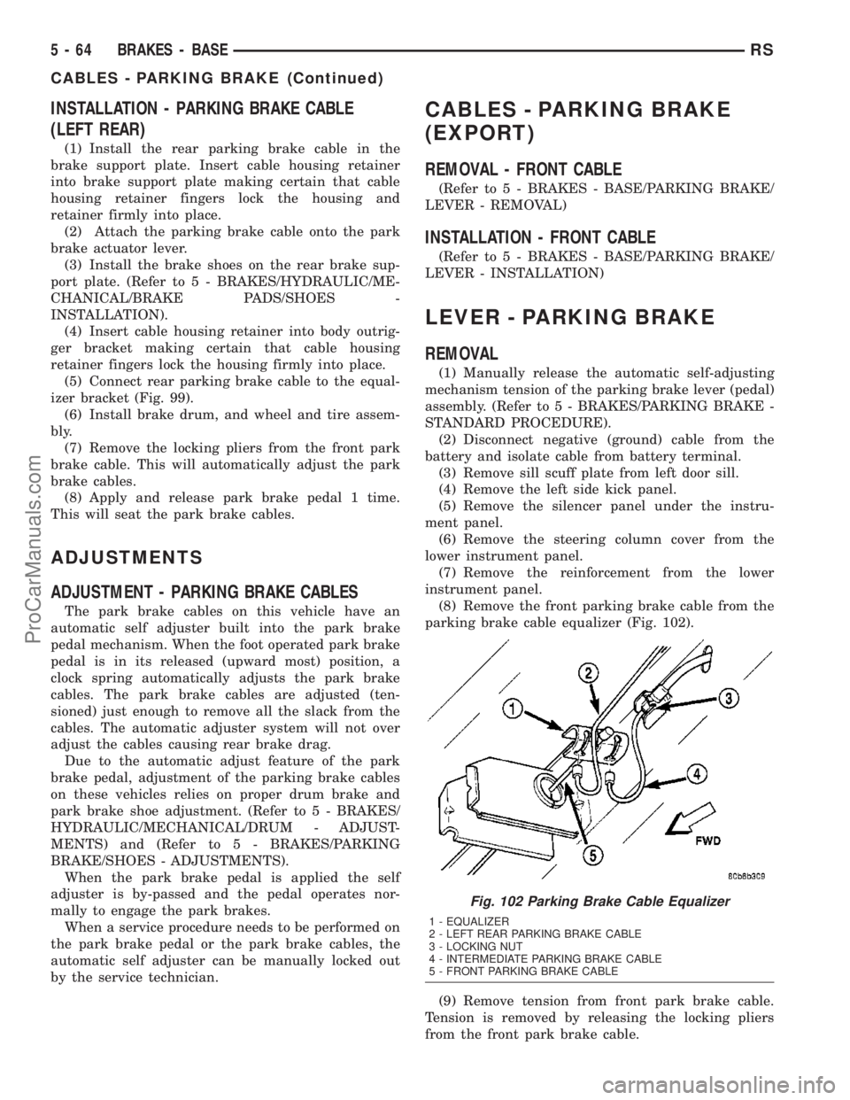
parking brake cable equalizer (Fig. 102).
(9) Remove tension from front park brake cable.
Tension is removed by releasing the locking pliers
from the front park brake cable.
Fig. 102 Parking Brake Cable Equalizer
1 - EQUALIZER
2 - LEFT REAR PARKING BRAKE CABLE
3 - LOCKING NUT
4 - INTERMEDIATE PARKING BRAKE CABLE
5 - FRONT PARKING BRAKE CABLE
5 - 64 BRAKES - BASERS
CABLES - PARKING BRAKE (Continued)
ProCarManuals.com
Page 220 of 2177

(13) AWD only - Install the wheel speed sensor on
the hub/bearing and adapter. Install the wheel speed
sensor attaching bolt (Fig. 115). Tighten the wheel
speed sensor attaching bolt to a torque of 12 N´m
(105 in. lbs).
(14) FWD only - Install the wheel speed sensor in
the following fashion:
(a) If metal wheel speed sensor retaining clip is
not in the neutral installed position on hub and
bearing cap, install from the bottom, if necessary,
and push clip upward until it snaps into position.
(b) Install wheel speed sensor head into rear of
hub and bearing aligning index tab with the notch
in the top of the mounting hole. Push the sensor in
until it snaps into place on the metal retaining
clip.
(c) Install secondary (yellow) retaining clip over
wheel speed sensor head and engage the tabs on
each side.
(15) Install the park brake cable into its mounting
hole in the adapter.Be sure all the locking tabs
on the park brake cable retainer are expanded
out to ensure the cable will not pull out of the
adapter.
(16) Install the end of the park brake cable on the
park brake actuator lever (Fig. 113).
(17) Attach park brake cable to adapter using
mounting bolt.
(18) Remove the locking pliers (Fig. 109) from the
front park brake cable.
(19) Adjust the park brake drum-in-hat brake
shoes. (Refer to 5 - BRAKES/PARKING BRAKE/
SHOES - ADJUSTMENTS).
(20) Install the rotor on the hub/bearing.
(21) Carefully lower caliper and brake shoes over
rotor and onto the adapter using the reverse proce-
dure for removal (Fig. 111).
CAUTION: When installing guide pin bolts extreme
caution should be taken not to crossthread the cal-
iper guide pin bolts.
(22) Install the caliper guide pin bolts (Fig. 110).
Tighten the guide pin bolts to a torque of 35 N´m (26
ft. lbs.).
(23) AWD only - Clean all foreign material off the
threads of the outer C/V joint stub shaft. Install the
washer and hub nut (Fig. 108) on the stub shaft of
the outer C/V joint.
(24) AWD only - Set the parking brake.
(25) AWD only - Tighten the hub nut to a torque of
244 N´m (180 ft. lbs.).
(26) AWD only - Install the spring washer (Fig.
107) on the stub shaft of the outer C/V joint.
(27) AWD only - Install the nut retainer and cotter
pin (Fig. 106) on the stub shaft of the outer C/V joint.(28) Install the wheel and tire assembly. Tighten
the wheel mounting stud nuts in proper sequence
until all nuts are torqued to half specification. Then
repeat the tightening sequence to the full specified
torque of 135 N´m (100 ft. lbs.).
(29) Lower vehicle.
(30) Fully apply and release the park brake pedal
one time. This will seat and correctly adjust the park
brake cables.
CAUTION: Before moving vehicle, pump the brake
pedal several times to insure the vehicle has a firm
brake pedal to adequately stop vehicle.
(31) Road test the vehicle and make several stops
to wear off any foreign material on the brakes and to
seat the brake shoe linings.
ADJUSTMENTS
ADJUSTMENT - PARKING BRAKE SHOES
CAUTION: Before adjusting the park brake shoes be
sure that the park brake pedal is in the fully
released position. If park brake pedal is not in the
fully released position, the park brake shoes can
not be accurately adjusted.
(1) Raise vehicle.
(2) Remove tire and wheel.
(3) Remove disc brake caliper from caliper adapter
(Fig. 128). (Refer to 5 - BRAKES/HYDRAULIC/ME-
CHANICAL/DISC BRAKE CALIPERS - REMOVAL).
(4) Remove rotor from hub/bearing.
Fig. 128 Disc Brake Caliper
1 - DISC BRAKE CALIPER
2 - ADAPTER
3 - AXLE
4 - GUIDE PIN BOLTS
5 - DRIVESHAFT (AWD MODELS ONLY)
RSBRAKES - BASE5-73
SHOES - PARKING BRAKE (Continued)
ProCarManuals.com
Page 421 of 2177
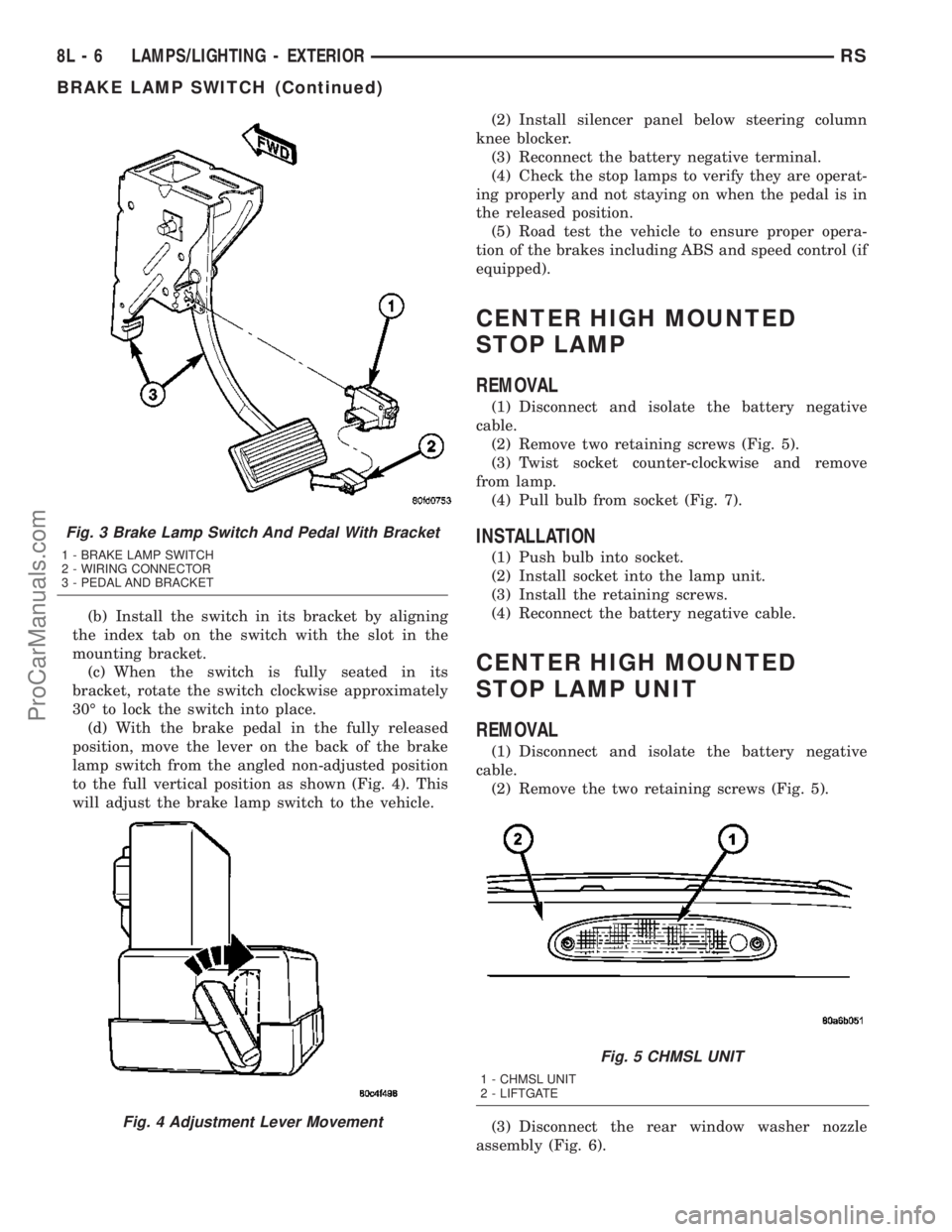
(b) Install the switch in its bracket by aligning
the index tab on the switch with the slot in the
mounting bracket.
(c) When the switch is fully seated in its
bracket, rotate the switch clockwise approximately
30É to lock the switch into place.
(d) With the brake pedal in the fully released
position, move the lever on the back of the brake
lamp switch from the angled non-adjusted position
to the full vertical position as shown (Fig. 4). This
will adjust the brake lamp switch to the vehicle.(2) Install silencer panel below steering column
knee blocker.
(3) Reconnect the battery negative terminal.
(4) Check the stop lamps to verify they are operat-
ing properly and not staying on when the pedal is in
the released position.
(5) Road test the vehicle to ensure proper opera-
tion of the brakes including ABS and speed control (if
equipped).
CENTER HIGH MOUNTED
STOP LAMP
REMOVAL
(1) Disconnect and isolate the battery negative
cable.
(2) Remove two retaining screws (Fig. 5).
(3) Twist socket counter-clockwise and remove
from lamp.
(4) Pull bulb from socket (Fig. 7).
INSTALLATION
(1) Push bulb into socket.
(2) Install socket into the lamp unit.
(3) Install the retaining screws.
(4) Reconnect the battery negative cable.
CENTER HIGH MOUNTED
STOP LAMP UNIT
REMOVAL
(1) Disconnect and isolate the battery negative
cable.
(2) Remove the two retaining screws (Fig. 5).
(3) Disconnect the rear window washer nozzle
assembly (Fig. 6).
Fig. 3 Brake Lamp Switch And Pedal With Bracket
1 - BRAKE LAMP SWITCH
2 - WIRING CONNECTOR
3 - PEDAL AND BRACKET
Fig. 4 Adjustment Lever Movement
Fig. 5 CHMSL UNIT
1 - CHMSL UNIT
2 - LIFTGATE
8L - 6 LAMPS/LIGHTING - EXTERIORRS
BRAKE LAMP SWITCH (Continued)
ProCarManuals.com
Page 456 of 2177
POWER SYSTEMS
TABLE OF CONTENTS
page page
POWER LIFTGATE SYSTEM.................. 1
POWER SLIDING DOOR SYSTEM............ 19
POWER LOCKS........................... 38POWER MIRRORS........................ 45
POWER SEAT SYSTEM..................... 50
POWER WINDOWS........................ 62
POWER LIFTGATE SYSTEM
TABLE OF CONTENTS
page page
POWER LIFTGATE SYSTEM
DESCRIPTION..........................2
OPERATION............................3
DIAGNOSIS AND TESTING - POWER
LIFTGATE SYSTEM.....................4
STANDARD PROCEDURE
STANDARD PROCEDURE - LIFTGATE
ADJUSTMENT.........................9
STANDARD PROCEDURE - POWER
LIFTGATE LEARN CYCLE................9
SPECIFICATIONS
SPECIFICATIONS TABLE................9
CHIME/THERMISTOR
DESCRIPTION.........................10
OPERATION...........................10
REMOVAL.............................10
INSTALLATION.........................10
ENGAGE ACTUATOR
DESCRIPTION.........................10
OPERATION...........................11
REMOVAL.............................11
INSTALLATION.........................11
EXTERIOR HANDLE SWITCH
DESCRIPTION.........................11
OPERATION...........................11
REMOVAL.............................11
INSTALLATION.........................12
FULL OPEN SWITCH
DESCRIPTION.........................12
OPERATION...........................12
REMOVAL.............................13INSTALLATION.........................13
LATCH
DESCRIPTION.........................13
OPERATION...........................13
REMOVAL.............................13
INSTALLATION.........................14
LATCH ACTUATOR
DESCRIPTION.........................14
OPERATION...........................14
REMOVAL.............................14
INSTALLATION.........................14
LIFTGATE MOTOR
DESCRIPTION.........................15
OPERATION...........................15
REMOVAL.............................15
INSTALLATION.........................15
LIFT GEAR & LINK ROD
DESCRIPTION.........................16
OPERATION...........................16
REMOVAL.............................16
INSTALLATION.........................16
PINCH SENSOR
DESCRIPTION.........................17
OPERATION...........................17
REMOVAL.............................17
INSTALLATION.........................17
TRANSVERSE BRACKET
DESCRIPTION.........................18
OPERATION...........................18
REMOVAL.............................18
INSTALLATION.........................18
RSPOWER SYSTEMS8N-1
ProCarManuals.com
Page 513 of 2177
(3) Reconnect the power seat wire harness connec-
tor to the power seat switch connector receptacle.
(4) Position the outboard seat cushion side shield
onto the seat cushion frame
(5) Install and tighten the screws that secure the
outboard seat cushion side shield to the seat cushion
frame. Tighten the screws to 1.5 N´m (14 in. lbs.).
(6) Install the switch knobs on the switch control
levers, if equipped.
(7) Reconnect the battery negative cable.
DRIVER POWER SEAT TRACK
DESCRIPTION
The eight-way driver side power seat option
includes a electrically operated power seat track
located under the driver side front seat. The front
power seat track on the driver side of the vehicle also
provides the mounting location for the Memory Seat/
Mirror Module (MSMM). The power seat circuit
breakers are mounted on the rear of the driver side
power seat track, just behind the seat rear trim
panel. The lower half of the power seat track is
secured to the floor panel via four studs and nuts
that must be accessed from the underside of the vehi-
cle. Four bolts secure the bottom of the seat cushion
pan to the upper half of the power seat track unit.
Four additional bolts secure the seat back frame to
the power seat track unit.
The power seat track unit includes four reversible
electric motors that are secured to the upper half of
the track unit. Each motor moves the seat adjuster
through a combination of worm-drive gearboxes and
screw-type drive units. Each of the four power seat
track motors used on models equipped with the
optional memory system incorporates a position
potentiometer integral to the motor assembly, which
electronically monitors the motor position. This
enables the memory system to function by referenc-
ing the motor positions programmed into the memory
seat/mirror module.
The front and rear of the seat are operated by two
separate vertical adjustment motors. These motors
can be operated independently of each other, tilting
the entire seat assembly forward or rearward; or,
they can be operated in unison by selecting the
proper power seat switch functions, which will raise
or lower the entire seat assembly. A third motor is
the horizontal adjustment motor, which moves the
seat track in the forward and rearward directions.
The forth motor is the recliner adjustment motor,
which moves the seat back in the forward and rear-
ward directions.
The power seat track unit cannot be repaired, and
is serviced only as a complete unit. If any componentin this unit is faulty or damaged, the entire power
seat track unit must be replaced.
OPERATION
When the driver side power seat switch control
knob or knobs are actuated, a battery feed and a
ground path are applied through the switch contacts
to the power seat track or recliner adjuster motor.
The selected adjuster motor operates to move the
seat track or recliner through its drive unit in the
selected direction until the switch is released, or
until the travel limit of the adjuster is reached.
When the switch is moved in the opposite direction,
the battery feed and ground path to the motor are
reversed through the switch contacts. This causes the
adjuster motor to run in the opposite direction.
No power seat switch should be held applied in any
direction after the adjuster has reached its travel
limit. The power seat adjuster motors each contain a
self-resetting circuit breaker to protect them from
overload. However, consecutive or frequent resetting
of the circuit breaker must not be allowed to con-
tinue, or the motor may be damaged.
See the owner's manual in the vehicle glove box for
more information on the power seat switch functions
and the seat adjusting procedures.
DIAGNOSIS AND TESTING - DRIVER POWER
SEAT TRACK
WARNING: SOME VEHICLES ARE EQUIPPED WITH
SEATBACK MOUNTED AIRBAGS. BEFORE
ATTEMPTING TO DIAGNOSE OR SERVICE ANY
SEAT OR POWER SEAT SYSTEM COMPONENT
YOU MUST FIRST DISCONNECT AND ISOLATE THE
BATTERY NEGATIVE CABLE. THEN WAIT TWO MIN-
UTES FOR THE SYSTEM CAPACITOR TO DIS-
CHARGE BEFORE FURTHER SYSTEM SERVICE.
THIS IS THE ONLY SURE WAY TO DISABLE THE
AIRBAG SYSTEM. FAILURE TO DO SO COULD
RESULT IN ACCIDENTAL AIRBAG DEPLOYMENT
AND POSSIBLE PERSONAL INJURY.
Actuate the driver side power seat switch to move
all three power seat track adjusters in each direction.
The power seat track adjusters should move in each
of the selected directions. If a power seat track
adjuster fails to operate in only one direction, move
the adjuster a short distance in the opposite direction
and test again to be certain that the adjuster is not
at its travel limit. If the power seat track adjuster
still fails to operate in only one direction, refer to
Diagnosis and Testing Power Seat Switchin this
section. If the power seat track adjuster fails to oper-
ate in more than one direction, perform the following
tests. For complete circuit diagrams, refer toWiring
Diagrams.
8N - 58 POWER SEAT SYSTEMRS
PASSENGER SEAT SWITCH (Continued)
ProCarManuals.com
Page 514 of 2177
TESTING POWER SEAT TRACK MOTORS
(1) Check the power seat circuit breaker under the
seat. If OK, go to Step 2. If not OK, replace the
faulty power seat circuit breaker.
(2) Check for battery voltage at the power seat cir-
cuit breaker under the seat. If OK, go to Step 3. If
not OK, repair the open fused B(+) circuit to the fuse
in the Intelligent Power Module as required.
(3) Remove the outboard seat cushion side shield
from the seat. Disconnect the seat wire harness con-
nector from the power seat switch connector recepta-
cle. Check for battery voltage at the fused B(+)
circuit cavity of the power seat wire harness connec-
tor for the power seat switch. If OK, go to Step 4. If
not OK, repair the open fused B(+) circuit to the
power seat circuit breaker under the seat as
required.
(4) Check for continuity between the ground cir-
cuit cavity of the power seat wire harness connector
for the power seat switch and a good ground. There
should be continuity. If OK, go to Step 5. If not OK,
repair the open ground circuit to ground as required.
(5) Test the power seat switch. Refer toDiagnosis
and Testing Power Seat Switchin this section. If
the switch tests OK, test the circuits of the power
seat wire harness between the inoperative power seat
track adjuster motor and the power seat switch for
shorts or opens. If the circuits check OK, replace the
faulty power seat track unit. If the circuits are not
OK, repair the power seat wire harness as required.
REMOVAL
WARNING: SOME VEHICLES ARE EQUIPPED WITH
SEATBACK MOUNTED AIRBAGS. BEFORE
ATTEMPTING TO DIAGNOSE OR SERVICE ANY
SEAT OR POWER SEAT SYSTEM COMPONENT
YOU MUST FIRST DISCONNECT AND ISOLATE THE
BATTERY NEGATIVE CABLE. THEN WAIT TWO MIN-
UTES FOR THE SYSTEM CAPACITOR TO DIS-
CHARGE BEFORE FURTHER SYSTEM SERVICE.
THIS IS THE ONLY SURE WAY TO DISABLE THE
AIRBAG SYSTEM. FAILURE TO DO SO COULD
RESULT IN ACCIDENTAL AIRBAG DEPLOYMENT
AND POSSIBLE PERSONAL INJURY.
(1) Remove the appropriate seat from the vehicle
and place it on a clean work surface(Refer to 23 -
BODY/SEATS/SEAT - REMOVAL).
(2) If the vehicle is so equipped, remove the Mem-
ory Seat/Mirror Module (MSMM) retaining screws.
(3) If the vehicle is so equipped, disconnect the
MSMM electrical connectors and remove the MSMM
from the power seat track.
(4) Remove the rear fabric blocker trim panel from
the rear of the front seat.(5) Remove the seat side cover and power seat
switch as an assembly (Refer to 23 - BODY/SEATS/
SEAT CUSHION SIDE COVERS - REMOVAL).
(6) Disconnect all electrical connectors connecting
the power seat track to the seat assembly.
(7) Pull the seat back trim cover up slightly to
access and remove the two seat back frame mounting
bolts and also remove two seat back recliner bolts.
(8) Remove four seat track mounting bolts from
the seat cushion pan.
(9) Remove the power seat track from the seat.
INSTALLATION
(1) Position the seat cushion on the seat track.
(2) Install the four seat track retaining bolts in the
seat cushion pan. Torque the bolts to 28.5 N´m.
(3) Position the seat back and install the two seat
back frame mounting bolts and the two seat back
recliner bolts. Torque the bolts to 55 N´m.
(4) Route and connect the electrical connectors
between the power seat track and the seat assembly.
(5) Install the seat side cover and power seat
switch as an assembly (Refer to 23 - BODY/SEATS/
SEAT CUSHION SIDE COVERS - INSTALLATION).
(6) Install the rear fabric blocker trim panel on the
rear of the front seat.
(7) If the vehicle is so equipped, position the Mem-
ory Seat/Mirror Module (MSMM) and connect the
MSMM electrical connectors.
(8) Install the MSMM retaining screws.
(9) Install the seat assembly in the vehicle (Refer
to 23 - BODY/SEATS/SEAT - INSTALLATION).
PASSENGER POWER SEAT
TRACK
DESCRIPTION
The four-way passenger side power seat option
includes a electrically operated power seat track unit
located under the passenger side front seat. The
power seat circuit breaker is mounted on the rear of
the power seat track, just behind the seat rear trim
panel. The lower half of the power seat track is
secured to the floor panel via four studs and nuts
that must be accessed from the underside of the vehi-
cle. Four bolts secure the bottom of the seat cushion
frame to the upper half of the power seat track unit.
Four additional bolts secure the seat back frame to
the power seat track unit.
The passenger side power seat track unit includes
two reversible electric motors that are secured to the
upper half of the track unit. Each motor moves the
seat adjuster through a combination of worm-drive
gearboxes and screw-type drive units. The horizontal
adjustment motor moves the seat track in the for-
RSPOWER SEAT SYSTEM8N-59
DRIVER POWER SEAT TRACK (Continued)
ProCarManuals.com
Page 1245 of 2177

ting notch and spring tang should remain aligned
after lock nut is torqued.
(6) Remove allen wrench and torque wrench.
NOTE: Repositioning the crankshaft to the TDC
position must be done only during the CLOCKWISE
rotation movement. If TDC is missed, rotate a fur-
ther two revolutions until TDC is achieved. DO NOT
rotate crankshaft counterclockwise as this will
make verification of proper tensioner setting impos-
sible.
(7) Rotate the crankshaft CLOCKWISE two com-
plete revolutions manually for seating of the belt,
until the crankshaft is repositioned at the TDC posi-
tion. Verify that the camshaft and crankshaft timing
marks are in proper position (Fig. 124).
Fig. 121 Camshaft Sprocket Alignment
1 - CAMSHAFT SPROCKET-EXHAUST
2 - CAMSHAFT SPROCKET-INTAKE
3 - 1/2 NOTCH LOCATION
Fig. 122 Timing Belt Installation
1 - CAMSHAFT TIMING MARKS 1/2 NOTCH LOCATION
2 - CRANKSHAFT AT TDC
3 - INSTALL BELT IN THIS DIRECTION
4 - ROTATE CAMSHAFT SPROCKET TO TAKE UP BELT SLACK
Fig. 123 Timing Belt Tension Adjustment
1 - ALIGN SETTING NOTCH WITH SPRING TANG
2 - TOP PLATE
3 - 6mm ALLEN WRENCH
4 - LOCK BOLT
5 - SETTING NOTCH
6 - SPRING TANG
9 - 66 ENGINE 2.4LRS
TIMING BELT AND SPROCKET(S) (Continued)
ProCarManuals.com
Page 1646 of 2177

(17) Apply a bead of MopartSilicone Rubber
Adhesive Sealant to differential cover and install to
case (Fig. 205).
(18) Install and torque cover-to-case bolts to 19
N´m (165 in. lbs.) (Fig. 206).
ADJUSTMENTS
ADJUSTMENT - DIFFERENTIAL BEARING
PRELOAD
NOTE: Perform all differential bearing preload mea-
surements with the transfer shaft and gear
removed.
DIFFERENTIAL BEARING PRELOAD ADJUSTMENT
USING EXISTING SHIM
(1) Position the transaxle assembly vertically on
the support stand, differential bearing retainer side
up.
(2) Install Tool L-4436A into the differential and
onto the pinion mate shaft (Fig. 207).
(3) Rotate the differential at least one full revolu-
tion to ensure the tapered roller bearings are fully
seated.
(4) Using Tool L-4436A and an inch-pound torque
wrench, check the turning torque of the differential
(Fig. 208).The turning torque should be
between 5 and 18 inch-pounds.
Fig. 205 Install Differential Cover
1 - DIFFERENTIAL ASSEMBLY
2 - DIFFERENTIAL COVER
Fig. 206 Differential Cover Bolts
1 - DIFFERENTIAL COVER BOLTS
2 - DIFFERENTIAL COVER
Fig. 207 Tool L-4436 and Torque Wrench
1 - SPECIAL TOOL L-4436±A
2 - TORQUE WRENCH
3 - DIFFERENTIAL BEARING RETAINER
Fig. 208 Checking Differential Bearings Turning
Torque
1 - SPECIAL TOOL L-4436±A
2 - TORQUE WRENCH
RS41TE AUTOMATIC TRANSAXLE21 - 199
FINAL DRIVE (Continued)
ProCarManuals.com