torque CHRYSLER VOYAGER 2004 Service Manual
[x] Cancel search | Manufacturer: CHRYSLER, Model Year: 2004, Model line: VOYAGER, Model: CHRYSLER VOYAGER 2004Pages: 2585, PDF Size: 62.54 MB
Page 285 of 2585
(24) Install knee blocker reinforcement plate (Fig.
53). (25) Connect parking brake release link to release
handle. (26) Install data link diagnostic connector to
mounting hole in reinforcement plate. (27) Install lower steering column cover/knee
blocker (Fig. 53). (28) Install throttle cable onto throttle body lever.
(Refer to 14 - FUEL SYSTEM/FUEL INJECTION/
THROTTLE CONTROL CABLE - INSTALLATION)
NOTE: When reconnecting the battery on a vehicle
that has had the airbag module removed, the fol-
lowing procedure should be used.
(29) Reconnect ground cable to negative post of
battery following special Diagnosis And Testing pro-
cedure. (Refer t o 8 - ELECTRICAL/RESTRAINTS -
DIAGNOSIS AND TESTING) (30) Test operation of adjustable pedals and all
functions that are steering column operated. If appli-
cable, reset radio and clock. (31) Road test the vehicle to ensure proper opera-
tion of steering and brake systems.
PEDAL TORQUE SHAFT - RHD
REMOVAL
(1) Remove the instrument panel. (Refer to 23 -
BODY/INSTRUMENT PANEL/INSTRUMENT
PANEL ASSEMBLY - REMOVAL) (2) Remove the HVAC housing. (Refer to 24 -
HEATING & AIR CONDITIONING/DISTRIBUTION/
HVAC HOUSING - REMOVAL) (3) Remove the retaining clip at the torque shaft
end of the brake pedal-to-torque shaft link. Remove
the link from the torque shaft. Discard the retaining
clip. It is not to be reused. Replace with a new clip
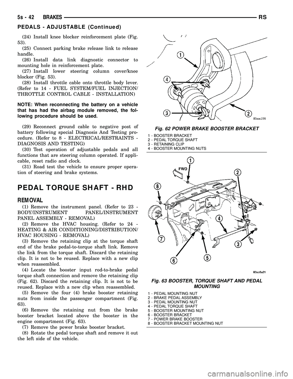
when reassembled. (4) Locate the booster input rod-to-brake pedal
torque shaft connection and remove the retaining clip
(Fig. 62). Discard the retaining clip. It is not to be
reused. Replace with a new clip when reassembled. (5) Remove the four (4) brake booster retaining
nuts from inside the passenger compartment (Fig.
63). (6) Remove the retaining nut from the brake
booster bracket located above the booster in the
engine compartment (Fig. 63). (7) Remove the power brake booster bracket.
(8) Rotate the pedal torque shaft and remove it out
the left side of the vehicle.
Fig. 62 POWER BRAKE BOOSTER BRACKET
1 - BOOSTER BRACKET
2 - PEDAL TORQUE SHAFT
3 - RETAINING CLIP
4 - BOOSTER MOUNTING NUTS
Fig. 63 BOOSTER, TORQUE SHAFT AND PEDAL MOUNTING
1 - PEDAL MOUNTING NUT
2 - BRAKE PEDAL ASSEMBLY
3 - PEDAL MOUNTING NUT
4 - PEDAL TORQUE SHAFT
5 - BOOSTER MOUNTING NUT
6 - BOOSTER BRACKET
7 - POWER BRAKE BOOSTER
8 - BOOSTER BRACKET MOUNTING NUT
5s - 42 BRAKESRS
PEDALS - ADJUSTABLE (Continued)
Page 286 of 2585
INSTALLATION
(1) Lubricate both ends of the torque shaft with
MS-4517 Lubricant or equivalent and install the
torque shaft from the left side reversing the removal
procedure. (2) Install the brake booster bracket on the left
end of the shaft. (3) Install the retaining nut for the brake booster
bracket in the engine compartment. Tighten the
mounting nut to a torque of 29 N´m (250 in. lbs.). (4) Install the four brake booster retaining nuts
inside the passenger compartment. Tighten the
mounting nuts to a torque of 29 N´m (250 in. lbs.). (5) Using lubriplate, or equivalent, coat the sur-
face of the brake pedal torque shaft pin where it con-
tacts the booster input rod. Also coat the surface of
the brake pedal torque shaft pin where it contacts
the brake pedal link.
CAUTION: When installing the power brake booster
input rod on the brake pedal torque shaft pin, do
not reuse the old retaining clip.
(6) Install booster input rod on brake pedal torque
shaft pin and install a NEW retaining clip (Fig. 62).
CAUTION: When installing the brake pedal link on
the brake pedal torque shaft pin, do not reuse the
old retaining clip.
(7) Connect the brake pedal link to the torque
shaft. Install a NEW retaining clip at the torque
shaft end of the brake pedal-to-torque shaft link. (8) Install the HVAC housing. (Refer to 24 - HEAT-
ING & AIR CONDITIONING/DISTRIBUTION/HVAC
HOUSING - INSTALLATION) (9) Install the instrument panel. (Refer to 23 -
BODY/INSTRUMENT PANEL/INSTRUMENT
PANEL ASSEMBLY - INSTALLATION)
CAUTION: Do not reuse the original brake lamp
switch. The switch can only be adjusted once. That
is during initial installation of the switch. If the
switch is not adjusted properly or has been
removed for some service, a new switch must be
installed and adjusted.
(10) Remove and replace the brake lamp switch
with a NEW switch. (Refer t o 8 - ELECTRICAL/
LAMPS/LIGHTING - EXTERIOR/BRAKE LAMP
SWITCH - REMOVAL), (Refer t o 8 - ELECTRICAL/
LAMPS/LIGHTING - EXTERIOR/BRAKE LAMP
SWITCH - INSTALLATION) (11) Road test vehicle to ensure proper operation of
the brakes.
POWER BRAKE BOOSTER
DESCRIPTION
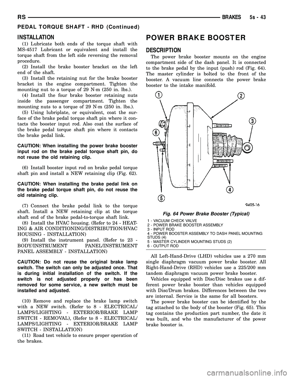
The power brake booster mounts on the engine
compartment side of the dash panel. It is connected
to the brake pedal by the input (push) rod (Fig. 64).
The master cylinder is bolted to the front of the
booster. A vacuum line connects the power brake
booster to the intake manifold.
All Left-Hand-Drive (LHD) vehicles use a 270 mm
single diaphragm vacuum power brake booster. All
Right-Hand-Drive (RHD) vehicles use a 225/200 mm
tandem diaphragm vacuum power brake booster. Vehicles equipped with Disc/Disc brakes use a dif-
ferent power brake booster than vehicles equipped
with Disc/Drum brakes. Differences between the two
are internal. Service is the same for all boosters. The power brake booster can be identified by the
tag attached to the body of the booster (Fig. 65). This
tag contains the production part number, the date it
was built, and who the manufacturer of the power
brake booster is.
Fig. 64 Power Brake Booster (Typical)
1 - VACUUM CHECK VALVE
2 - POWER BRAKE BOOSTER ASSEMBLY
3 - INPUT ROD
4 - POWER BOOSTER ASSEMBLY TO DASH PANEL MOUNTING
STUDS (4)
5 - MASTER CYLINDER MOUNTING STUDS (2)
6 - OUTPUT ROD
RS BRAKES5s-43
PEDAL TORQUE SHAFT - RHD (Continued)
Page 291 of 2585
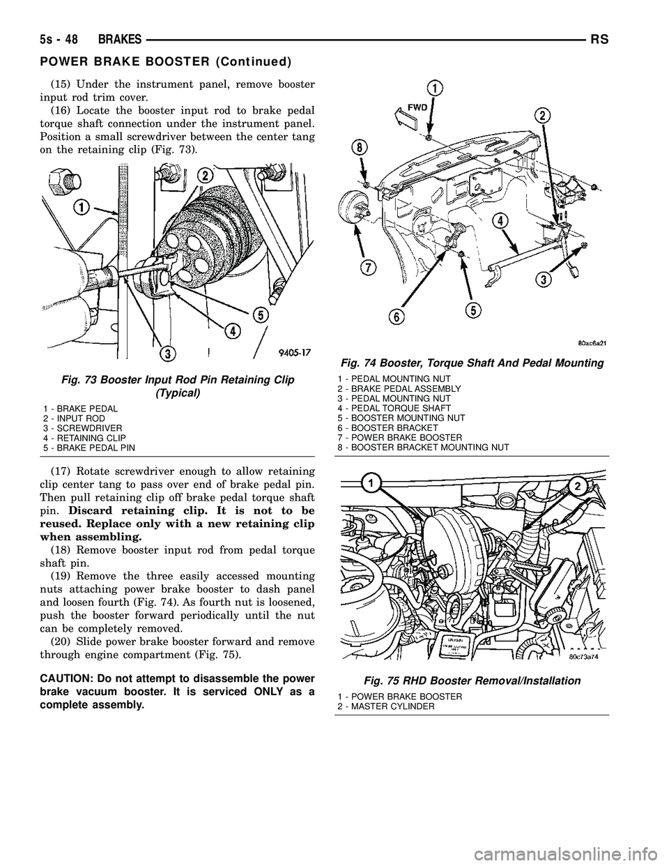
(15) Under the instrument panel, remove booster
input rod trim cover. (16) Locate the booster input rod to brake pedal
torque shaft connection under the instrument panel.
Position a small screwdriver between the center tang
on the retaining clip (Fig. 73).
(17) Rotate screwdriver enough to allow retaining
clip center tang to pass over end of brake pedal pin.
Then pull retaining clip off brake pedal torque shaft
pin. Discard retaining clip. It is not to be
reused. Replace only with a new retaining clip
when assembling. (18) Remove booster input rod from pedal torque
shaft pin. (19) Remove the three easily accessed mounting
nuts attaching power brake booster to dash panel
and loosen fourth (Fig. 74). As fourth nut is loosened,
push the booster forward periodically until the nut
can be completely removed. (20) Slide power brake booster forward and remove
through engine compartment (Fig. 75).
CAUTION: Do not attempt to disassemble the power
brake vacuum booster. It is serviced ONLY as a
complete assembly.
Fig. 73 Booster Input Rod Pin Retaining Clip (Typical)
1 - BRAKE PEDAL
2 - INPUT ROD
3 - SCREWDRIVER
4 - RETAINING CLIP
5 - BRAKE PEDAL PIN
Fig. 74 Booster, Torque Shaft And Pedal Mounting
1 - PEDAL MOUNTING NUT
2 - BRAKE PEDAL ASSEMBLY
3 - PEDAL MOUNTING NUT
4 - PEDAL TORQUE SHAFT
5 - BOOSTER MOUNTING NUT
6 - BOOSTER BRACKET
7 - POWER BRAKE BOOSTER
8 - BOOSTER BRACKET MOUNTING NUT
Fig. 75 RHD Booster Removal/Installation
1 - POWER BRAKE BOOSTER
2 - MASTER CYLINDER
5s - 48 BRAKESRS
POWER BRAKE BOOSTER (Continued)
Page 292 of 2585

INSTALLATION
INSTALLATION - LHD
(1) Position power brake booster on dash panel
using the reverse procedure of its removal (Fig. 70).
It may be necessary to push in on booster input rod
as it is guided through the dash panel. (2) Install the four nuts mounting the booster to
the dash panel (Fig. 69). Tighten the mounting nuts
to a torque of 29 N´m (250 in. lbs.). (3) Using lubriplate, or equivalent, coat the sur-
face of the brake pedal pin where it contacts the
booster input rod.
CAUTION: When installing the brake pedal pin on
the power brake booster input rod, do not re-use
the old retaining clip.
(4) Install booster input rod on brake pedal pin
and install a NEW retaining clip (Fig. 76).
CAUTION: Do not reuse the original brake lamp
switch. The switch can only be adjusted once. That
is during initial installation of the switch. If the
switch is not adjusted properly or has been
removed for some service, a new switch must be
installed and adjusted.
(5) Remove and replace the brake lamp switch
with a NEW switch. (Refer t o 8 - ELECTRICAL/
LAMPS/LIGHTING - EXTERIOR/BRAKE LAMP
SWITCH - REMOVAL), (Refer t o 8 - ELECTRICAL/
LAMPS/LIGHTING - EXTERIOR/BRAKE LAMP
SWITCH - INSTALLATION) (6) Install the silencer panel below the steering
column. (7) Connect vacuum hose to check valve on power
brake booster.
CAUTION: The master cylinder (and its rear seal) is
used to create the seal for holding vacuum in the
vacuum booster. The vacuum seal on the master
cylinder MUST be replaced with a NEW seal when-
ever the master cylinder is removed from the vac-
uum booster.
CAUTION: When removing the vacuum seal from
the master cylinder do not use a sharp tool.
(8) Using a soft tool such as a trim stick, remove
the vacuum seal from the master cylinder mounting
flange. (9) Install a NEW vacuum seal on rear mounting
flange of the master cylinder (Fig. 77).
(10) Position master cylinder on studs of booster,
aligning push rod on booster with master cylinder
piston. (11) Install the two nuts mounting the master cyl-
inder to the booster (Fig. 67). Tighten both mounting
nuts to a torque of 25 N´m (225 in. lbs.). (12) Connect wiring harness connector to brake
fluid level switch in the master cylinder fluid reser-
voir (Fig. 66). (13) Connect primary and secondary brake tubes
to ABS ICU or non-ABS junction block (Fig. 67).
Tighten the tube nuts to 17 N´m (145 in lbs.). (14) Install wiper module (unit). (Refer to 8 -
ELECTRICAL/WIPERS/WASHERS/WIPER MOD-
ULE - INSTALLATION) (15) If equipped with speed control, install speed
control servo and connect wiring connector. Tighten
Fig. 76 Retaining Pin Installed On Brake Pedal Pin
1 - BRAKE PEDAL
2 - RETAINING CLIP
3 - BOOSTER INPUT ROD
Fig. 77 Vacuum Seal (Typical)
1 - MASTER CYLINDER ASSEMBLY
2 - VACUUM SEAL
RS BRAKES5s-49
POWER BRAKE BOOSTER (Continued)
Page 293 of 2585
the mounting nuts to a torque of 14 N´m (124 in.
lbs.).(16) Install the battery tray. Install the two nuts
and one bolt attaching the battery tray to the vehicle.
Tighten the bolt and nuts to a torque of 14 N´m (124
in. lbs.). (17) If vehicle is equipped with speed control, con-
nect the servo vacuum hose to the vacuum tank on
the battery tray. (18) Install the air inlet resonator and hoses as an
assembly on the throttle body and air cleaner hous-
ing. Securely tighten hose clamp at air cleaner hous-
ing and throttle body. (19) Secure the engine coolant filler neck to the
battery tray with its mounting screw. (20) Install the battery, clamp and mounting nut.
(21) Install the positive battery cable on the bat-
tery. (22) Install the negative battery cable on the bat-
tery. (23) Install the battery thermal guard shield.
(24) Bleed the base brakes as necessary. (Refer to
5 - BRAKES - STANDARD PROCEDURE) (25) Road test vehicle to ensure operation of the
brakes.
INSTALLATION - RHD
(1) Position power brake booster on dash panel
using the reverse procedure of its removal (Fig. 75). (2) Below instrument panel, first install the two
upper nuts mounting the booster to the dash panel,
drawing it into place, then install the two lower
mounting nuts. Tighten the mounting nuts to a
torque of 29 N´m (250 in. lbs.). (3) Using lubriplate, or equivalent, coat the sur-
face of the brake pedal torque shaft pin where it con-
tacts the booster input rod.
CAUTION: When installing the brake pedal torque
shaft pin on the power brake booster input rod, do
not re-use the old retaining clip.
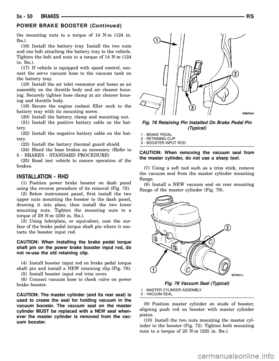
(4) Install booster input rod on brake pedal torque
shaft pin and install a NEW retaining clip (Fig. 78). (5) Install booster input rod trim cover.
(6) Connect vacuum hose to check valve on power
brake booster.
CAUTION: The master cylinder (and its rear seal) is
used to create the seal for holding vacuum in the
vacuum booster. The vacuum seal on the master
cylinder MUST be replaced with a NEW seal when-
ever the master cylinder is removed from the vac-
uum booster. CAUTION: When removing the vacuum seal from
the master cylinder, do not use a sharp tool.
(7) Using a soft tool such as a trim stick, remove
the vacuum seal from the master cylinder mounting
flange. (8) Install a NEW vacuum seal on rear mounting
flange of the master cylinder (Fig. 79).
(9) Position master cylinder on studs of booster,
aligning push rod on booster with master cylinder
piston. (10) Install the two nuts mounting the master cyl-
inder to the booster (Fig. 72). Tighten both mounting
nuts to a torque of 25 N´m (225 in. lbs.).
Fig. 78 Retaining Pin Installed On Brake Pedal Pin (Typical)
1 - BRAKE PEDAL
2 - RETAINING CLIP
3 - BOOSTER INPUT ROD
Fig. 79 Vacuum Seal (Typical)
1 - MASTER CYLINDER ASSEMBLY
2 - VACUUM SEAL
5s - 50 BRAKESRS
POWER BRAKE BOOSTER (Continued)
Page 294 of 2585
(11) Connect wiring harness connector to brake
fluid level switch in the master cylinder fluid reser-
voir (Fig. 71). (12) If the vehicle is equipped with the 2.5L diesel
engine, install the coolant recovery pressure con-
tainer and bracket. (Refer t o 7 - COOLING/ENGINE/
COOLANT RECOVERY PRESS CONTAINER -
INSTALLATION) (13) If equipped with speed control, install speed
control servo and connect wiring connector. Tighten
the mounting nuts to a torque of 14 N´m (124 in.
lbs.). (14) Install the battery tray. Install the two nuts
and one bolt attaching the battery tray to the vehicle.
Tighten the bolt and nuts to a torque of 14 N´m (124
in. lbs.). (15) If vehicle is equipped with speed control, con-
nect the servo vacuum hose to the vacuum tank on
the battery tray. (16) Install the battery, clamp and mounting nut.
(17) Install the positive battery cable on the bat-
tery. (18) Install the negative battery cable on the bat-
tery. (19) Install the battery thermal guard shield.
CAUTION: Do not reuse the original brake lamp
switch. The switch can only be adjusted once. That
is during initial installation of the switch. If the
switch is not adjusted properly or has been
removed for some service, a new switch must be
installed and adjusted. (20) Remove and replace the brake lamp switch
with a NEW switch. (Refer t o 8 - ELECTRICAL/
LAMPS/LIGHTING - EXTERIOR/BRAKE LAMP
SWITCH - REMOVAL), (Refer t o 8 - ELECTRICAL/
LAMPS/LIGHTING - EXTERIOR/BRAKE LAMP
SWITCH - INSTALLATION) (21) Bleed the base brakes as necessary. (Refer to
5 - BRAKES - STANDARD PROCEDURE) (22) Road test vehicle to ensure proper operation
of the brakes.
PROPORTIONING VALVE
DESCRIPTION - PROPORTIONING VALVE
(HEIGHT SENSING)
NOTE: Only vehicles without antilock brakes (ABS)
have a proportioning valve. Vehicles with ABS uti-
lize electronic brake distribution which is controlled
through the ABS integrated control unit.
Vehicles not equipped with ABS use a height sens-
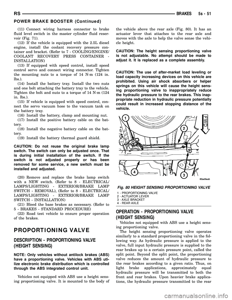
ing proportioning valve. It is mounted to the body of the vehicle above the rear axle (Fig. 80). It has an
actuator lever that attaches to the rear axle and
moves with the axle to help the valve sense the vehi-
cle height.
CAUTION: The height sensing proportioning valve
is not adjustable. No attempt should be made to
adjust it. It is replaced as a complete assembly.
CAUTION: The use of after-market load leveling or
load capacity increasing devices on this vehicle are
prohibited. Using air shock absorbers or helper
springs on this vehicle will cause the height sens-
ing proportioning valve to inappropriately reduce
the hydraulic pressure to the rear brakes. This inap-
propriate reduction in hydraulic pressure potentially
could result in increased stopping distance of the
vehicle.
OPERATION - PROPORTIONING VALVE
(HEIGHT SENSING)
Vehicles not equipped with ABS use a height sens-
ing proportioning valve. The height sensing proportioning valve operates
similarly to a standard proportioning valve in the fol-
lowing way. As hydraulic pressure is applied to the
valve, full input hydraulic pressure is supplied to the
rear brakes up to a certain pressure point, called the
split point. Beyond the split point, the proportioning
valve reduces the amount of hydraulic pressure to
the rear brakes according to a given ratio. Thus, on
light brake applications, approximately equal
hydraulic pressure will be transmitted to both the
front and rear brakes. Upon heavier brake applica-
tions, the hydraulic pressure transmitted to the rear
Fig. 80 HEIGHT SENSING PROPORTIONING VALVE
1 - PROPORTIONING VALVE
2 - ACTUATOR LEVER
3 - AXLE BRACKET
4 - REAR AXLE
RS BRAKES5s-51
POWER BRAKE BOOSTER (Continued)
Page 296 of 2585

CAUTION: Do not attempt to adjust the height sens-
ing proportioning valve. If found to be defective,
replace the valve.(9) Remove the pressure test fittings and pressure
gauges from the proportioning valve. (10) Install the chassis brake lines in the correct
ports of the proportioning valve. Tighten all tube
nuts to 17 N´m (145 in. lbs.). (11) If necessary, repeat the above steps on the
remaining side of the proportioning valve which con-
trol the other rear wheel brake. (12) Attach the actuator lever and bracket to the
rear axle. (13) Bleed rear brakes. (Refer t o 5 - BRAKES -
STANDARD PROCEDURE) (14) Road test vehicle.
PROPORTIONING VALVE SPECIFICATIONS
WHEELBASE DRIVE
TRAIN SALES
CODE BRAKE
SYSTEM SPLIT
POINT SLOPE INLET
PRESSURE PSI OUTLET
PRESSURE PSI
SWB FWD BRB-BGF 15
9DISC/
DRUM W/O ANTILOCK VAR. 0.59 1000 PSI 675-875 PSI
REMOVAL - PROPORTIONING VALVE (HEIGHT
SENSING)
(1) Using a brake pedal depressor, move and lock
the brake pedal to a position past its first 1 inch of
travel. This will prevent brake fluid from draining
out of the master cylinder when the brake tubes are
removed from the proportioning valve. (2) Raise vehicle. (Refer to LUBRICATION &
MAINTENANCE/HOISTING - STANDARD PROCE-
DURE).
CAUTION: Before removing the brake tubes from
the proportioning valve, the proportioning valve and
the brake tubes must be thoroughly cleaned. This is
required to prevent contamination from entering the
proportioning valve or the brake tubes.
(3) Remove the four brake tubes from the inlet and
outlet ports of the proportioning valve (Fig. 81). (4) Remove the two bolts attaching the proportion-
ing valve and bracket to the vehicle (Fig. 81). (5) Slide the bracket out from under rear track bar
bracket. Lower the valve down enough to pull its
actuator rod out of the axle bracket and remove the
proportioning valve from the vehicle.
INSTALLATION - PROPORTIONING VALVE
(HEIGHT SENSING)
(1) Install the end of the actuator rod through the
axle bracket grommet and slide the proportioning
valve bracket under the rear track bar body bracket
(Fig. 81). (2) Install the proportioning valve attaching bolts
(Fig. 81). Tighten the attaching bolts to a torque of
54 N´m (40 ft. lbs.). (3) Install the four chassis brake lines into the
inlet and outlet ports of the proportioning valve (Fig.
81). Tighten all tube nuts to a torque of 17 N´m (145
in. lbs.).
CAUTION: The height sensing proportioning valve
is not adjustable. No attempt should be made to
adjust it.
(4) Bleed the brake system thoroughly to ensure
that all air has been expelled from the hydraulic sys-
tem. (Refer t o 5 - BRAKES - BASE - STANDARD
PROCEDURE). (5) Lower the vehicle to the ground.
Fig. 81 PROPORTIONING VALVE MOUNTING
1 - LEFT REAR OUTLET TUBE
2 - RIGHT REAR OUTLET TUBE
3 - RIGHT REAR INLET TUBE
4 - MOUNTING BOLTS
5 - LEFT REAR INLET TUBE
RS BRAKES5s-53
PROPORTIONING VALVE (Continued)
Page 298 of 2585
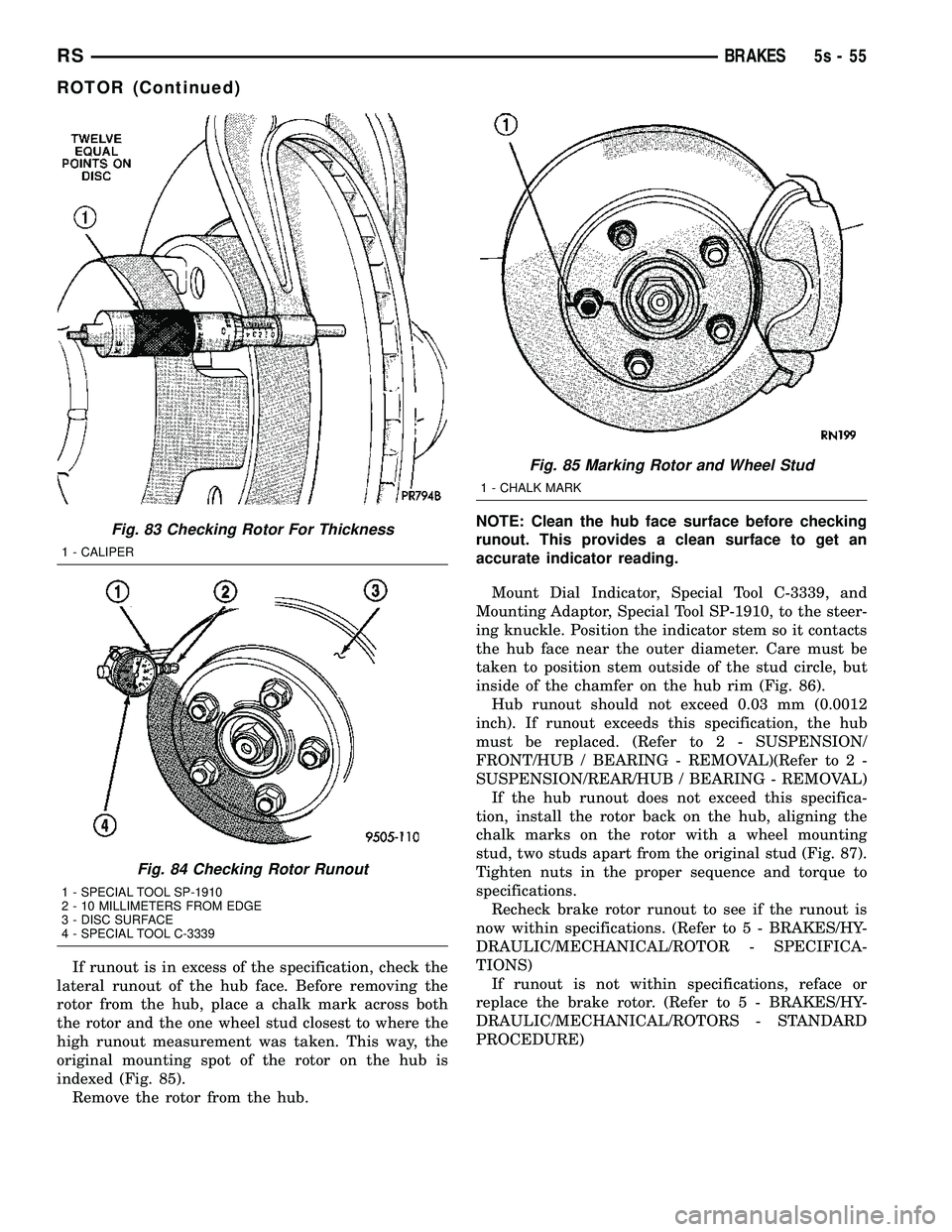
If runout is in excess of the specification, check the
lateral runout of the hub face. Before removing the
rotor from the hub, place a chalk mark across both
the rotor and the one wheel stud closest to where the
high runout measurement was taken. This way, the
original mounting spot of the rotor on the hub is
indexed (Fig. 85). Remove the rotor from the hub. NOTE: Clean the hub face surface before checking
runout. This provides a clean surface to get an
accurate indicator reading.
Mount Dial Indicator, Special Tool C-3339, and
Mounting Adaptor, Special Tool SP-1910, to the steer-
ing knuckle. Position the indicator stem so it contacts
the hub face near the outer diameter. Care must be
taken to position stem outside of the stud circle, but
inside of the chamfer on the hub rim (Fig. 86). Hub runout should not exceed 0.03 mm (0.0012
inch). If runout exceeds this specification, the hub
must be replaced. (Refer t o 2 - SUSPENSION/
FRONT/HUB / BEARING - REMOVAL)(Refer to 2 -
SUSPENSION/REAR/HUB / BEARING - REMOVAL) If the hub runout does not exceed this specifica-
tion, install the rotor back on the hub, aligning the
chalk marks on the rotor with a wheel mounting
stud, two studs apart from the original stud (Fig. 87).
Tighten nuts in the proper sequence and torque to
specifications. Recheck brake rotor runout to see if the runout is
now within specifications. (Refer t o 5 - BRAKES/HY-
DRAULIC/MECHANICAL/ROTOR - SPECIFICA-
TIONS) If runout is not within specifications, reface or
replace the brake rotor. (Refer t o 5 - BRAKES/HY-
DRAULIC/MECHANICAL/ROTORS - STANDARD
PROCEDURE)
Fig. 83 Checking Rotor For Thickness
1 - CALIPER
Fig. 84 Checking Rotor Runout
1 - SPECIAL TOOL SP-1910
2 - 10 MILLIMETERS FROM EDGE
3 - DISC SURFACE
4 - SPECIAL TOOL C-3339
Fig. 85 Marking Rotor and Wheel Stud
1 - CHALK MARK
RS BRAKES5s-55
ROTOR (Continued)
Page 300 of 2585
Minimum allowable thickness is the minimum
thickness which the brake rotor machined surface
may be cut to.
CAUTION: Do not machine the rotor if it will cause
the rotor to fall below minimum thickness.
Before installation, verify the brake rotor face and
the hub adapters are free of any chips, rust, or con-
tamination. When mounting and using the brake lathe, strict
attention to the brake lathe manufacturer's operating
instructions is required. Machine both sides of the brake rotor at the same
time. Cutting both sides at the same time minimizes
the possibility of a tapered or uneven cut. When refacing a rotor, the required TIR (Total
Indicator Reading) and thickness variation limits
MUST BE MAINTAINED. Extreme care in the oper-
ation of rotor turning equipment is required. Specifi-
cations for brake rotor machining can be found in
this section's specification table. (Refer to 5 -
BRAKES/HYDRAULIC/MECHANICAL/ROTOR -
SPECIFICATIONS)
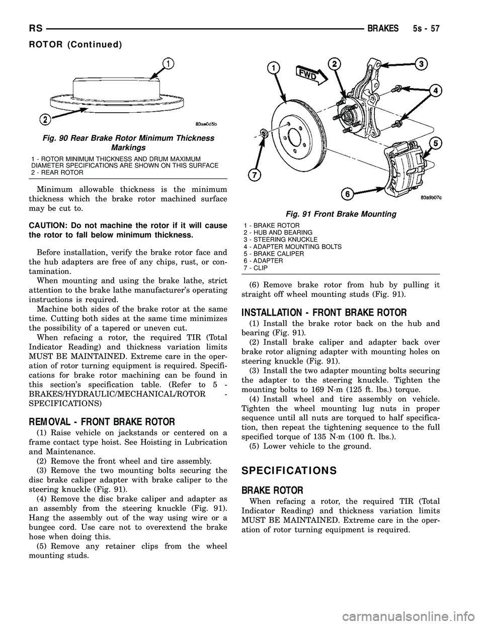
REMOVAL - FRONT BRAKE ROTOR
(1) Raise vehicle on jackstands or centered on a
frame contact type hoist. See Hoisting in Lubrication
and Maintenance. (2) Remove the front wheel and tire assembly.
(3) Remove the two mounting bolts securing the
disc brake caliper adapter with brake caliper to the
steering knuckle (Fig. 91). (4) Remove the disc brake caliper and adapter as
an assembly from the steering knuckle (Fig. 91).
Hang the assembly out of the way using wire or a
bungee cord. Use care not to overextend the brake
hose when doing this. (5) Remove any retainer clips from the wheel
mounting studs. (6) Remove brake rotor from hub by pulling it
straight off wheel mounting studs (Fig. 91).
INSTALLATION - FRONT BRAKE ROTOR
(1) Install the brake rotor back on the hub and
bearing (Fig. 91). (2) Install brake caliper and adapter back over
brake rotor aligning adapter with mounting holes on
steering knuckle (Fig. 91). (3) Install the two adapter mounting bolts securing
the adapter to the steering knuckle. Tighten the
mounting bolts to 169 N´m (125 ft. lbs.) torque. (4) Install wheel and tire assembly on vehicle.
Tighten the wheel mounting lug nuts in proper
sequence until all nuts are torqued to half specifica-
tion, then repeat the tightening sequence to the full
specified torque of 135 N´m (100 ft. lbs.). (5) Lower vehicle to the ground.
SPECIFICATIONS
BRAKE ROTOR
When refacing a rotor, the required TIR (Total
Indicator Reading) and thickness variation limits
MUST BE MAINTAINED. Extreme care in the oper-
ation of rotor turning equipment is required.
Fig. 90 Rear Brake Rotor Minimum Thickness Markings
1 - ROTOR MINIMUM THICKNESS AND DRUM MAXIMUM
DIAMETER SPECIFICATIONS ARE SHOWN ON THIS SURFACE
2 - REAR ROTOR
Fig. 91 Front Brake Mounting
1 - BRAKE ROTOR
2 - HUB AND BEARING
3 - STEERING KNUCKLE
4 - ADAPTER MOUNTING BOLTS
5 - BRAKE CALIPER
6 - ADAPTER
7 - CLIP
RS BRAKES5s-57
ROTOR (Continued)
Page 302 of 2585

(3) Install the rear hub and bearing (and connect
wheel speed sensor where applicable) stopping short
of installing the brake drum. (Refer t o 2 - SUSPEN-
SION/REAR/HUB / BEARING - INSTALLATION) (4) Install the rear park brake cable into its
mounting hole in the rear brake support plate. (5) Install the park brake cable on the park brake
actuation lever. (6) Apply sealant such as Mopar Gasket-In-A-Tube
or equivalent around the wheel cylinder opening in
the brake support plate. (7) Install wheel cylinder onto brake support.
Install and tighten the wheel cylinder to brake sup- port plate attaching bolts to 8 N´m (75 in. lbs.)
torque.
(8) Install brake tube into wheel cylinder. Tighten
tube nut to a torque of 17 N´m (145 in. lbs.) torque. (9) Install the rear brake shoes on the brake sup-
port plate. (Refer t o 5 - BRAKES/HYDRAULIC/ME-
CHANICAL/BRAKE PADS/SHOES -
INSTALLATION). (10) Install brake drum.
(11) Install the wheel and tire assembly. Tighten
the wheel mounting nuts in proper sequence until all
nuts are torqued to half specification, then repeat the
tightening sequence to the full specified torque of 135
N´m (100 ft. lbs.). (12) Adjust drum brake shoes. (Refer to 5 -
BRAKES/HYDRAULIC/MECHANICAL/BRAKE
PADS/SHOES - ADJUSTMENTS) (13) Remove brake pedal depressor tool.
(14) Bleed the brake system as necessary. (Refer to
5 - BRAKES - BASE - STANDARD PROCEDURE). (15) Lower the vehicle.
WHEEL CYLINDERS
REMOVAL
(1) Using a brake pedal depressor, move and
secure brake pedal to a position past its first 1 inch
of travel. This will prevent brake fluid from draining
out of master cylinder when brake tube is remove
from wheel cylinder. (2) Raise vehicle. (Refer to LUBRICATION &
MAINTENANCE/HOISTING - STANDARD PROCE-
DURE). (3) Remove wheel and tire assembly.
(4) Disconnect brake tube from rear of wheel cylin-
der. Cap open ends (5) Remove brake drum.
(6) Remove brake shoes from brake support plate
(Discard if contaminated).(Refer t o 5 - BRAKES/HY-
DRAULIC/MECHANICAL/BRAKE PADS/SHOES -
REMOVAL) (7) Remove the 2 bolts attaching the wheel cylin-
der to the brake support plate. (8) Remove the wheel cylinder from the brake sup-
port plate.
INSPECTION
With brake drums removed, inspect the wheel cyl-
inder boots for evidence of a brake fluid leak. Visu-
ally check the boots for cuts, tears, or heat cracks. If
any of these conditions exist, the wheel cylinders
should be completely cleaned, inspected and new
parts installed.
Fig. 92 Removing Park Brake Cable From Brake Support Plate
1 - PARK BRAKE CABLE
2 - CABLE RETAINER
3 - 14 mm BOX WRENCH
4 - BRAKE SUPPORT PLATE
Fig. 93 Brake Support Plate Mounted On BearingAttaching Bolts
1 - REAR BRAKE SUPPORT PLATE
2 - HUB/BEARING MOUNTING BOLTS
RS BRAKES5s-59
SUPPORT PLATE - DRUM BRAKE (Continued)