oxygen CHRYSLER VOYAGER 2004 User Guide
[x] Cancel search | Manufacturer: CHRYSLER, Model Year: 2004, Model line: VOYAGER, Model: CHRYSLER VOYAGER 2004Pages: 2585, PDF Size: 62.54 MB
Page 1099 of 2585
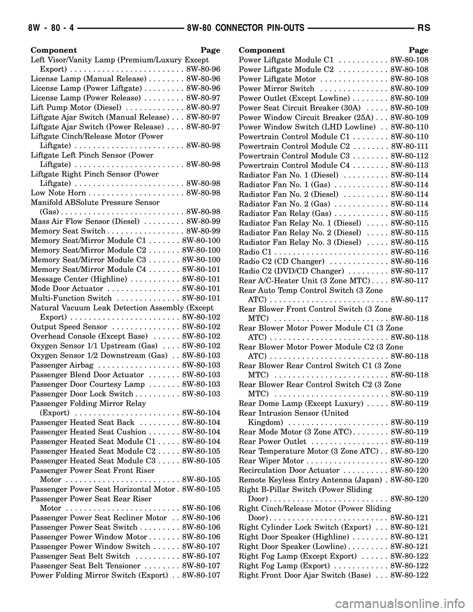
Component Page
Left Visor/Vanity Lamp (Premium/Luxury Except
Export)......................... 8W-80-96
License Lamp (Manual Release)........ 8W-80-96
License Lamp (Power Liftgate)......... 8W-80-96
License Lamp (Power Release)......... 8W-80-97
Lift Pump Motor (Diesel)............. 8W-80-97
Liftgate Ajar Switch (Manual Release) . . . 8W-80-97
Liftgate Ajar Switch (Power Release).... 8W-80-97
Liftgate Cinch/Release Motor (Power
Liftgate)........................ 8W-80-98
Liftgate Left Pinch Sensor (Power
Liftgate)........................ 8W-80-98
Liftgate Right Pinch Sensor (Power
Liftgate)........................ 8W-80-98
Low Note Horn..................... 8W-80-98
Manifold ABSolute Pressure Sensor
(Gas)........................... 8W-80-98
Mass Air Flow Sensor (Diesel)......... 8W-80-99
Memory Seat Switch................. 8W-80-99
Memory Seat/Mirror Module C1....... 8W-80-100
Memory Seat/Mirror Module C2....... 8W-80-100
Memory Seat/Mirror Module C3....... 8W-80-100
Memory Seat/Mirror Module C4....... 8W-80-101
Message Center (Highline)........... 8W-80-101
Mode Door Actuator................ 8W-80-101
Multi-Function Switch.............. 8W-80-101
Natural Vacuum Leak Detection Assembly (Except
Export)........................ 8W-80-102
Output Speed Sensor............... 8W-80-102
Overhead Console (Except Base)...... 8W-80-102
Oxygen Sensor 1/1 Upstream (Gas).... 8W-80-102
Oxygen Sensor 1/2 Downstream (Gas) . . 8W-80-103
Passenger Airbag.................. 8W-80-103
Passenger Blend Door Actuator....... 8W-80-103
Passenger Door Courtesy Lamp....... 8W-80-103
Passenger Door Lock Switch.......... 8W-80-103
Passenger Folding Mirror Relay
(Export)....................... 8W-80-104
Passenger Heated Seat Back......... 8W-80-104
Passenger Heated Seat Cushion....... 8W-80-104
Passenger Heated Seat Module C1..... 8W-80-104
Passenger Heated Seat Module C2..... 8W-80-105
Passenger Heated Seat Module C3..... 8W-80-105
Passenger Power Seat Front Riser
Motor......................... 8W-80-105
Passenger Power Seat Horizontal Motor . 8W-80-105
Passenger Power Seat Rear Riser
Motor......................... 8W-80-106
Passenger Power Seat Recliner Motor . . 8W-80-106
Passenger Power Seat Switch......... 8W-80-106
Passenger Power Window Motor....... 8W-80-106
Passenger Power Window Switch...... 8W-80-107
Passenger Seat Belt Switch.......... 8W-80-107
Passenger Seat Belt Tensioner........ 8W-80-107
Power Folding Mirror Switch (Export) . . 8W-80-107Component Page
Power Liftgate Module C1........... 8W-80-108
Power Liftgate Module C2........... 8W-80-108
Power Liftgate Motor............... 8W-80-108
Power Mirror Switch............... 8W-80-109
Power Outlet (Except Lowline)........ 8W-80-109
Power Seat Circuit Breaker (30A)..... 8W-80-109
Power Window Circuit Breaker (25A) . . . 8W-80-109
Power Window Switch (LHD Lowline) . . 8W-80-110
Powertrain Control Module C1........ 8W-80-110
Powertrain Control Module C2........ 8W-80-111
Powertrain Control Module C3........ 8W-80-112
Powertrain Control Module C4........ 8W-80-113
Radiator Fan No. 1 (Diesel).......... 8W-80-114
Radiator Fan No. 1 (Gas)............ 8W-80-114
Radiator Fan No. 2 (Diesel).......... 8W-80-114
Radiator Fan No. 2 (Gas)............ 8W-80-114
Radiator Fan Relay (Gas)............ 8W-80-115
Radiator Fan Relay No. 1 (Diesel)..... 8W-80-115
Radiator Fan Relay No. 2 (Diesel)..... 8W-80-115
Radiator Fan Relay No. 3 (Diesel)..... 8W-80-115
Radio C1......................... 8W-80-116
Radio C2 (CD Changer)............. 8W-80-116
Radio C2 (DVD/CD Changer)......... 8W-80-117
Rear A/C-Heater Unit (3 Zone MTC).... 8W-80-117
Rear Auto Temp Control Switch (3 Zone
ATC) .......................... 8W-80-117
Rear Blower Front Control Switch (3 Zone
MTC)......................... 8W-80-118
Rear Blower Motor Power Module C1 (3 Zone
ATC) .......................... 8W-80-118
Rear Blower Motor Power Module C2 (3 Zone
ATC) .......................... 8W-80-118
Rear Blower Rear Control Switch C1 (3 Zone
MTC)......................... 8W-80-118
Rear Blower Rear Control Switch C2 (3 Zone
MTC)......................... 8W-80-119
Rear Dome Lamp (Except Luxury)..... 8W-80-119
Rear Intrusion Sensor (United
Kingdom)...................... 8W-80-119
Rear Mode Motor (3 Zone ATC)........ 8W-80-119
Rear Power Outlet................. 8W-80-119
Rear Temperature Motor (3 Zone ATC) . . 8W-80-120
Rear Wiper Motor.................. 8W-80-120
Recirculation Door Actuator.......... 8W-80-120
Remote Keyless Entry Antenna (Japan) . 8W-80-120
Right B-Pillar Switch (Power Sliding
Door).......................... 8W-80-120
Right Cinch/Release Motor (Power Sliding
Door).......................... 8W-80-121
Right Cylinder Lock Switch (Export) . . . 8W-80-121
Right Door Speaker (Highline)........ 8W-80-121
Right Door Speaker (Lowline)......... 8W-80-121
Right Fog Lamp (Except Export)...... 8W-80-122
Right Fog Lamp (Export)............ 8W-80-122
Right Front Door Ajar Switch (Base) . . . 8W-80-122
8W - 80 - 4 8W-80 CONNECTOR PIN-OUTSRS
Page 1197 of 2585
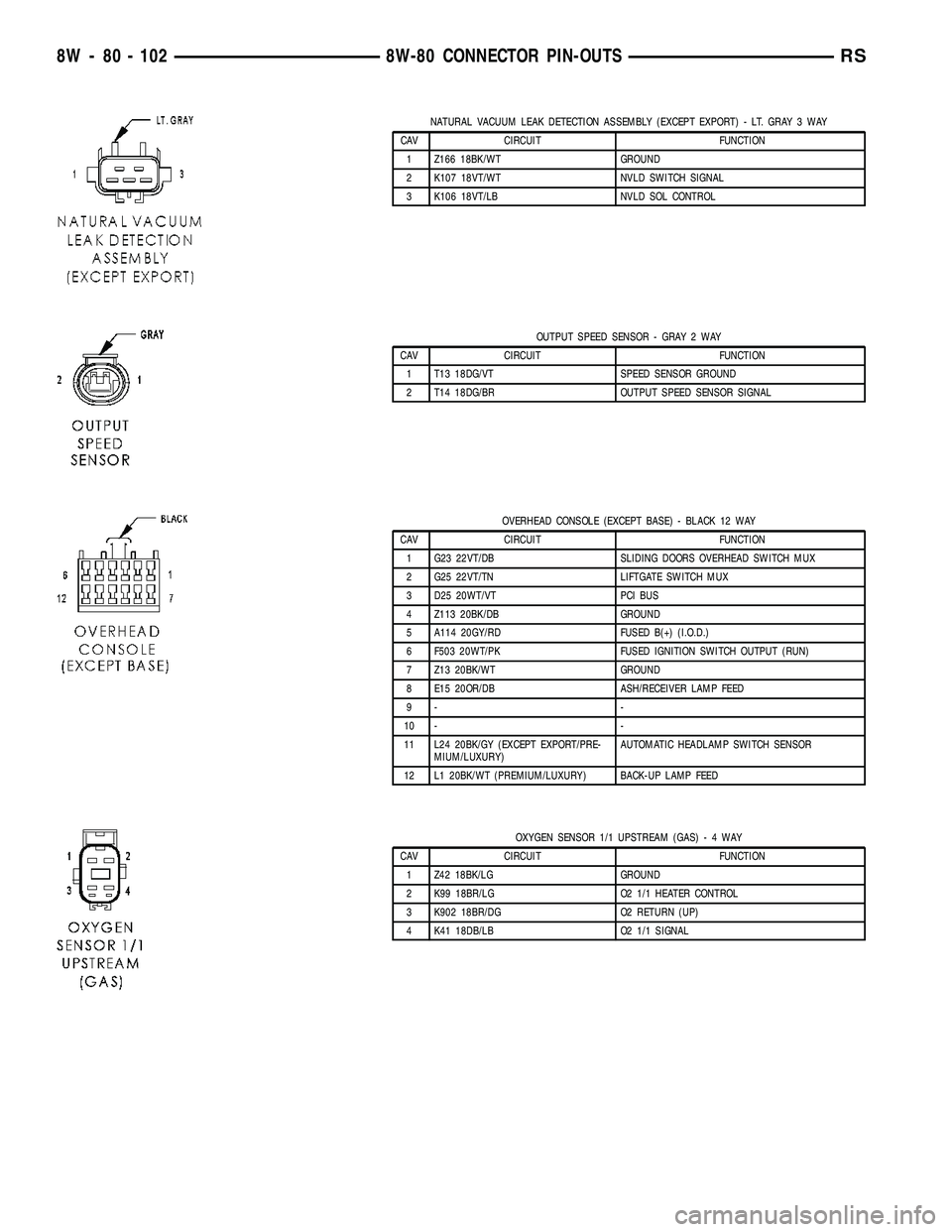
NATURAL VACUUM LEAK DETECTION ASSEMBLY (EXCEPT EXPORT) - LT. GRAY 3 WAY
CAV CIRCUIT FUNCTION
1 Z166 18BK/WT GROUND
2 K107 18VT/WT NVLD SWITCH SIGNAL
3 K106 18VT/LB NVLD SOL CONTROL
OUTPUT SPEED SENSOR - GRAY 2 WAY
CAV CIRCUIT FUNCTION
1 T13 18DG/VT SPEED SENSOR GROUND
2 T14 18DG/BR OUTPUT SPEED SENSOR SIGNAL
OVERHEAD CONSOLE (EXCEPT BASE) - BLACK 12 WAY
CAV CIRCUIT FUNCTION
1 G23 22VT/DB SLIDING DOORS OVERHEAD SWITCH MUX
2 G25 22VT/TN LIFTGATE SWITCH MUX
3 D25 20WT/VT PCI BUS
4 Z113 20BK/DB GROUND
5 A114 20GY/RD FUSED B(+) (I.O.D.)
6 F503 20WT/PK FUSED IGNITION SWITCH OUTPUT (RUN)
7 Z13 20BK/WT GROUND
8 E15 20OR/DB ASH/RECEIVER LAMP FEED
9- -
10 - -
11 L24 20BK/GY (EXCEPT EXPORT/PRE-
MIUM/LUXURY)AUTOMATIC HEADLAMP SWITCH SENSOR
12 L1 20BK/WT (PREMIUM/LUXURY) BACK-UP LAMP FEED
OXYGEN SENSOR 1/1 UPSTREAM (GAS)-4WAY
CAV CIRCUIT FUNCTION
1 Z42 18BK/LG GROUND
2 K99 18BR/LG O2 1/1 HEATER CONTROL
3 K902 18BR/DG O2 RETURN (UP)
4 K41 18DB/LB O2 1/1 SIGNAL
8W - 80 - 102 8W-80 CONNECTOR PIN-OUTSRS
Page 1198 of 2585
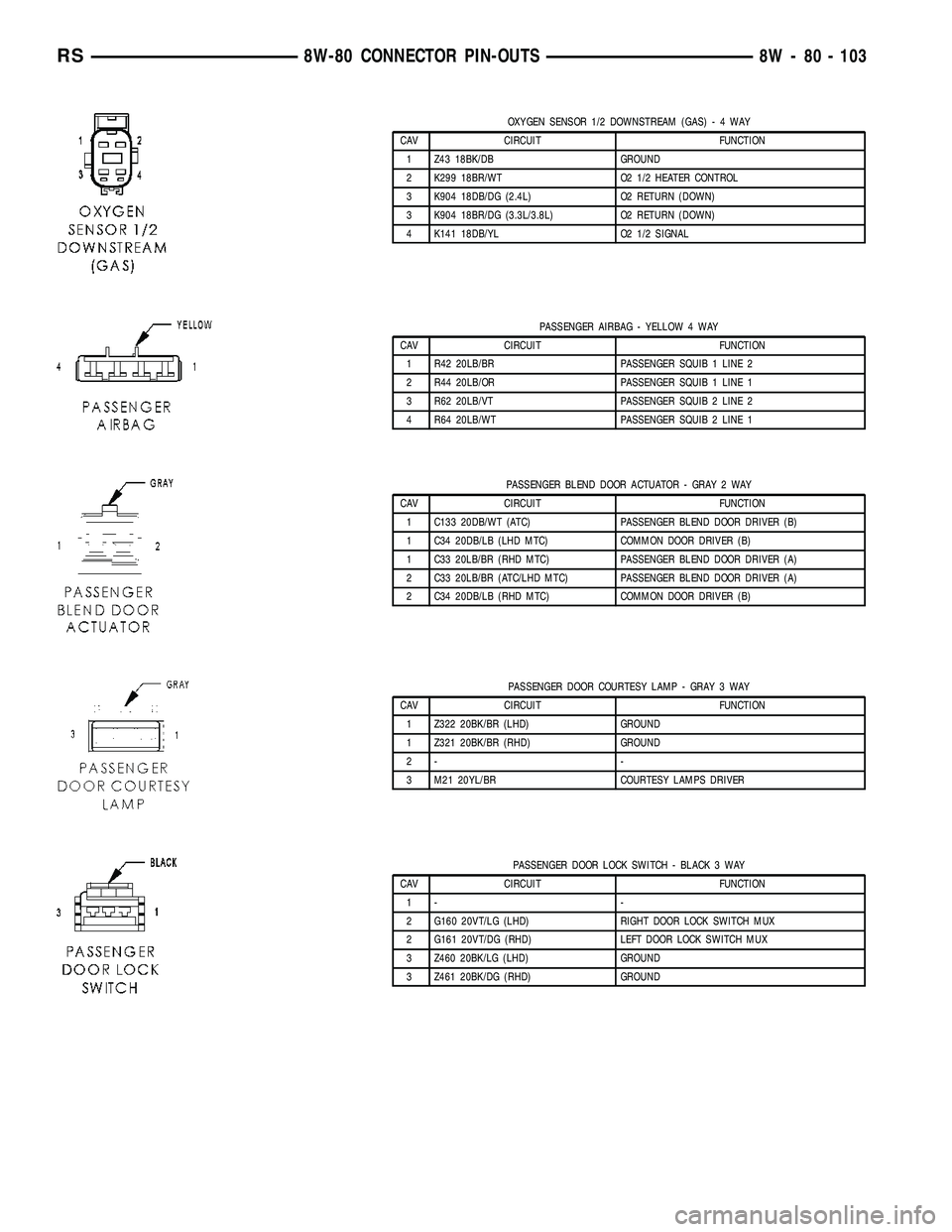
OXYGEN SENSOR 1/2 DOWNSTREAM (GAS)-4WAY
CAV CIRCUIT FUNCTION
1 Z43 18BK/DB GROUND
2 K299 18BR/WT O2 1/2 HEATER CONTROL
3 K904 18DB/DG (2.4L) O2 RETURN (DOWN)
3 K904 18BR/DG (3.3L/3.8L) O2 RETURN (DOWN)
4 K141 18DB/YL O2 1/2 SIGNAL
PASSENGER AIRBAG - YELLOW 4 WAY
CAV CIRCUIT FUNCTION
1 R42 20LB/BR PASSENGER SQUIB 1 LINE 2
2 R44 20LB/OR PASSENGER SQUIB 1 LINE 1
3 R62 20LB/VT PASSENGER SQUIB 2 LINE 2
4 R64 20LB/WT PASSENGER SQUIB 2 LINE 1
PASSENGER BLEND DOOR ACTUATOR - GRAY 2 WAY
CAV CIRCUIT FUNCTION
1 C133 20DB/WT (ATC) PASSENGER BLEND DOOR DRIVER (B)
1 C34 20DB/LB (LHD MTC) COMMON DOOR DRIVER (B)
1 C33 20LB/BR (RHD MTC) PASSENGER BLEND DOOR DRIVER (A)
2 C33 20LB/BR (ATC/LHD MTC) PASSENGER BLEND DOOR DRIVER (A)
2 C34 20DB/LB (RHD MTC) COMMON DOOR DRIVER (B)
PASSENGER DOOR COURTESY LAMP - GRAY 3 WAY
CAV CIRCUIT FUNCTION
1 Z322 20BK/BR (LHD) GROUND
1 Z321 20BK/BR (RHD) GROUND
2- -
3 M21 20YL/BR COURTESY LAMPS DRIVER
PASSENGER DOOR LOCK SWITCH - BLACK 3 WAY
CAV CIRCUIT FUNCTION
1- -
2 G160 20VT/LG (LHD) RIGHT DOOR LOCK SWITCH MUX
2 G161 20VT/DG (RHD) LEFT DOOR LOCK SWITCH MUX
3 Z460 20BK/LG (LHD) GROUND
3 Z461 20BK/DG (RHD) GROUND
RS8W-80 CONNECTOR PIN-OUTS8W - 80 - 103
Page 1239 of 2585
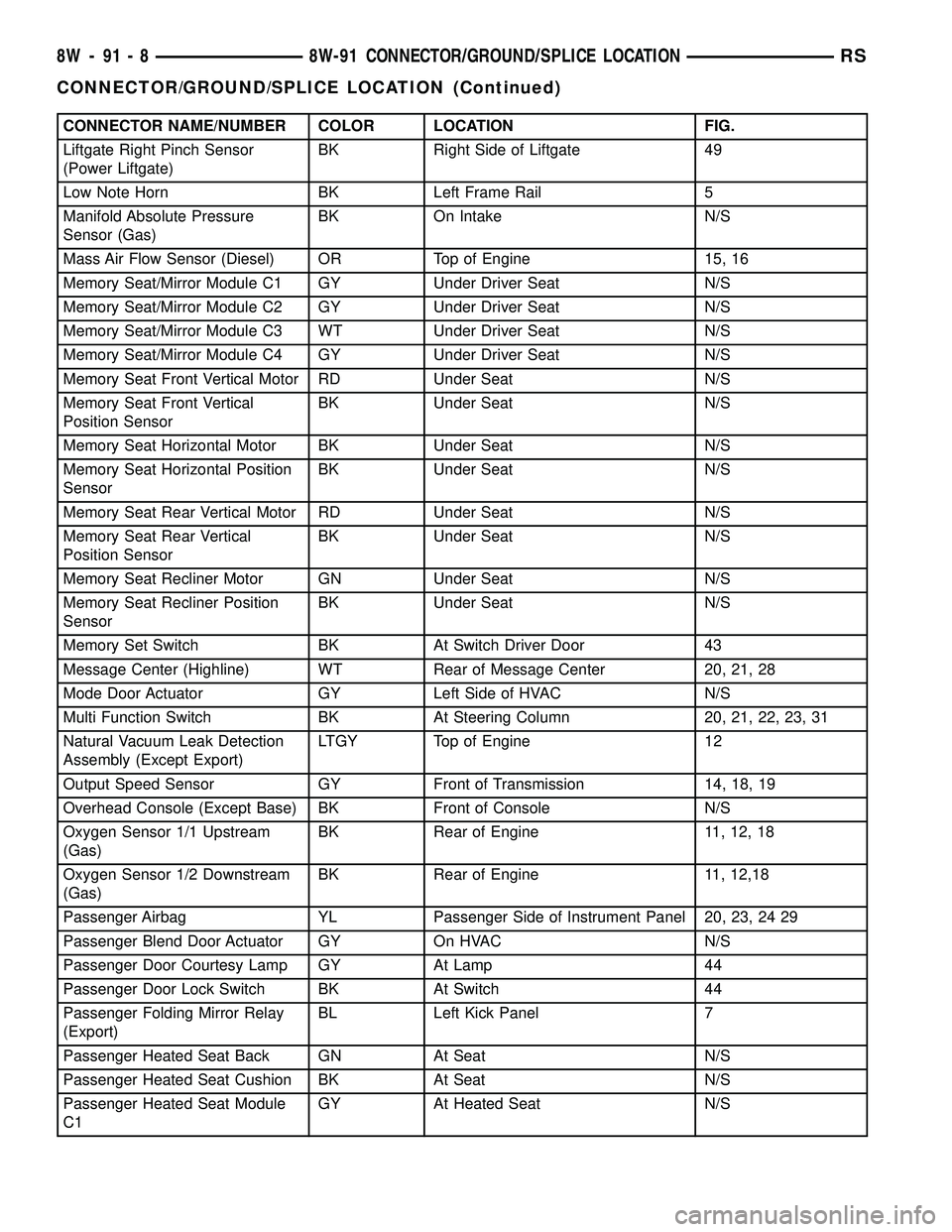
CONNECTOR NAME/NUMBER COLOR LOCATION FIG.
Liftgate Right Pinch Sensor
(Power Liftgate)BK Right Side of Liftgate 49
Low Note Horn BK Left Frame Rail 5
Manifold Absolute Pressure
Sensor (Gas)BK On Intake N/S
Mass Air Flow Sensor (Diesel) OR Top of Engine 15, 16
Memory Seat/Mirror Module C1 GY Under Driver Seat N/S
Memory Seat/Mirror Module C2 GY Under Driver Seat N/S
Memory Seat/Mirror Module C3 WT Under Driver Seat N/S
Memory Seat/Mirror Module C4 GY Under Driver Seat N/S
Memory Seat Front Vertical Motor RD Under Seat N/S
Memory Seat Front Vertical
Position SensorBK Under Seat N/S
Memory Seat Horizontal Motor BK Under Seat N/S
Memory Seat Horizontal Position
SensorBK Under Seat N/S
Memory Seat Rear Vertical Motor RD Under Seat N/S
Memory Seat Rear Vertical
Position SensorBK Under Seat N/S
Memory Seat Recliner Motor GN Under Seat N/S
Memory Seat Recliner Position
SensorBK Under Seat N/S
Memory Set Switch BK At Switch Driver Door 43
Message Center (Highline) WT Rear of Message Center 20, 21, 28
Mode Door Actuator GY Left Side of HVAC N/S
Multi Function Switch BK At Steering Column 20, 21, 22, 23, 31
Natural Vacuum Leak Detection
Assembly (Except Export)LTGY Top of Engine 12
Output Speed Sensor GY Front of Transmission 14, 18, 19
Overhead Console (Except Base) BK Front of Console N/S
Oxygen Sensor 1/1 Upstream
(Gas)BK Rear of Engine 11, 12, 18
Oxygen Sensor 1/2 Downstream
(Gas)BK Rear of Engine 11, 12,18
Passenger Airbag YL Passenger Side of Instrument Panel 20, 23, 24 29
Passenger Blend Door Actuator GY On HVAC N/S
Passenger Door Courtesy Lamp GY At Lamp 44
Passenger Door Lock Switch BK At Switch 44
Passenger Folding Mirror Relay
(Export)BL Left Kick Panel 7
Passenger Heated Seat Back GN At Seat N/S
Passenger Heated Seat Cushion BK At Seat N/S
Passenger Heated Seat Module
C1GY At Heated Seat N/S
8W - 91 - 8 8W-91 CONNECTOR/GROUND/SPLICE LOCATIONRS
CONNECTOR/GROUND/SPLICE LOCATION (Continued)
Page 1258 of 2585
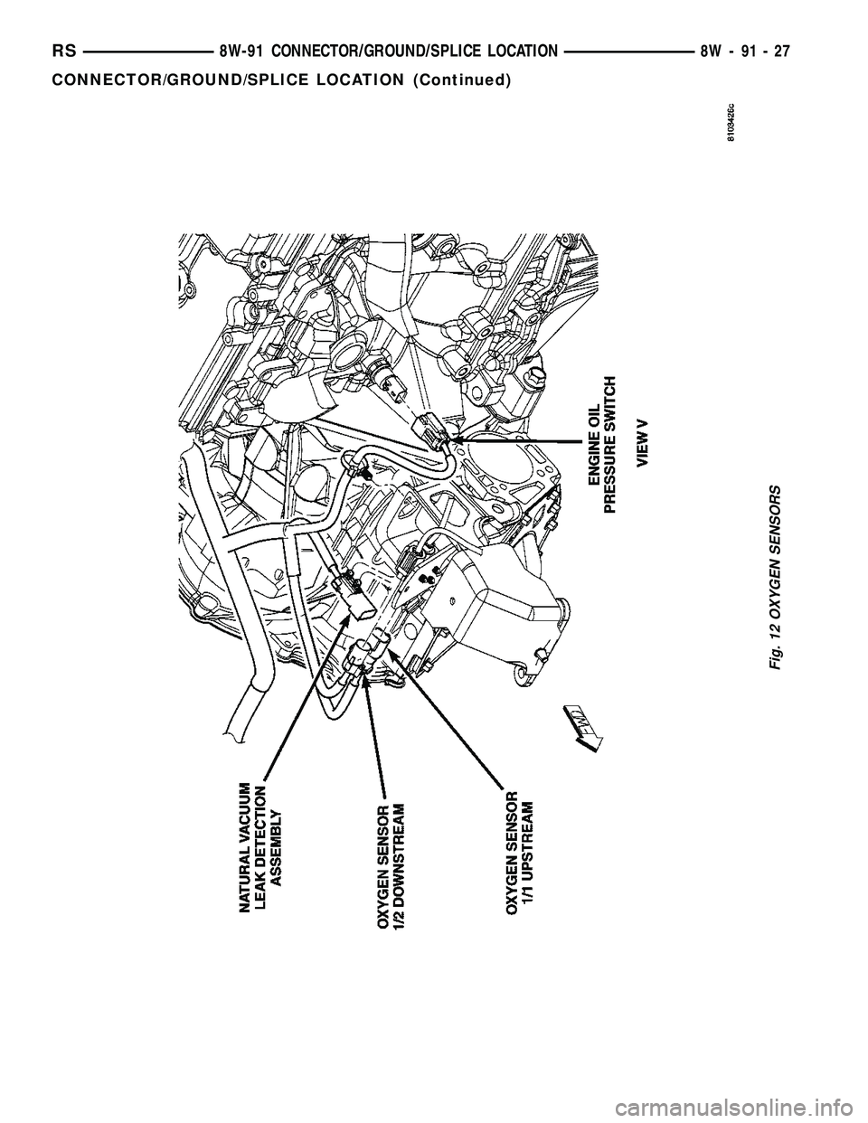
Fig. 12 OXYGEN SENSORS
RS8W-91 CONNECTOR/GROUND/SPLICE LOCATION8W-91-27
CONNECTOR/GROUND/SPLICE LOCATION (Continued)
Page 1358 of 2585

EXHAUST MANIFOLD
REMOVAL
(1) Raise vehicle and disconnect exhaust pipe from
the exhaust manifold.
(2) Disconnect upstream oxygen sensor connector
at the rear of exhaust manifold.
(3) Remove the bolts attaching the manifold to the
cylinder head.
(4) Remove exhaust manifold.
(5) Inspect the manifold. (Refer to 9 - ENGINE/
MANIFOLDS/EXHAUST MANIFOLD - INSPEC-
TION)
CLEANING
(1) Discard gasket (if equipped) and clean all sur-
faces of manifold and cylinder head.
INSPECTION
(1) Inspect manifold gasket surfaces for flatness
with straight edge. Surface must be flat within 0.15
mm per 300 mm (0.006 in. per foot) of manifold
length.
(2) Inspect manifolds for cracks or distortion.
Replace manifold as necessary.
INSTALLATION
(1) Install exhaust manifold with a new gasket.
Tighten attaching nuts in the sequence shown in
(Fig. 109) to 19 N´m (170 in. lbs.).
(2) Attach exhaust pipe to exhaust manifold and
tighten fasteners to 37 N´m (27 ft. lbs.).
(3) Install and connect the oxygen sensor. (Refer to
14 - FUEL SYSTEM/FUEL INJECTION/O2 SENSOR
- COMPONENT LOCATION)
TIMING BELT COVER(S)
REMOVAL
FRONT COVER - UPPER
(1) Remove upper timing belt cover fasteners (Fig.
110) and remove cover.
FRONT COVER - LOWER
(1) Remove crankshaft vibration damper (Refer to
9 - ENGINE/ENGINE BLOCK/VIBRATION
DAMPER - REMOVAL).
(2) Remove generator drive belt tensioner assem-
bly (Refer to 7 - COOLING/ACCESSORY DRIVE/
BELT TENSIONERS - REMOVAL).
(3) Remove timing belt front cover bolts (Fig. 110)
and remove covers.
REAR COVER
(1) Remove front covers.
(2) Remove engine mount bracket (Fig. 111).
(3) Remove timing belt (Refer to 9 - ENGINE/
VALVE TIMING/TIMING BELT AND SPROCKETS -
REMOVAL).
Fig. 109 Exhaust Manifold Tightening Sequence
Fig. 110 Front Timing Belt Covers
1 - BOLTS - UPPER FRONT COVER 6 N´m (50 in. lbs.)
2 - BOLTS - LOWER FRONT COVER 6 N´m (50 in. lbs.)
RSENGINE 2.4L9-61
Page 1447 of 2585

(11) Fill the cooling system. (Refer to 7 - COOL-
ING - STANDARD PROCEDURE)
EXHAUST MANIFOLD - RIGHT
REMOVAL
(1) Disconnect battery negative cable.
(2) Remove the wiper module. (Refer to 8 - ELEC-
TRICAL/WIPERS/WASHERS/WIPER MODULE -
REMOVAL)
(3) Disconnect spark plug wires.
(4) Remove bolts fastening crossover pipe to
exhaust manifold (Fig. 124).
(5) Disconnect and remove the upstream oxygen
sensor (Fig. 127).(6) Remove the heat shield attaching screws (Fig.
127).
(7) Remove the upper heat shield (Fig. 127).
(8) Raise vehicle on hoist and remove drive belt
shield.
(9) Loosen the power steering pump support strut
lower bolt (Fig. 125).
(10) Disconnect downstream oxygen sensor connec-
tor.
(11) Disconnect catalytic converter pipe from
exhaust manifold (Fig. 126).
Fig. 123 LOWER MANIFOLD TIGHTENING
SEQUENCE
Fig. 124 CROSS-OVER PIPE
1 - CROSS-OVER PIPE
2 - BOLT
3 - GASKET
4 - FLAG NUT
Fig. 125 P/S PUMP STRUT
1 - BOLT - LOWER
2 - STRUT - P/S PUMP
3 - BOLT - UPPER
Fig. 126 Catalytic Converter to Exhaust Manifold
1 - FLAG NUT
2 - GASKET
3 - BOLT
4 - CATALYTIC CONVERTER
9 - 150 ENGINE 3.3/3.8LRS
INTAKE MANIFOLD - LOWER (Continued)
Page 1448 of 2585

(12) Lower vehicle and remove the power steering
pump support strut upper bolt (Fig. 125).
(13) Remove bolts attaching exhaust manifold to
cylinder head and remove manifold (Fig. 127).
(14) Inspect and clean manifold. (Refer to 9 -
ENGINE/MANIFOLDS/EXHAUST MANIFOLD -
CLEANING) (Refer to 9 - ENGINE/MANIFOLDS/
EXHAUST MANIFOLD - INSPECTION)
CLEANING
(1) Discard gasket (if equipped) and clean all sur-
faces of manifold and cylinder head.
INSPECTION
Inspect exhaust manifolds for damage or cracks
and check distortion of the cylinder head mounting
surface and exhaust crossover mounting surface with
a straightedge and thickness gauge (Fig. 128).
Manifold surface flatness limits should not exceed
1.0 mm (0.039 in.).
INSTALLATION
(1) Position exhaust manifold on cylinder head and
install bolts to center runner (cylinder #3) and initial
tighten to 2.8 N´m (25 in. lbs.) (Fig. 127)
(2) Using a new gasket, attach crossover pipe to
exhaust manifold and tighten bolts to 41 N´m (30 ft.
lbs.) (Fig. 124).NOTE: Inspect crossover pipe fasteners for damage
from heat and corrosion. The cross-over bolts are
made of a special stainless steel alloy. If replace-
ment is required, OEM bolts are highly recom-
mended.
(3) Install the remaining manifold attaching bolts.
Tighten all bolts to 23 N´m (200 in. lbs.).
(4) Position the power steering pump support strut
and install upper bolt (Fig. 125).
(5) Install heat shield and attaching screws (Fig.
127).
(6) Install and connect upstream oxygen sensor
(Fig. 127).
(7) Raise the vehicle.
(8) Attach catalytic converter pipe to exhaust man-
ifold using new gasket and tighten bolts to 37 N´m
(27 ft. lbs.) (Fig. 126).
(9) Connect downstream oxygen sensor connector.
(10) Tighten the power steering pump support
strut lower bolt (Fig. 125).
(11) Install the belt splash shield and lower the
vehicle.
(12) Install the wiper module. (Refer to 8 - ELEC-
TRICAL/WIPERS/WASHERS/WIPER MODULE -
INSTALLATION)
(13) Connect battery negative cable.
Fig. 127 EXHAUST MANIFOLD - RIGHT
1 - SCREW - HEAT SHIELD
2 - HEAT SHIELD - UPPER
3 - BOLT - EXHAUST MANIFOLD
4 - HEAT SHIELD - LOWER
5 - EXHAUST MANIFOLD - RIGHT
6 - OXYGEN SENSOR - UPSTREAM
Fig. 128 Check Exhaust Manifold Mounting
1 - STRAIGHT EDGE
2 - CROSSOVER PIPE MOUNTING SURFACE
3 - FEELER GAUGE
RSENGINE 3.3/3.8L9 - 151
EXHAUST MANIFOLD - RIGHT (Continued)
Page 1487 of 2585
DIAGNOSIS AND TESTING
DIAGNOSIS AND TESTING - EXCESSIVE
EXHAUST SYSTEM NOISE
CONDITION POSSIBLE CAUSES CORRECTION
EXCESSIVE EXHAUST NOISE
(UNDER HOOD)1. Exhaust manifold cracked or
broken.1. Replace manifold.
2. Manifold to cylinder head leak. 2. Tighten manifold and/or replace
gasket.
3. EGR Valve to manifold gasket
leakage.3. Tighten fasteners or replace
gasket.
4. EGR Valve to EGR tube gasket
leakage.4. Tighten fasteners or replace
gasket.
5. EGR tube to manifold tube
leakage.5. Tighten tube nut.
6. Exhaust flex-joint to manifold
leak.6. Tighten joint fasteners and/or
replace gasket.
7. Exhaust flex-joint. 7. Replace catalytic converter
assembly.
8. Pipe and shell noise from front
exhaust pipe.8. Characteristic of single wall pipe.
EXCESSIVE EXHAUST NOISE 1. Leak at exhaust pipe joints. 1. Tighten clamps at leaking joints.
2. Burned or rusted out muffler
assembly or exhaust pipe.2. Replace muffler resonator tailpipe
assembly or exhaust pipe with
catalytic converter assembly.
3. Burned or rusted out resonator. 3. Replace muffler resonator tailpipe
assembly.
4. Restriction in exhaust system. 4. Perform Exhaust System
Restriction Check. Replace
component as necessary.
5. Converter material in muffler. 5. Replace muffler and converter
assemblies. Check fuel injection and
ignition systems for proper
operation.
DIAGNOSIS AND TESTING - EXHAUST SYSTEM
RESTRICTION CHECK
Exhaust system restriction can be checked by mea-
suring back pressure using the DRB IIItand PEP
module pressure tester.
WARNING: THE NORMAL OPERATING TEMPERA-
TURE OF THE EXHAUST SYSTEM IS VERY HIGH.
THEREFORE, NEVER WORK AROUND OR ATTEMPT
TO SERVICE ANY PART OF THE EXHAUST SYSTEM
UNTIL IT IS COOLED. SPECIAL CARE SHOULD BE
TAKEN WHEN WORKING NEAR THE CATALYTIC
CONVERTER. THE TEMPERATURE OF THE CON-VERTER RISES TO A HIGH LEVEL AFTER A SHORT
PERIOD OF ENGINE OPERATION TIME.
NOTE: For Special Tool identification, (Refer to 11 -
EXHAUST SYSTEM - SPECIAL TOOLS).
(1) Disconnect and remove the upstream (before
catalytic converter) oxygen sensor. (Refer to 14 -
FUEL SYSTEM/FUEL INJECTION/O2 SENSOR -
REMOVAL)
(2) Install the Exhaust Back Pressure Fitting
Adaptor CH8519.
(3) Connect the Low Pressure Sensor (15 psi)
CH7063 to the back pressure fitting.
11 - 2 EXHAUST SYSTEMRS
EXHAUST SYSTEM (Continued)
Page 1489 of 2585
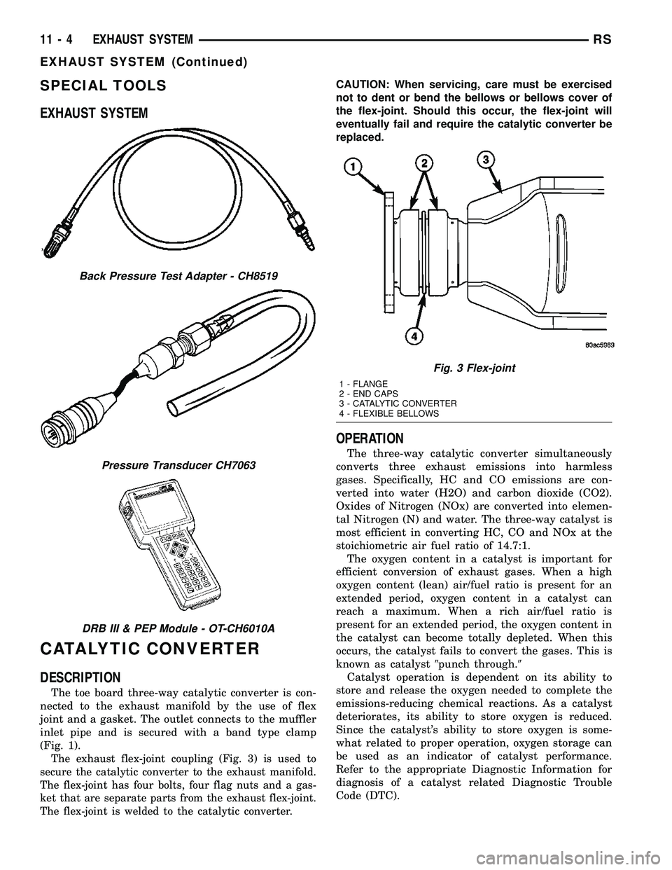
SPECIAL TOOLS
EXHAUST SYSTEM
CATALYTIC CONVERTER
DESCRIPTION
The toe board three-way catalytic converter is con-
nected to the exhaust manifold by the use of flex
joint and a gasket. The outlet connects to the muffler
inlet pipe and is secured with a band type clamp
(Fig. 1).
The exhaust flex-joint coupling (Fig. 3) is used to
secure the catalytic converter to the exhaust manifold.
The flex-joint has four bolts, four flag nuts and a gas-
ket that are separate parts from the exhaust flex-joint.
The flex-joint is welded to the catalytic converter.
CAUTION: When servicing, care must be exercised
not to dent or bend the bellows or bellows cover of
the flex-joint. Should this occur, the flex-joint will
eventually fail and require the catalytic converter be
replaced.
OPERATION
The three-way catalytic converter simultaneously
converts three exhaust emissions into harmless
gases. Specifically, HC and CO emissions are con-
verted into water (H2O) and carbon dioxide (CO2).
Oxides of Nitrogen (NOx) are converted into elemen-
tal Nitrogen (N) and water. The three-way catalyst is
most efficient in converting HC, CO and NOx at the
stoichiometric air fuel ratio of 14.7:1.
The oxygen content in a catalyst is important for
efficient conversion of exhaust gases. When a high
oxygen content (lean) air/fuel ratio is present for an
extended period, oxygen content in a catalyst can
reach a maximum. When a rich air/fuel ratio is
present for an extended period, the oxygen content in
the catalyst can become totally depleted. When this
occurs, the catalyst fails to convert the gases. This is
known as catalyst9punch through.9
Catalyst operation is dependent on its ability to
store and release the oxygen needed to complete the
emissions-reducing chemical reactions. As a catalyst
deteriorates, its ability to store oxygen is reduced.
Since the catalyst's ability to store oxygen is some-
what related to proper operation, oxygen storage can
be used as an indicator of catalyst performance.
Refer to the appropriate Diagnostic Information for
diagnosis of a catalyst related Diagnostic Trouble
Code (DTC).
Back Pressure Test Adapter - CH8519
Pressure Transducer CH7063
DRB III & PEP Module - OT-CH6010A
Fig. 3 Flex-joint
1 - FLANGE
2 - END CAPS
3 - CATALYTIC CONVERTER
4 - FLEXIBLE BELLOWS
11 - 4 EXHAUST SYSTEMRS
EXHAUST SYSTEM (Continued)