torque CHRYSLER VOYAGER 2004 Service Manual
[x] Cancel search | Manufacturer: CHRYSLER, Model Year: 2004, Model line: VOYAGER, Model: CHRYSLER VOYAGER 2004Pages: 2585, PDF Size: 62.54 MB
Page 1444 of 2585

²Mounting surface distortion by using a straight-
edge and thickness gauge.
INSTALLATION - UPPER INTAKE MANIFOLD
(1) If the following components were removed from
manifold, install and tighten to specifications:
CAUTION: The special screws used for the compos-
ite manifold attached components must be installed
slowly using hand tools only. This requirement is to
prevent the melting of material that causes stripped
threads. If threads become stripped, an oversize
repair screw is available. For more information and
procedure (Refer to 9 - ENGINE/MANIFOLDS/IN-
TAKE MANIFOLD - STANDARD PROCEDURE - MAN-
IFOLD STRIPPED THREAD REPAIR).
²MAP sensor - 1.7 N´m (15 in. lbs.)
²Throttle cable bracket - 5.6 N´m (50 in. lbs.)
(2) Remove covering on lower intake manifold and
clean surfaces.
(3) Inspect manifold gasket condition. Gaskets can
be re-used, if not damaged. To replace, remove gasket
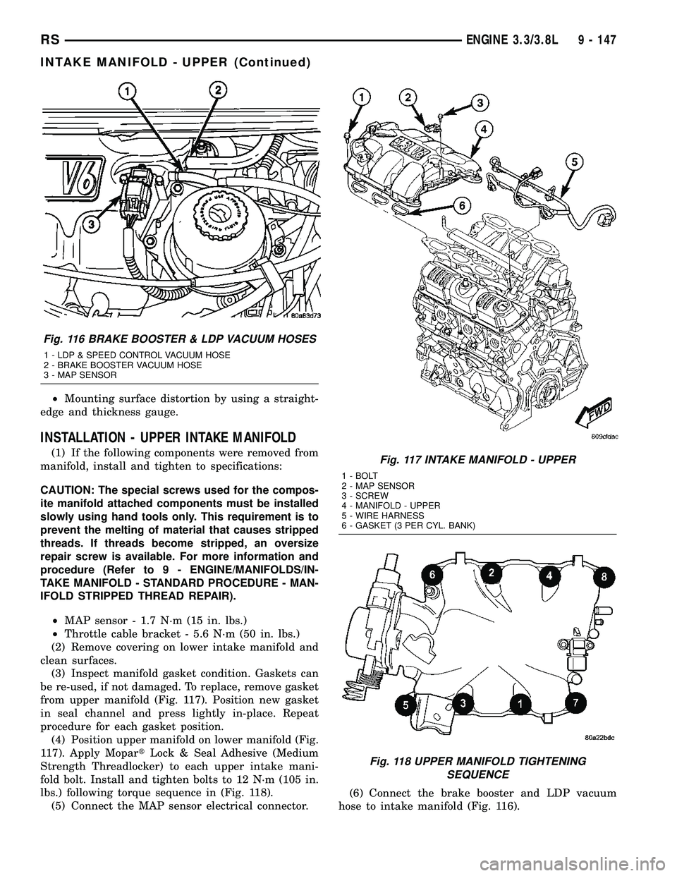
from upper manifold (Fig. 117). Position new gasket
in seal channel and press lightly in-place. Repeat
procedure for each gasket position.
(4) Position upper manifold on lower manifold (Fig.
117). Apply MopartLock & Seal Adhesive (Medium
Strength Threadlocker) to each upper intake mani-
fold bolt. Install and tighten bolts to 12 N´m (105 in.
lbs.) following torque sequence in (Fig. 118).
(5) Connect the MAP sensor electrical connector.(6) Connect the brake booster and LDP vacuum
hose to intake manifold (Fig. 116).
Fig. 116 BRAKE BOOSTER & LDP VACUUM HOSES
1 - LDP & SPEED CONTROL VACUUM HOSE
2 - BRAKE BOOSTER VACUUM HOSE
3 - MAP SENSOR
Fig. 117 INTAKE MANIFOLD - UPPER
1 - BOLT
2 - MAP SENSOR
3 - SCREW
4 - MANIFOLD - UPPER
5 - WIRE HARNESS
6 - GASKET (3 PER CYL. BANK)
Fig. 118 UPPER MANIFOLD TIGHTENING
SEQUENCE
RSENGINE 3.3/3.8L9 - 147
INTAKE MANIFOLD - UPPER (Continued)
Page 1446 of 2585

²Check for cylinder head mounting surface distor-
tion using a straightedge and thickness gauge. (Refer
to 9 - ENGINE/CYLINDER HEAD - INSPECTION)
INSTALLATION - LOWER INTAKE MANIFOLD
(1) Place a bead (approximately 1/4 in. diameter)
of MopartEngine RTV GEN II onto each of thefour
manifold to cylinder head gasket corners (Fig. 122).
(2) Carefully install the new intake manifold gas-
ket (Fig. 121). Tighten end seal retainer screws to 12
N´m (105 in. lbs.).
(3) Install lower intake manifold (Fig. 121). Install
the bolts and torque to 1 N´m (10 in. lbs.). Then
torque bolts to 22 N´m (200 in. lbs.) in sequence
shown in (Fig. 123). Then torque again to 22 N´m
(200 in. lbs.). After intake manifold is in place,
inspect to make sure seals are in place.
(4) Install the fuel injectors and rail assembly.
(Refer to 14 - FUEL SYSTEM/FUEL DELIVERY/
FUEL RAIL - INSTALLATION)
(5) Connect fuel injector electrical harness.
(6) Connect the engine coolant temperature sensor
(Fig. 120).
(7) Connect the heater supply (Fig. 120) and radi-
ator upper hoses to manifold.
(8) Connect the fuel line. (Refer to 14 - FUEL SYS-
TEM/FUEL DELIVERY/QUICK CONNECT FIT-
TING - STANDARD PROCEDURE)(9) Install the upper intake manifold. (Refer to 9 -
ENGINE/MANIFOLDS/INTAKE MANIFOLD -
INSTALLATION)
(10) Connect negative battery cable.
Fig. 120 ECT SENSOR & HEATER SUPPLY
1 - ENGINE COOLANT TEMPERATURE SENSOR
2 - CONNECTOR - ENGINE COOLANT SENSOR
3 - FITTING - HEATER SUPPLY
Fig. 121 INTAKE MANIFOLD - LOWER
1 - INTAKE MANIFOLD - LOWER
2 - BOLT - GASKET END SEAL RETAINER
3 - GASKET
4 - BOLT - LOWER INTAKE MANIFOLD
Fig. 122 Intake Manifold Gasket Sealing
1 - SEALER LOCATIONS
RSENGINE 3.3/3.8L9 - 149
INTAKE MANIFOLD - LOWER (Continued)
Page 1450 of 2585

VALVE TIMING
STANDARD PROCEDURE
STANDARD PROCEDURE - VALVE TIMING
VERIFICATION
(1) Remove front cylinder head cover and all 6
spark plugs.
(2) Rotate engine until the #2 piston is at TDC of
the compression stroke.
(3) Install a degree wheel on the crankshaft pulley.
(4) With proper adaptor, install a dial indicator
into #2 spark plug hole. Using the indicator find TDC
on the compression stroke.
(5) Position the degree wheel to zero.
(6) Remove dial indicator from spark plug hole.
(7) Place a 5.08 mm (0.200 in.) spacer between the
valve stem tip of #2 intake valve and rocker arm pad.
Allow tappet to bleed down to give a solid tappet
effect.
(8) Install a dial indicator so plunger contacts the
#2 intake valve spring retainer as nearly perpendic-
ular as possible. Zero the indicator.
(9) Rotate the engine clockwise until the intake
valve has lifted .254 mm (0.010 in.).
CAUTION: Do not turn crankshaft any further clock-
wise as intake valve might bottom and result in
serious damage.
(10) Degree wheel should read 6 degrees BTDC to
6 degrees ATDC.
STANDARD PROCEDURE - MEASURING
TIMING CHAIN WEAR
NOTE: This procedure must be performed with the
timing chain cover removed (Refer to 9 - ENGINE/
VALVE TIMING/TIMING CHAIN COVER - REMOVAL).
(1) Position a scale next to timing chain so that
any movement of chain may be measured (Fig. 132).
(2) Position a torque wrench and socket on the
camshaft sprocket attaching bolt. Apply force in the
direction of crankshaft rotation to take up slack to
the following torque:
²41 N´m (30 ft. lb.) with cylinder heads installed
²20 N´m (15 ft. lb.) with cylinder heads removed
NOTE: With torque applied to the camshaft
sprocket bolt, crankshaft should not be permitted to
move. It may be necessary to block crankshaft to
prevent rotation.
(3) Holding a measuring scale along edge of chain
links (Fig. 132).(4) Apply force in the reverse direction to the fol-
lowing torque:
²41 N´m (30 ft. lb.) with cylinder heads installed
²20 N´m (15 ft. lb.) with cylinder heads removed
(5) Measure amount of sprocket/chain movement.
(6) Install a new timing chain and sprockets if
movement exceeds 3.175 mm (1/8 in.).
TIMING CHAIN COVER
REMOVAL
(1) Disconnect negative cable from battery.
(2) Drain cooling system. (Refer to 7 - COOLING -
STANDARD PROCEDURE)
(3) Raise vehicle on hoist.
(4) Drain engine oil.
(5) Remove right wheel and inner splash shield.
(6) Remove oil pan. (Refer to 9 - ENGINE/LUBRI-
CATION/OIL PAN - REMOVAL)
(7) Remove oil pick-up tube (Fig. 133).
(8) Remove accessory drive belt. (Refer to 7 -
COOLING/ACCESSORY DRIVE/DRIVE BELTS -
REMOVAL)
(9) Remove A/C compressor and set aside.
(10) Remove crankshaft vibration damper. (Refer
to 9 - ENGINE/ENGINE BLOCK/VIBRATION
DAMPER - REMOVAL)
(11) Remove radiator lower hose.
(12) Remove heater hose from timing chain cover
housing (Fig. 134) or water pump inlet tube (if
engine oil cooler equipped) (Fig. 135).
(13) Remove the right side engine mount. (Refer to
9 - ENGINE/ENGINE MOUNTING/RIGHT MOUNT
- REMOVAL)
(14) Remove idler pulley from engine bracket (Fig.
136).
(15) Remove the engine mount bracket (Fig. 136).
Fig. 132 Measuring Timing Chain Wear
1 - TORQUE WRENCH
RSENGINE 3.3/3.8L9 - 153
Page 1463 of 2585

(1) Install the main bearing upper shells with the
lubrication groove and oil hole in the engine block
(Fig. 6).
(2) Make certain oil holes in block line up with oil
hole in bearings and bearing tabs seat in the block
tab slots.
NOTE: If the crankshaft is sent out for machine
work, it must be balenced as an assembly with the
target ring installed.
(3) Clean crankshaft and target ring with
MOPARtbrake parts cleaner and dry with com-
pressed air to ensure that the crankshaft mating sur-
face and target ring mounting holes are free from oil
and lock patch debris.
NOTE: Always use NEW mounting screws whether
installing original or new target ring.
(4) InstallNEWmounting screws finger tight
starting with the #1 location. (Fig. 7) Make sure
engagment occurs with the shoulder of the screw and
mounting hole before starting all other screws.
(5) Torque all mounting screws with T30 torx bit
to 13 Nm (110 in-lbs) following the torque sequence.
CAUTION: Use extreme care when handling crank-
shaft. Tone wheel damage can occur if crankshaft is
mis-handled.
CAUTION: Do not get oil on the bed plate mating
surface. It will affect the ability of the sealer to seal
the bed plate to cylinder block.(6) Oil the bearings and journals. Install crank-
shaft in the engine block.
CAUTION: Use only MoparTBed Plate Sealant on
the bed plate or damage may occur to the engine.
(7) Install lower main bearings into main bearing
cap/bed plate. Make certain the bearing tabs are
seated into the bed plate slots and apply oil.
(8) Apply 1.5 to 2.0 mm (0.059 to 0.078 in.) bead of
MopartBed Plate Sealant to bed plate as shown in
(Fig. 8).
Fig. 6 Installing Main Bearing Upper Shell
1 - LUBRICATION GROOVES
2 - OIL HOLESFig. 7 Target Ring Torque Sequence
Fig. 8 Bed Plate Sealing
9s - 8 ENGINE 2.4L SUPPLEMENTRS
CRANKSHAFT (Continued)
Page 1464 of 2585

(9) Install the main bearing/bed plate into engine
block.
(10) Before installing the bolts the threads should
be oiled with clean engine oil, wipe off any excess oil.
(11) Install main bearing bed plate to engine
block bolts 11, 17, and 20 finger tight. Tighten these
bolts down together until the bed plate contacts the
cylinder block.
(12) To ensure correct thrust bearing alignment,
perform the following steps:
²Step 1: Rotate crankshaft until number 4 piston
is at TDC.
²Step 2: Move crankshaft rearward to limits of
travel.
²Step 3: Then, move crankshaft forward to limits
of travel.
²Step 4: Wedge an appropriate tool between the
rear of the cylinder block(NOT BED PLATE)and
the rear crankshaft counterweight. This will hold the
crankshaft in it's furthest forward position.
²Step 5: Install and tighten bolts (1±10) in
sequence shown in (Fig. 9) to 41 N´m (30 ft. lbs.).
²Step 6: Remove wedge tool used to hold crank-
shaft.
(13) Tighten bolts (1±10) again to 41 N´m (30 ft.
lbs.) in sequence shown in (Fig. 9).
CAUTION: Do Not use a torque wrench for the fol-
lowing step.
(14) Turn bolts (1±10) an additional 1/4 turn in
sequence shown in (Fig. 9).(15) Install main bearing bed plate to engine
block bolts (11±20), and torque each bolt to 28 N´m
(250 in. lbs.) in sequence shown in. (Fig. 9)
(16) Tighten bolts (11±20) again to 28 N´m (250 in.
lbs.) in sequence shown in (Fig. 9).
(17) After the main bearing bed plate is installed,
check the crankshaft turning torque. The turning
torque should not exceed 5.6 N´m (50 in. lbs.).
(18) Check crankshaft end play (Refer to 9 -
ENGINE/ENGINE BLOCK/CRANKSHAFT - STAN-
DARD PROCEDURE).
(19) Install connecting rod bearings and caps.Do
Not Reuse Connecting Rod Bolts.Torque connect-
ing rod bolts to 27 N´m (20 ft. lbs.) plus 1/4 turn.
(20) Install balance shafts and housing assembly
(Refer to 9 - ENGINE/VALVE TIMING/BALANCE
SHAFT - INSTALLATION).
(21) Install the oil pump (Refer to 9 - ENGINE/
LUBRICATION/OIL PUMP - INSTALLATION).
(22) Install oil pump pick-up tube. Torque fastener
to 28 N´m (20 ft.. lbs.).
(23) Install the oil pan (Refer to 9 - ENGINE/LU-
BRICATION/OIL PAN - INSTALLATION).
(24) Install crankshaft position sensor.
(25) Install cylinder head if it was removed (Refer
to 9 - ENGINE/CYLINDER HEAD - INSTALLA-
TION).
(26) Install the timing belt rear cover (Refer to 9 -
ENGINE/VALVE TIMING/TIMING BELT COVER(S)
- INSTALLATION).
(27) Install crankshaft sprocket (Refer to 9 -
ENGINE/VALVE TIMING/TIMING BELT AND
SPROCKETS - INSTALLATION).
(28) Install the timing belt (Refer to 9 - ENGINE/
VALVE TIMING/TIMING BELT AND SPROCKETS -
INSTALLATION).
(29) Install the timing belt front covers (Refer to 9
- ENGINE/VALVE TIMING/TIMING BELT COV-
ER(S) - INSTALLATION).
(30) Install engine mount support bracket.
(31) InstallNEWoil filter.
(32) Install crankshaft rear oil seal (Refer to 9 -
ENGINE/ENGINE BLOCK/CRANKSHAFT OIL
SEAL - REAR - INSTALLATION).
(33) Install flex plate. Apply MopartLock & Seal
Adhesive to bolt threads and tighten to 95 N´m (70
ft. lbs.).
(34) Attach transaxle to engine. Tighten attaching
bolts to 101 N´m (75 ft. lbs.).
(35) Install the engine assembly (Refer to 9 -
ENGINE - INSTALLATION).
Fig. 9 Main Bearing Caps/Bed Plate Bolt Torque
Sequence
RSENGINE 2.4L SUPPLEMENT9s-9
CRANKSHAFT (Continued)
Page 1473 of 2585

²Standard dimension = less than 0.05 mm (0.002
inch.)
²Service Limit = 0.2 mm (0.008 inch.)
²Grinding Limit = Maximum of 0.2 mm (0.008
inch.) is permitted.
CAUTION: 0.20 mm (0.008 in.) MAX is a combined
total dimension of the stock removal limit from cyl-
inder head and block top surface (Deck) together.
INSTALLATION - CYLINDER HEAD
(1) Clean all sealing surfaces of engine block and
cylinder heads. (Refer to 9 - ENGINE - STANDARD
PROCEDURE)
(2) Position new gasket(s) on engine block (Fig. 4).
The left bank gasket is identified with the ªLº
stamped in the exposed area of the gasket located at
front of engine (shown in (Fig. 4)). The right bank
gasket is identified with a ªRº stamped in the
exposed area of the gasket also, but is located at the
rear of the engine.(3)The cylinder head bolts are torqued using
the torque yield method, they should be exam-
ined BEFORE reuse. If the threads are necked
down, the bolts must be replaced(Fig. 5).
(4) Necking can be checked by holding a scale or
straight edge against the threads. If all the threads
do not contact the scale the bolt should be replaced.
(5) Tighten the cylinder head bolts 1±8 in the
sequence shown in (Fig. 6). Using the 4 step torque
turn method, tighten according to the following val-
ues:
²Step 1: Bolts1±8to61N´m(45ft.lbs.)
²Step 2: Bolts1±8to88N´m(65ft.lbs.)
²Step 3: Bolts1±8(again) to 88 N´m (65 ft. lbs.)
²Step 4: Bolts1±8turn an additional 1/4 Turn.
(Do not use a torque wrench for this step.)
NOTE: Bolt torque after 1/4 turn should be over 122
N´m (90 ft. lbs.). If not, replace the bolt.
(6) Inspect push rods and replace worn or bent
rods.
(7) Install the push rods.
(8) Install the rocker arm and shaft assemblies.
(Refer to 9 - ENGINE/CYLINDER HEAD/ROCKER
ARMS - INSTALLATION)
(9) Install the cylinder head covers. (Refer to 9 -
ENGINE/CYLINDER HEAD/CYLINDER HEAD
COVER(S) - INSTALLATION)
Fig. 3 Checking Cylinder Head FlatnessÐTypical
Fig. 4 Head Gasket Installation
1 - CYLINDER HEAD GASKET
2 - LOCATION IDENTIFICATION (L = LEFT BANK, R = RIGHT
BANK)
Fig. 5 Checking Bolts for Stretching (Necking)
1 - STRETCHED BOLT
2 - THREADS ARE NOT STRAIGHT ON LINE
3 - THREADS ARE STRAIGHT ON LINE
4 - UNSTRETCHED BOLT
Fig. 6 CYLINDER HEAD TIGHTENING SEQUENCE
9s - 18 ENGINE 3.3/3.8L SUPPLEMENTRS
CYLINDER HEAD (Continued)
Page 1474 of 2585

(10) Install the exhaust manifolds. (Refer to 9 -
ENGINE/MANIFOLDS/EXHAUST MANIFOLD -
INSTALLATION)
(11) Install new O-ring on dipstick tube. Install
dipstick tube assembly (Fig. 2).
(12) Install the spark plugs.
(13) Install upper and lower intake manifolds.
(Refer to 9 - ENGINE/MANIFOLDS/INTAKE MANI-
FOLD - INSTALLATION)
(14) Fill the cooling system. (Refer to 7 - COOL-
ING - STANDARD PROCEDURE)
(15) Connect negative cable to battery.
CYLINDER HEAD COVER(S)
DESCRIPTION
The cylinder head covers are made of stamped
steel. The covers are sealed with steel reinforced sil-
icon rubber gaskets. The cylinder head cover uses
rubber isolators at each fastener location (Fig. 7).
NOTE: Due to the tight packaging near the cylinder
head covers, which makes spill clean-up difficult, a
spill during an engine oil change may be misinter-
preted as an oil leak. When investigating an oil leak
in the location of the cylinder head covers and
intake manifold, follow the procedure found in Oil
Leak Diagnosis (Refer to 9 - ENGINE - DIAGNOSIS
AND TESTING) for determining the source of a leak.
CYLINDER HEAD COVER-
RIGHT
REMOVAL
(1) Disconnect negative cable from battery.
(2) Remove the wiper module. (Refer to 8 - ELEC-
TRICAL/WIPERS/WASHERS/WIPER MODULE -
REMOVAL)
(3) Disconnect spark plug wires from plugs.
(4) Disconnect PCV hose from cylinder head cover
(Fig. 8).
(5) Remove cylinder head cover bolts.
(6) Remove cylinder head cover and gasket (Fig.
7).
INSTALLATION
(1) Clean cylinder head and cover mating surfaces.
Inspect cylinder head cover surface for flatness.
Replace gasket as necessary.
(2) Inspect seal on the cover bolt for wear or dam-
age (Fig. 9). Replace bolt assembly as necessary.
NOTE: The cylinder head cover bolts contain a
torque limiter sleeve and a seal (Fig. 9). The seal
and torque sleeve is replaced with the bolt.
Fig. 7 Cylinder Head Cover
1 - CYLINDER HEAD COVER
2 - BOLT
Fig. 8 PCV Hose
1 - HOSE - PCV
2 - P C V VA LV E
RSENGINE 3.3/3.8L SUPPLEMENT9s-19
CYLINDER HEAD (Continued)
Page 1480 of 2585

(7) Install a spark plug adapter in the spark plug
hole. Connect air hose that can supply 620.5±689 kPa
(90±100 psi) of air pressure to adapter. This is to
hold valves in place while servicing components.
(8) Locate the forcing screw and spring retainer
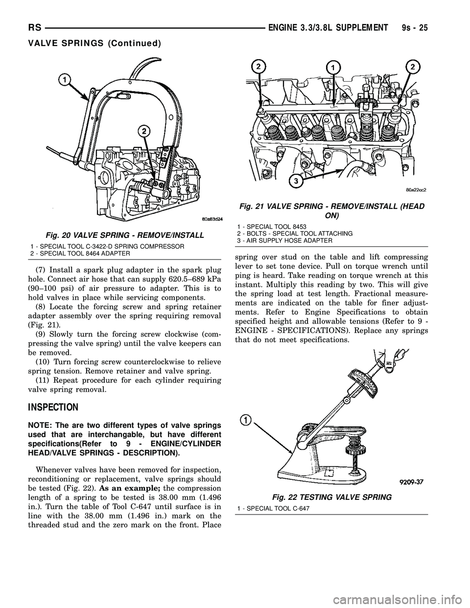
adapter assembly over the spring requiring removal
(Fig. 21).
(9) Slowly turn the forcing screw clockwise (com-
pressing the valve spring) until the valve keepers can
be removed.
(10) Turn forcing screw counterclockwise to relieve
spring tension. Remove retainer and valve spring.
(11) Repeat procedure for each cylinder requiring
valve spring removal.
INSPECTION
NOTE: The are two different types of valve springs
used that are interchangable, but have different
specifications(Refer to 9 - ENGINE/CYLINDER
HEAD/VALVE SPRINGS - DESCRIPTION).
Whenever valves have been removed for inspection,
reconditioning or replacement, valve springs should
be tested (Fig. 22).As an example;the compression
length of a spring to be tested is 38.00 mm (1.496
in.). Turn the table of Tool C-647 until surface is in
line with the 38.00 mm (1.496 in.) mark on the
threaded stud and the zero mark on the front. Placespring over stud on the table and lift compressing
lever to set tone device. Pull on torque wrench until
ping is heard. Take reading on torque wrench at this
instant. Multiply this reading by two. This will give
the spring load at test length. Fractional measure-
ments are indicated on the table for finer adjust-
ments. Refer to Engine Specifications to obtain
specified height and allowable tensions (Refer to 9 -
ENGINE - SPECIFICATIONS). Replace any springs
that do not meet specifications.
Fig. 20 VALVE SPRING - REMOVE/INSTALL
1 - SPECIAL TOOL C-3422-D SPRING COMPRESSOR
2 - SPECIAL TOOL 8464 ADAPTER
Fig. 21 VALVE SPRING - REMOVE/INSTALL (HEAD
ON)
1 - SPECIAL TOOL 8453
2 - BOLTS - SPECIAL TOOL ATTACHING
3 - AIR SUPPLY HOSE ADAPTER
Fig. 22 TESTING VALVE SPRING
1 - SPECIAL TOOL C-647
RSENGINE 3.3/3.8L SUPPLEMENT9s-25
VALVE SPRINGS (Continued)
Page 1486 of 2585

EXHAUST SYSTEM
TABLE OF CONTENTS
page page
EXHAUST SYSTEM
DESCRIPTION..........................1
DIAGNOSIS AND TESTING
DIAGNOSIS AND TESTING - EXCESSIVE
EXHAUST SYSTEM NOISE...............2
DIAGNOSIS AND TESTING - EXHAUST
SYSTEM RESTRICTION CHECK...........2
INSPECTION...........................3
ADJUSTMENTS.........................3
SPECIFICATIONS
TORQUE.............................3
SPECIAL TOOLS
EXHAUST SYSTEM.....................4
CATALYTIC CONVERTER
DESCRIPTION..........................4
OPERATION............................4
REMOVAL.............................5INSPECTION...........................5
INSTALLATION..........................6
CROSS-OVER PIPE - 3.3/3.8L
REMOVAL.............................6
INSTALLATION..........................6
HEAT SHIELDS
DESCRIPTION..........................6
OPERATION............................7
REMOVAL.............................7
INSTALLATION..........................7
MUFFLER
REMOVAL.............................7
INSTALLATION..........................7
RESONATOR
REMOVAL.............................9
INSTALLATION..........................9
EXHAUST SYSTEM
DESCRIPTION
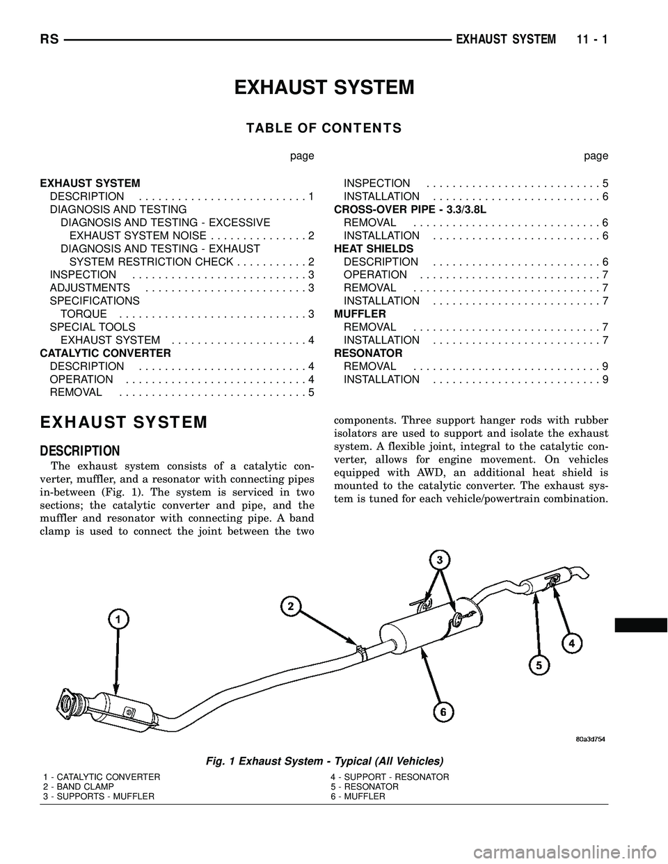
The exhaust system consists of a catalytic con-
verter, muffler, and a resonator with connecting pipes
in-between (Fig. 1). The system is serviced in two
sections; the catalytic converter and pipe, and the
muffler and resonator with connecting pipe. A band
clamp is used to connect the joint between the twocomponents. Three support hanger rods with rubber
isolators are used to support and isolate the exhaust
system. A flexible joint, integral to the catalytic con-
verter, allows for engine movement. On vehicles
equipped with AWD, an additional heat shield is
mounted to the catalytic converter. The exhaust sys-
tem is tuned for each vehicle/powertrain combination.
Fig. 1 Exhaust System - Typical (All Vehicles)
1 - CATALYTIC CONVERTER 4 - SUPPORT - RESONATOR
2 - BAND CLAMP 5 - RESONATOR
3 - SUPPORTS - MUFFLER 6 - MUFFLER
RSEXHAUST SYSTEM11-1
Page 1488 of 2585

(4) Following the PEP module instruction manual,
connect all required cables to the DRB IIItand PEP
module. Select the available menu options on the
DRBIIItdisplay screen for using the digital pressure
gauge function.
(5) Apply the park brake and start the engine.
(6) With transmission in Park or Neutral, raise
engine speed to 2000 RPM. Monitor the pressure
readings on the DRBIIIt. Back pressure should not
exceed specified limit. Refer to specification in table
below EXHAUST BACK PRESSURE LIMITS .
(7) If pressure exceeds maximum limits, inspect
exhaust system for restricted component. For further
catalytic converter inspection procedures, (Refer to 11
- EXHAUST SYSTEM/CATALYTIC CONVERTER -
INSPECTION). Replace component(s) as necessary.
EXHAUST BACK PRESSURE LIMITS
Exhaust Back Pressure Limit (Max)
Vehicle in Park/Neutral
(no load) @2000 RPM3.45 Kpa (0.5 psi)
INSPECTION
Inspect the exhaust pipes, catalytic converters,
muffler, and resonators for cracked joints, broken
welds and corrosion damage that would result in a
leaking exhaust system. Inspect the clamps, support
brackets, and insulators for cracks and corrosion
damage.
NOTE: Slip joint band clamps are spot welded to
exhaust system. If a band clamp must be replaced,
the spot weld must be ground off.
ADJUSTMENTS
A misaligned exhaust system is usually indicated
by a vibration, rattling noise, or binding of exhaust
system components. These noises are sometimes hard
to distinguish from other chassis noises. Inspect
exhaust system for broken, damaged or loose compo-
nents such as; clamps, heat shields, isolators, and
hanger brackets. Replace or tighten as necessary. It
is important that exhaust system clearances and
alignment be maintained.
Perform the following procedures to align the
exhaust system:
(1) Loosen band clamp at catalytic converter pipe
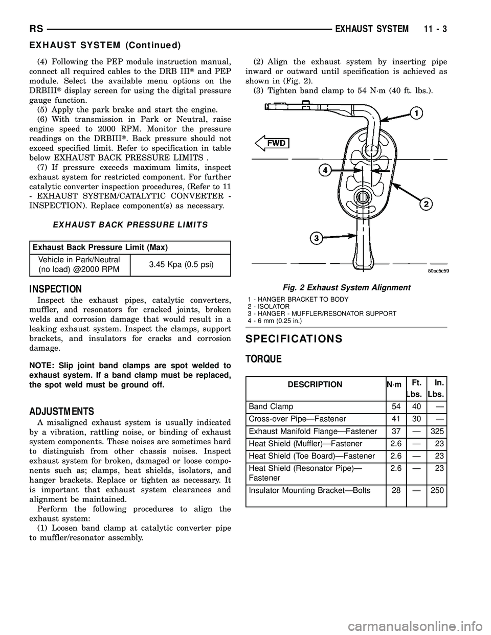
to muffler/resonator assembly.(2) Align the exhaust system by inserting pipe
inward or outward until specification is achieved as
shown in (Fig. 2).
(3) Tighten band clamp to 54 N´m (40 ft. lbs.).
SPECIFICATIONS
TORQUE
DESCRIPTION N´mFt.
Lbs.In.
Lbs.
Band Clamp 54 40 Ð
Cross-over PipeÐFastener 41 30 Ð
Exhaust Manifold FlangeÐFastener 37 Ð 325
Heat Shield (Muffler)ÐFastener 2.6 Ð 23
Heat Shield (Toe Board)ÐFastener 2.6 Ð 23
Heat Shield (Resonator Pipe)Ð
Fastener2.6 Ð 23
Insulator Mounting BracketÐBolts 28 Ð 250
Fig. 2 Exhaust System Alignment
1 - HANGER BRACKET TO BODY
2 - ISOLATOR
3 - HANGER - MUFFLER/RESONATOR SUPPORT
4-6mm(0.25 in.)
RSEXHAUST SYSTEM11-3
EXHAUST SYSTEM (Continued)