8e electrical CHRYSLER VOYAGER 2004 Service Manual
[x] Cancel search | Manufacturer: CHRYSLER, Model Year: 2004, Model line: VOYAGER, Model: CHRYSLER VOYAGER 2004Pages: 2585, PDF Size: 62.54 MB
Page 2131 of 2585
TRIM PANEL
REMOVAL
(1) Remove the plug and remove screw attaching
door pull cup to inner door panel.
(2) Remove switch bezel and disconnect power win-
dow/memory switch.
(3) Remove screws attaching trim panel to door
from below map pocket.
(4) If equipped, remove window crank. (Refer to 23
- BODY/DOOR - FRONT/WINDOW CRANK -
REMOVAL)
(5) Remove screw holding door trim to door panel
from behind inside latch release handle.
(6) Disengage clips attaching door trim to door
frame around perimeter of panel.
(7) Lift trim panel upward to disengage flange
from inner belt molding at top of door.
(8) Tilt top of trim panel away from door to gain
access to latch linkage.
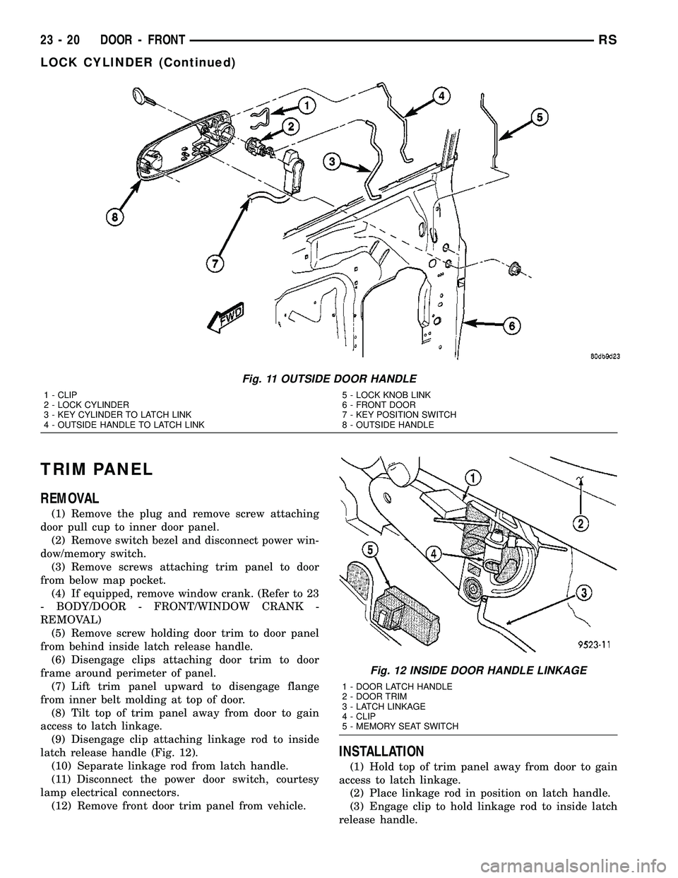
(9) Disengage clip attaching linkage rod to inside
latch release handle (Fig. 12).
(10) Separate linkage rod from latch handle.
(11) Disconnect the power door switch, courtesy
lamp electrical connectors.
(12) Remove front door trim panel from vehicle.
INSTALLATION
(1) Hold top of trim panel away from door to gain
access to latch linkage.
(2) Place linkage rod in position on latch handle.
(3) Engage clip to hold linkage rod to inside latch
release handle.
Fig. 11 OUTSIDE DOOR HANDLE
1 - CLIP
2 - LOCK CYLINDER
3 - KEY CYLINDER TO LATCH LINK
4 - OUTSIDE HANDLE TO LATCH LINK5 - LOCK KNOB LINK
6 - FRONT DOOR
7 - KEY POSITION SWITCH
8 - OUTSIDE HANDLE
Fig. 12 INSIDE DOOR HANDLE LINKAGE
1 - DOOR LATCH HANDLE
2 - DOOR TRIM
3 - LATCH LINKAGE
4 - CLIP
5 - MEMORY SEAT SWITCH
23 - 20 DOOR - FRONTRS
LOCK CYLINDER (Continued)
Page 2132 of 2585
(4) Place front door trim panel in position on door.
(5) Install trim panel into inner belt molding at
top of door.
(6) Install clips to attach door trim to door frame
around perimeter of panel.
(7) If equipped, install screw to attach door trim to
door panel behind inside latch release handle.
(8) If equipped, connect power switch into wire
connector.
(9) Place power accessary switch in position on
door trim.
(10) Connect wire connector into memory seat/mir-
ror switch and install switch into trim panel.
(11) Install screws to attach accessary switch
panel to door trim.
(12) Install screw cover into switch panel.
(13) If equipped, install window crank.
(14) If equipped, install screws to attach trim
panel to door inside map pocket.
(15) If equipped, install screw to attach door pull
cup to inner door panel.
(16) If equipped, install screws to attach door
assist handle to inner door panel.
(17) Connect wire connector into courtesy lamp.
(18) Install lamp in door trim.
(19) Install switch bezel.
WATERSHIELD
REMOVAL
(1) Remove door trim panel. (Refer to 23 - BODY/
DOOR - FRONT/TRIM PANEL - REMOVAL)
(2) Remove the front door speaker. (Refer to 8 -
ELECTRICAL/AUDIO/SPEAKER - REMOVAL)
(3) Peel watershield away from adhesive around
perimeter of inner door panel.
INSTALLATION
(1) Insure that enough adhesive remains to
securely retain the water dam. Replace as necessary.
(2) Place the shield into position and press
securely to adhesive making sure to properly route
wiring and linkages.
(3) Install the front door speaker. (Refer to 8 -
ELECTRICAL/AUDIO/SPEAKER - INSTALLATION)
(4) Install door trim panel. (Refer to 23 - BODY/
DOOR - FRONT/TRIM PANEL - INSTALLATION)
WINDOW CRANK
REMOVAL
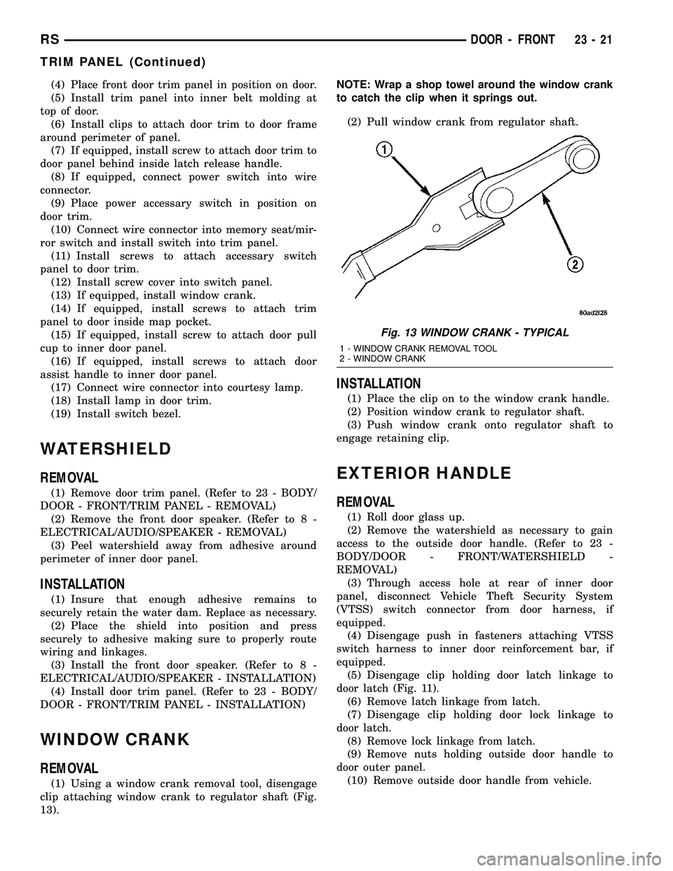
(1) Using a window crank removal tool, disengage
clip attaching window crank to regulator shaft (Fig.
13).NOTE: Wrap a shop towel around the window crank
to catch the clip when it springs out.
(2) Pull window crank from regulator shaft.
INSTALLATION
(1) Place the clip on to the window crank handle.
(2) Position window crank to regulator shaft.
(3) Push window crank onto regulator shaft to
engage retaining clip.
EXTERIOR HANDLE
REMOVAL
(1) Roll door glass up.
(2) Remove the watershield as necessary to gain
access to the outside door handle. (Refer to 23 -
BODY/DOOR - FRONT/WATERSHIELD -
REMOVAL)
(3) Through access hole at rear of inner door
panel, disconnect Vehicle Theft Security System
(VTSS) switch connector from door harness, if
equipped.
(4) Disengage push in fasteners attaching VTSS
switch harness to inner door reinforcement bar, if
equipped.
(5) Disengage clip holding door latch linkage to
door latch (Fig. 11).
(6) Remove latch linkage from latch.
(7) Disengage clip holding door lock linkage to
door latch.
(8) Remove lock linkage from latch.
(9) Remove nuts holding outside door handle to
door outer panel.
(10) Remove outside door handle from vehicle.
Fig. 13 WINDOW CRANK - TYPICAL
1 - WINDOW CRANK REMOVAL TOOL
2 - WINDOW CRANK
RSDOOR - FRONT23-21
TRIM PANEL (Continued)
Page 2149 of 2585
CAUTION: Make note of cable routing and foam
insulator placement. This will prove helpful when
reinstalling replacement cable. Be certain replace-
ment cable is routed and retained correctly.
(7) Trace the inside handle cable along its routing
path and disconnect from its retaining clips.
(8) Disconnect the inside handle cable from the
latch assembly. Gently pry cable sleeve retainer out
of the latch mounting bracket and then unhook
swedged cable end from the latch link.
(9) Remove the inside handle cable from the side
door.
INSTALLATION
NOTE: For power sliding door procedures refer to
POWER SLIDING DOOR SYSTEM in the ELECTRI-
CAL section.
(1) Match the replacement cable up against the old
cable to verify the correct part.
(2) Position the inside handle cable on the side
door.
(3) Connect the inside handle cable on the handle
assembly. Hook the swedged cable end on the handle
link and gently push the cable sleeve retainer in the
handle bracket.
(4) Install the inside handle assembly on the side
door. (Refer to 23 - BODY/DOORS - SLIDING/IN-
SIDE LATCH HANDLE - INSTALLATION)
NOTE: The inside handle cable is marked with blue
tape and must be attached to the latch at the center
(just above the lower cable). This position is
marked with a ªBº on the latch.
(5) Connect the inside handle cable on the latch
assembly. Hook the swedged cable end on the latch
link and gently push the cable sleeve retainer in the
latch bracket.
(6) Trace the inside handle cable along its routing
path and install on its retaining clips and position
foam insulators. Use previously made schematic as a
guide or remove the opposite side door trim panel
and use that door as a guide.
CAUTION: Be certain replacement cable is routed
and retained correctly and foam insulators are
properly positioned.
(7) Install the latch assembly. Refer to the Power
Side Doors section for the procedure.
(8) Place the watershield into position and press
securely to adhesive making sure to properly route
wiring and linkages.(9) Install the appropriate side door trim panel on
the vehicle. (Refer to 23 - BODY/DOORS - SLIDING/
TRIM PANEL - INSTALLATION)
(10) Connect the negative battery cable.
HOLD OPEN LATCH CABLE
REMOVAL
NOTE: For power sliding door procedures refer to
POWER SLIDING DOOR SYSTEM in the ELECTRI-
CAL section.
(1) Disconnect and isolate the negative battery
cable.
(2) Remove the appropriate side door trim panel
from the vehicle. (Refer to 23 - BODY/DOORS -
SLIDING/TRIM PANEL - REMOVAL)
(3) Peel watershield away from adhesive around
perimeter of inner door panel.
(4) Open the side door and remove the latch
assembly. (Refer to 8 - ELECTRICAL/POWER
DOORS/LATCH - REMOVAL)
CAUTION: Make note of cable routing and foam
insulator placement. This will prove helpful when
reinstalling replacement cable. Be certain replace-
ment cable is routed and retained correctly.
(5) Trace the hold open latch cable along its rout-
ing path and disconnect from its retaining clips.
(6) Disconnect the hold open latch cable from the
latch assembly. Gently pry cable sleeve retainer out
of the latch mounting bracket and then unhook
swedged cable end from the latch link.
(7) Remove the hold open latch from the side door.
(Refer to 23 - BODY/DOORS - SLIDING/HOLD
OPEN LATCH - REMOVAL)
(8) Disconnect the hold open latch cable from the
hold open latch. Gently pry cable sleeve retainer out
of the handle bracket and then unhook swedged
cable end from the latch link.
(9) Remove the hold open latch cable from the side
door.
INSTALLATION
NOTE: For power sliding door procedures refer to
POWER SLIDING DOOR SYSTEM in the ELECTRI-
CAL section.
(1) Match the replacement cable up against the old
cable to verify the correct part.
(2) Position the hold open latch cable on the side
door.
23 - 38 DOORS - SLIDINGRS
INSIDE HANDLE CABLE (Continued)
Page 2151 of 2585

DECKLID/HATCH/LIFTGATE/TAILGATE
TABLE OF CONTENTS
page page
EXTERIOR HANDLE
REMOVAL.............................40
INSTALLATION.........................40
HINGE
REMOVAL.............................40
INSTALLATION.........................40
LATCH
REMOVAL.............................41
INSTALLATION.........................41
LATCH STRIKER
REMOVAL.............................41
INSTALLATION.........................41
LIFTGATE
REMOVAL.............................42
INSTALLATION.........................42
LIFTGATE SPOILER
REMOVAL.............................42INSTALLATION.........................42
LOCK CYLINDER
REMOVAL.............................42
INSTALLATION.........................42
SUPPORT CYLINDER
REMOVAL.............................43
INSTALLATION.........................43
TRIM PANEL
REMOVAL.............................43
INSTALLATION.........................44
SLAM BUMPER
REMOVAL
REMOVAL...........................44
REMOVAL - LIFTGATE SIDE.............44
INSTALLATION
INSTALLATION.......................44
INSTALLATION - LIFTGATE SIDE.........44
EXTERIOR HANDLE
REMOVAL
(1) Remove liftgate trim panel. (Refer to 23 -
BODY/DECKLID/HATCH/LIFTGATE/TAILGATE/
TRIM PANEL - REMOVAL)
(2) Disconnect the exterior handle electrical con-
nectors.
(3) Remove the two outer screws and the two inner
screws.
(4) Remove the exterior handle/license plate light
assembly.
INSTALLATION
(1) Route the exterior handle electrical connector
through the door and position handle.
(2) Install the two out screws and tighten to 20
N´m (15 ft. lbs.).
(3) Install the two inner bolts and tighten to 40
N´m (30 ft. lbs.).
(4) Connect the electrical connector.
(5) Install the trim panel. (Refer to 23 - BODY/
DECKLID/HATCH/LIFTGATE/TAILGATE/TRIM
PANEL - INSTALLATION)
HINGE
REMOVAL
(1) Release liftgate latch and open liftgate.
(2) Support liftgate on a suitable lifting device in
the full open position.
(3) Apply several layers of duct tape on the outside
of to roof across the gap to the lift gate to hold the
liftgate in position.
(4) Remove bolts attaching liftgate hinge to roof
header.
(5) Disconnect VTSS switch from the body har-
ness.
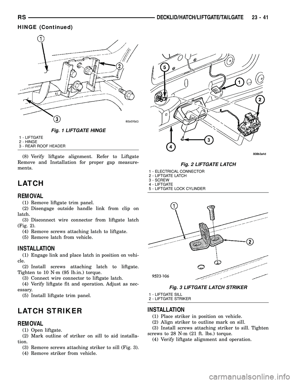
(6) Remove bolts attaching hinge to liftgate (Fig.
1).
(7) Remove hinge from vehicle.
INSTALLATION
(1) If necessary, paint replacement hinge before
installation.
(2) Place hinge in position on vehicle.
(3) Align hinge to marks on liftgate.
(4) Install bolts attaching hinge to liftgate (Fig. 1).
Tighten bolts to 33 N´m (24 ft. lbs.) torque.
(5) Align hinge to marks on roof header.
(6) Install bolts attaching liftgate hinge to roof
header. Tighten outer two bolts to 33 N´m (24 ft. lbs.)
torque. The sheet medal screw at center 12 N´m (105
in. lbs.)
(7) Remove duct tape from roof and liftgate.
23 - 40 DECKLID/HATCH/LIFTGATE/TAILGATERS
Page 2152 of 2585
(8) Verify liftgate alignment. Refer to Liftgate
Remove and Installation for proper gap measure-
ments.
LATCH
REMOVAL
(1) Remove liftgate trim panel.
(2) Disengage outside handle link from clip on
latch.
(3) Disconnect wire connector from liftgate latch
(Fig. 2).
(4) Remove screws attaching latch to liftgate.
(5) Remove latch from vehicle.
INSTALLATION
(1) Engage link and place latch in position on vehi-
cle.
(2) Install screws attaching latch to liftgate.
Tighten to 10 N´m (95 lb.in.) torque.
(3) Connect wire connector to liftgate latch.
(4) Verify liftgate fit and operation. Adjust as nec-
essary.
(5) Install liftgate trim panel.
LATCH STRIKER
REMOVAL
(1) Open liftgate.
(2) Mark outline of striker on sill to aid installa-
tion.
(3) Remove screws attaching striker to sill (Fig. 3).
(4) Remove striker from vehicle.
INSTALLATION
(1) Place striker in position on vehicle.
(2) Align striker to outline mark on sill.
(3) Install screws attaching striker to sill. Tighten
screws to 28 N´m (21 ft. lbs.) torque.
(4) Verify liftgate alignment and operation.
Fig. 1 LIFTGATE HINGE
1 - LIFTGATE
2 - HINGE
3 - REAR ROOF HEADER
Fig. 2 LIFTGATE LATCH
1 - ELECTRICAL CONNECTOR
2 - LIFTGATE LATCH
3 - SCREW
4 - LIFTGATE
5 - LIFTGATE LOCK CYLINDER
Fig. 3 LIFTGATE LATCH STRIKER
1 - LIFTGATE SILL
2 - LIFTGATE STRIKER
RSDECKLID/HATCH/LIFTGATE/TAILGATE23-41
HINGE (Continued)
Page 2153 of 2585

LIFTGATE
REMOVAL
(1) Release liftgate latch and open liftgate.
(2) Remove screws attaching liftgate wire connec-
tor to rear header.
(3) Disconnect liftgate wire harness from body
wire harness.
(4) Remove liftgate upper frame molding.
(5) Disconnect rear window washer hose from
spray nozzle.
(6) Support liftgate on a suitable lifting device.
(7) Remove screws attaching support cylinders to
liftgate.
(8) Remove bolts attaching liftgate hinge to roof
header (Fig. 4).
(9) With assistance, remove liftgate from vehicle.
INSTALLATION
(1) With assistance, place liftgate in position on
vehicle.
(2) Install bolts attaching liftgate hinge to roof
header. Tighten bolts to 33 N´m (24 ft. lbs.) torque.
(3) Install screws attaching support cylinders to
liftgate. Tighten bolts to 28 N´m (21 ft. lbs.) torque.
(4) Remove lifting device from under liftgate.
(5) Connect liftgate wire harness into body wire
harness.
(6) Install screws attaching wire connector to rear
header.
(7) Connect rear window washer hose onto spray
nozzle.
(8) Install liftgate upper frame molding.
(9) Verify liftgate alignment. The liftgate should
have a gap to adjacent panels and fit flush across the
gaps. The gap is;²7 mm (0.280 in.) to the fascia,
²6 mm (0.240 in.) to the roof,
²4 mm (0.160 in.) to the aperture.
LIFTGATE SPOILER
REMOVAL
(1) Remove nuts (Fig. 5).
(2) Remove spoiler from vehicle.
INSTALLATION
(1) Place liftgate spoiler in position and install
nuts.
(2) Tighten nuts to 9 N´m (80 in. lbs.) torque.
LOCK CYLINDER
REMOVAL
(1) Remove the liftgate trim panel. (Refer to 23 -
BODY/DECKLID/HATCH/LIFTGATE/TAILGATE/
TRIM PANEL - REMOVAL)
(2) Disconnect the electrical connector.
(3) Disconnect the latch rod.
(4) Rotate plastic lock cylinder nut one quarter
turn and remove nut and spring washer.
(5) Remove the lock cylinder from the liftgate.
INSTALLATION
(1) Install lock cylinder into liftgate.
(2) Install the plastic lock cylinder lock nut, spring
washer and rotate one quarter turn.
(3) Connect the electrical connector.
Fig. 4 LIFTGATE
1 - HINGE
2 - ROOF
3 - NET HOLE OR SLOT
Fig. 5 LIFTGATE SPOILER
1 - RETAINER SEALER WASHER
2 - LIFT GATE SPOILER
23 - 42 DECKLID/HATCH/LIFTGATE/TAILGATERS
Page 2163 of 2585

FRONT FENDER
REMOVAL
(1) Remove headlamp housing. (Refer to 8 - ELEC-
TRICAL/LAMPS/LIGHTING - EXTERIOR/HEAD-
LAMP UNIT - REMOVAL)
(2) Remove mud guard.
(3) Remove inner splash shield.
(4) Remove fender to fascia nuts.
(5) Remove outboard cowl grille/fender bracket
screw.
(6) Remove fender bolt to lower rocker panel.
(7) Remove fender bolt to lower cowl.
(8) Pull fascia away from fender.
(9) Remove bolts attaching fender to upper rail.
(10) Remove fender from vehicle (Fig. 8).
INSTALLATION
(1) Place fender in position on vehicle.
(2) From inside engine compartment, start the
center upper rail bolt. install all the bolts attaching
fender to upper rail and tighten.
(3) Install fender to lower cowl panel bolt.
(4) Install fender to rocker panel bolt.
(5) Place fascia into position.
(6) Install outboard cowl grille/fender bracket
screw.
(7) Install fender to fascia nuts.
(8) Install inner splash shield.
(9) Install mud guard.
(10) Install headlamp assembly. (Refer to 8 -
ELECTRICAL/LAMPS/LIGHTING - EXTERIOR/
HEADLAMP UNIT - INSTALLATION)(11) Check fender for flush and gap.
FUEL FILL DOOR
REMOVAL
(1) Remove left quarter trim panel.
(2) Remove water shield patch covering access hole
in C-pillar.
(3) Disengage latch release link from clip on fuel
fill blocker latch arm (Fig. 12).
(4) Open fuel fill door.
(5) Remove screws holding fuel fill neck to fuel
filler housing.
(6) Position fuel fill neck out of the way.
(7) Reaching inside fuel filler housing, release clips
holding housing to quarter panel (Fig. 9).
(8) Remove fuel fill door from vehicle.
(9) Disengage clip holding link to fuel fill door
(Fig. 13).
(10) Remove link from fuel fill door.
INSTALLATION
(1) Install spring to housing and door
(2) Snap door into housing.
(3) Insert lockout link into clip on fuel fill door.
(4) Engage clip to hold link to fuel fill door.
(5) Insert lockout link through grommet in panel
between inner and outer quarter panel.
(6) Close fuel fill door.
(7) Install fuel filler housing to outer quarter
panel.
(8) Verify that all clips on fuel filler housing are
fully engaged to outer quarter panel.
(9) Place fuel fill neck in position.
Fig. 8 FENDER
1 - FASTENERS
2 - FENDER
3 - FASTENERS
Fig. 9 FUEL FILLER HOUSING AND DOOR
1 - FUEL FILLER HOUSING W/LATCH
2 - CLIP
3 - FUEL FILLER HOUSING DOOR
4 - CLIPS
5 - FIX CLIP
23 - 52 EXTERIORRS
Page 2170 of 2585
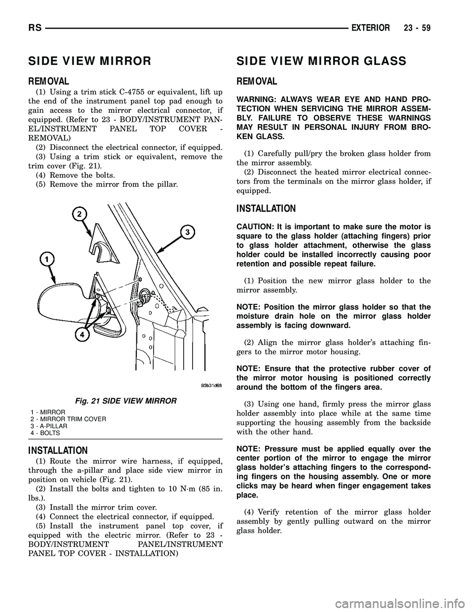
SIDE VIEW MIRROR
REMOVAL
(1) Using a trim stick C-4755 or equivalent, lift up
the end of the instrument panel top pad enough to
gain access to the mirror electrical connector, if
equipped. (Refer to 23 - BODY/INSTRUMENT PAN-
EL/INSTRUMENT PANEL TOP COVER -
REMOVAL)
(2) Disconnect the electrical connector, if equipped.
(3) Using a trim stick or equivalent, remove the
trim cover (Fig. 21).
(4) Remove the bolts.
(5) Remove the mirror from the pillar.
INSTALLATION
(1) Route the mirror wire harness, if equipped,
through the a-pillar and place side view mirror in
position on vehicle (Fig. 21).
(2) Install the bolts and tighten to 10 N´m (85 in.
lbs.).
(3) Install the mirror trim cover.
(4) Connect the electrical connector, if equipped.
(5) Install the instrument panel top cover, if
equipped with the electric mirror. (Refer to 23 -
BODY/INSTRUMENT PANEL/INSTRUMENT
PANEL TOP COVER - INSTALLATION)
SIDE VIEW MIRROR GLASS
REMOVAL
WARNING: ALWAYS WEAR EYE AND HAND PRO-
TECTION WHEN SERVICING THE MIRROR ASSEM-
BLY. FAILURE TO OBSERVE THESE WARNINGS
MAY RESULT IN PERSONAL INJURY FROM BRO-
KEN GLASS.
(1) Carefully pull/pry the broken glass holder from
the mirror assembly.
(2) Disconnect the heated mirror electrical connec-
tors from the terminals on the mirror glass holder, if
equipped.
INSTALLATION
CAUTION: It is important to make sure the motor is
square to the glass holder (attaching fingers) prior
to glass holder attachment, otherwise the glass
holder could be installed incorrectly causing poor
retention and possible repeat failure.
(1) Position the new mirror glass holder to the
mirror assembly.
NOTE: Position the mirror glass holder so that the
moisture drain hole on the mirror glass holder
assembly is facing downward.
(2) Align the mirror glass holder's attaching fin-
gers to the mirror motor housing.
NOTE: Ensure that the protective rubber cover of
the mirror motor housing is positioned correctly
around the bottom of the fingers area.
(3) Using one hand, firmly press the mirror glass
holder assembly into place while at the same time
supporting the housing assembly from the backside
with the other hand.
NOTE: Pressure must be applied equally over the
center portion of the mirror to engage the mirror
glass holder's attaching fingers to the correspond-
ing fingers on the housing assembly. One or more
clicks may be heard when finger engagement takes
place.
(4) Verify retention of the mirror glass holder
assembly by gently pulling outward on the mirror
glass holder.
Fig. 21 SIDE VIEW MIRROR
1 - MIRROR
2 - MIRROR TRIM COVER
3 - A-PILLAR
4 - BOLTS
RSEXTERIOR23-59
Page 2182 of 2585

INSTRUMENT PANEL TOP PAD
ASSEMBLY
REMOVAL
(1) Remove the instrument cluster (Fig. 14). (Refer
to 8 - ELECTRICAL/INSTRUMENT CLUSTER -
REMOVAL)
(2) Remove the message center (Fig. 14). (Refer to
8 - ELECTRICAL/MESSAGE CENTER - REMOVAL)
(3) Remove the radio (Fig. 14). (Refer to 8 - ELEC-
TRICAL/AUDIO/RADIO - REMOVAL)
(4) Remove the headlamp switch (Fig. 14). (Refer
to 8 - ELECTRICAL/LAMPS/LIGHTING - EXTERI-
OR/HEADLAMP SWITCH - REMOVAL)
(5) Remove the lower console (Fig. 14). (Refer to 23
- BODY/INSTRUMENT PANEL/LOWER CONSOLE
- REMOVAL)
(6) Remove the lower panel. (Refer to 23 - BODY/
INSTRUMENT PANEL/LOWER INSTRUMENT
PANEL TRIM - REMOVAL)
(7) Remove the instrument panel assembly. (Refer
to 23 - BODY/INSTRUMENT PANEL/INSTRUMENT
PANEL ASSEMBLY - REMOVAL)
(8) Remove the instrument panel speakers.
(9) Remove the glove box light.
(10) Remove the two passenger air bag mounting
bolts (Fig. 15).
(11) Loosen the three passenger air bag support
bracket bolts to the hydro-form rail (Fig. 15).
(12) Remove the 16 screws along the upper edge of
the pad & panel assembly.
(13) Remove the 19 screws along the lower edge of
the pad & panel assembly.
(14) Remove the pad and panel assembly (Fig. 14).
Fig. 13 OVER STEERING COLUMN COVER
1 - INSTRUMENT PANEL OVER STEERING COLUMN COVER
2 - INSTRUMENT PANEL
Fig. 14 INSTRUMENT PANEL ASSEMBLY
1 - INSTRUMENT CLUSTER
2 - MESSAGE CENTER
3 - TOP COVER
4 - PAD AND PANEL ASSEMBLY
5 - LOWER CONSOLE
6 - LOWER PANEL
7 - RADIO
8 - HEADLAMP SWITCH
Fig. 15 AIRBAG MOUNTING HARDWARE
1 - AIR BAG SCREWS (2)
2 - ELECTRICAL CONNECTOR
3 - AIR BAG SUPPORT BRACKET BOLTS (3)
4 - HYDRO-FORM INSTRUMENT PANEL SUPPORT RAIL
RSINSTRUMENT PANEL23-71
OVER STEERING COLUMN COVER (Continued)
Page 2183 of 2585

INSTALLATION
(1) Position the pad & panel assembly onto the
instrument panel support structure.
(2) Install the 19 screws along the lower edge of
the pad & panel assembly.
(3) Install the 16 screws along the upper edge of
the pad & panel assembly.
(4) Install and tighten the two passenger air bag
mounting screws.
(5) Tighten the three passenger air bag support
bracket bolts to the hydro-form tube.
(6) Install the glove box light.
(7) Install the instrument panel speakers.
(8) Install the instrument panel assembly. (Refer
to 23 - BODY/INSTRUMENT PANEL/INSTRUMENT
PANEL ASSEMBLY - INSTALLATION)
(9) Install the lower panel. (Refer to 23 - BODY/
INSTRUMENT PANEL/LOWER INSTRUMENT
PANEL TRIM - INSTALLATION)(10) Install the lower console. (Refer to 23 - BODY/
INSTRUMENT PANEL/LOWER CONSOLE -
INSTALLATION)
(11) Install the headlamp switch. (Refer to 8 -
ELECTRICAL/LAMPS/LIGHTING - EXTERIOR/
HEADLAMP SWITCH - INSTALLATION)
(12) Install the radio. (Refer to 8 - ELECTRICAL/
AUDIO/RADIO - INSTALLATION)
(13) Install the message center. (Refer to 8 -
ELECTRICAL/MESSAGE CENTER - INSTALLA-
TION)
(14) Install the instrument cluster. (Refer to 8 -
ELECTRICAL/INSTRUMENT CLUSTER - INSTAL-
LATION)
23 - 72 INSTRUMENT PANELRS
INSTRUMENT PANEL TOP PAD ASSEMBLY (Continued)