sensor CHRYSLER VOYAGER 2004 Repair Manual
[x] Cancel search | Manufacturer: CHRYSLER, Model Year: 2004, Model line: VOYAGER, Model: CHRYSLER VOYAGER 2004Pages: 2585, PDF Size: 62.54 MB
Page 477 of 2585
CHARGING
TABLE OF CONTENTS
page page
CHARGING DESCRIPTION - CHARGING SYSTEM .......20
OPERATION - CHARGING SYSTEM .........20
DIAGNOSIS AND TESTING - ON-BOARD DIAGNOSTIC SYSTEM .................21
SPECIFICATIONS GENERATOR ........................22
TORQUE ............................22
SPECIFICATIONS - BATTERY TEMPERATURE SENSOR ...............22
SPECIAL TOOLS .......................23
BATTERY TEMPERATURE SENSOR DESCRIPTION .........................23
OPERATION ...........................23
REMOVAL .............................23
GENERATOR DESCRIPTION .........................23
OPERATION ...........................23 REMOVAL
REMOVAL - 2.4L ......................23
REMOVAL - 2.5L ......................24
REMOVAL - 3.3/3.8L ...................25
INSTALLATION INSTALLATION - 2.4L ..................26
INSTALLATION - 2.5L ..................26
INSTALLATION - 3.3/3.8L ................26
GENERATOR DECOUPLER PULLEY DESCRIPTION .........................27
OPERATION ...........................27
DIAGNOSIS AND TESTING - GENERATOR DECOUPLER PULLEY ..................27
REMOVAL .............................28
INSTALLATION .........................28
VOLTAGE REGULATOR DESCRIPTION .........................29
OPERATION ...........................29
CHARGING
DESCRIPTION - CHARGING SYSTEM
The charging system consists of:
²Generator
² Decoupler Pulley (If equipped)
² Electronic Voltage Regulator (EVR) circuitry
within the Powertrain Control Module (PCM) ² Ignition switch (refer to the Ignition System sec-
tion for information) ² Battery (refer to the Battery section for informa-
tion) ² Ambient Air Temperature (If equipped)
² Inlet Air Temperature (calculated battery tem-
perature)(If equipped) ² Voltmeter (refer to the Instrument Cluster sec-
tion for information if equipped) ² Wiring harness and connections (refer to the
Wiring section for information) ² Accessory drive belt (refer to the Cooling section
for more information) ² Battery Temperature sensor (if equipped)
OPERATION - CHARGING SYSTEM
The charging system is turned on and off with the
ignition switch. The system is on when the engine is
running and the ASD relay is energized. The ASD
relay is energized when the PCM grounds the ASD
control circuit. This voltage is connected through the PCM or IPM (intelligent power module) (if equipped)
and supplied to one of the generator field terminals
(Gen. Source +) at the back of the generator.
The generator is driven by the engine through a
serpentine belt and pulley or decoupler pulley
arrangement. The amount of DC current produced by the gener-
ator is controlled by the EVR (field control) circuitry
contained within the PCM. This circuitry is con-
nected in series with the second rotor field terminal
and ground. An Ambient air temperature sensor is used to cal-
culate the temperature near the battery. This tem-
perature data, along with data from monitored line
voltage (battery voltage sense circuit), is used by the
PCM to vary the battery charging rate. This is done
by cycling the ground path to control the strength of
the rotor magnetic field. The PCM then compensates
and regulates generator current output accordingly
to maintain system voltage at the targeted system
voltage based on battery temperature. All vehicles are equipped with On-Board Diagnos-
tics (OBD). All OBD-sensed systems, including EVR
(field control) circuitry, are monitored by the PCM.
Each monitored circuit is assigned a Diagnostic Trou-
ble Code (DTC). The PCM will store a DTC in elec-
tronic memory for certain failures it detects and
illuminate the (MIL) lamp. Refer to On-Board Diag-
nostics in the Electronic Control Modules(Refer to 8 -
ELECTRICAL/ELECTRONIC CONTROL MOD-
8Fs - 20 CHARGINGRS
Page 478 of 2585
ULES/POWERTRAIN CONTROL MODULE -
DESCRIPTION) section for more DTC information.The Charging system ªBatteryº light indicates
problems with the charging system (voltage too high/
low, generator failure, etc.). If an extreme condition is
indicated, the lamp will be illuminated. The signal to
activate the lamp is sent via the PCI bus circuits.
The lamp is located on the instrument panel. Refer
to the Instrument Cluster section for additional infor-
mation. The PCM uses the ambient air temperature sensor
to control the charge system voltage. This tempera-
ture, along with data from monitored line voltage, is
used by the PCM to vary the battery charging rate.
The system voltage is higher at cold temperatures
and is gradually reduced as the calculated battery
temperature increases. The ambient temperature sensor is used to control
the battery voltage based upon ambient temperature
(approximation of battery temperature). The PCM
maintains the optimal output of the generator by
monitoring battery voltage and controlling it to a
range of 13.5 - 14.7 volts based on battery tempera-
ture.
DIAGNOSIS AND TESTING - ON-BOARD
DIAGNOSTIC SYSTEM
The Powertrain Control Module (PCM) monitors
critical input and output circuits of the charging sys-
tem, making sure they are operational. A Diagnostic
Trouble Code (DTC) is assigned to each input and
output circuit monitored by the OBD system. Some
circuits are checked continuously and some are
checked only under certain conditions. If the OBD system senses that a monitored circuit
is bad, it will put a DTC into electronic memory. The
DTC will stay in electronic memory as long as the
circuit continues to be bad. The PCM is programmed
to clear the memory after 40 good trip if the problem
does not occur again.
DIAGNOSTIC TROUBLE CODES
A DTC description can be read using the DRBIII t
scan tool. Refer to the appropriate Powertrain Diag-
nostic Procedures manual for information. A DTC does not identify which component in a cir-
cuit is bad. Thus, a DTC should be treated as a
symptom, not as the cause for the problem. In some
cases, because of the design of the diagnostic test
procedure, a DTC can be the reason for another DTC
to be set. Therefore, it is important that the test pro-
cedures be followed in sequence, to understand what
caused a DTC to be set. ERASING DIAGNOSTIC TROUBLE CODES
The DRBIII tScan Tool must be used to erase a
DTC. The following procedures may be used to diagnose
the charging system if: ² the check gauges lamp or battery lamp is illumi-
nated with the engine running ² the voltmeter (if equipped) does not register
properly ² an undercharged or overcharged battery condi-
tion occurs. Remember that an undercharged battery is often
caused by: ² accessories being left on with the engine not
running ² a faulty or improperly adjusted switch that
allows a lamp to stay on. Refer to Ignition-Off Draw
Test (Refer t o 8 - ELECTRICAL/BATTERY SYSTEM/
BATTERY - STANDARD PROCEDURE) ² loose generator belt.
INSPECTION The Powertrain Control Module (PCM) monitors
critical input and output circuits of the charging sys-
tem, making sure they are operational. A Diagnostic
Trouble Code (DTC) is assigned to each input and
output circuit monitored by the On-Board Diagnostic
(OBD) system. Some charging system circuits are
checked continuously, and some are checked only
under certain conditions. Refer to Diagnostic Trouble Codes in; Powertrain
Control Module; Electronic Control Modules for more
DTC information. This will include a complete list of
DTC's including DTC's for the charging system. To perform a complete test of the charging system,
refer to the appropriate Powertrain Diagnostic Proce-
dures service manual and the DRBIII tscan tool.
Perform the following inspections before attaching
the scan tool. (1) Inspect the battery condition. Refer to the Bat-
tery section (Refer t o 8 - ELECTRICAL/BATTERY
SYSTEM - DIAGNOSIS AND TESTING) for proce-
dures. (2) Inspect condition of battery cable terminals,
battery posts, connections at engine block, starter
solenoid and relay. They should be clean and tight.
Repair as required. (3) Inspect all fuses in both the fuseblock and
Power Distribution Center (PDC) or IPM (if
equipped) for tightness in receptacles. They should be
properly installed and tight. Repair or replace as
required. (4) Inspect generator mounting bolts for tightness.
Replace or tighten bolts if required. Refer to the Gen-
erator Removal/Installation section of this group for
RS CHARGING8Fs-21
CHARGING (Continued)
Page 479 of 2585

torque specifications (Refer to 8 - ELECTRICAL/
CHARGING - SPECIFICATIONS). (5) Inspect generator drive belt condition and ten-
sion. Tighten or replace belt as required. Refer to
Belt Tension Specifications(Refer t o 7 - COOLING/
ACCESSORY DRIVE - SPECIFICATIONS). (6) Inspect decoupler pulley (if equipped). Ensure
decoupler pulley is driving the alternator rotor. (7) Inspect automatic belt tensioner (if equipped).
Refer to the Cooling System for more information. (8) Inspect generator electrical connections at gen-
erator field, battery output, and ground terminal (if
equipped). Also check generator ground wire connec-
tion at engine (if equipped). They should all be clean
and tight. Repair as required.SPECIFICATIONS
GENERATOR
Type Engine Minimun Test Amperage
Denso 2.4 L 80 Amp (HOT)
Denso 3.3/3.8L 100 Amp or 115 Amp (HOT)
Test Specification:
1. Engine RPM : 2500 RPM 20 RPM (HOT)
2. Voltage Output : 14. 0 V 0.5 V
3. Field Curren t : 5 amps 0.1 amps
Part number is located on the side of the generator.
TORQUE
DESCRIPTION N´m Ft. Lbs. In. Lbs.
Battery Hold Down Clamp Bolt 20 14.7 180
Generator B+ Nut 12.4 9.2 110
Battery Terminal Nut 4 35
Generator Mounting Bolt 2.4L 28.2 20.8 250
Generator Mounting Bolts 3.3/3.8L 54.2 40
Starter Solenoid Battery Nut 3.3/3.8L 11.3 8.3 100
Generator Decoupler 109.8 81
SPECIFICATIONS - BATTERY TEMPERATURE
SENSOR
ÉC ÉF K-Ohms Min. K-Ohms Max.
(40) (40) 291.4 381.7
(20) (4) 85.8 108.4 20 68 11.4 13.6
25 77 9.1 10.9
120 248 0.37 0.41
130 266 0.28 0.32
8Fs - 22 CHARGINGRS
CHARGING (Continued)
Page 480 of 2585
SPECIAL TOOLS
BATTERY TEMPERATURE
SENSOR
DESCRIPTION
(NGC Vehicles) The PCM incorporates a Battery
Temperature Sensor (BTS) on its circuit board.
OPERATION
The PCM uses the temperature of the battery area
to control the charge system voltage. This tempera-
ture, along with data from monitored line voltage, is
used by the PCM to vary the battery charging rate.
The system voltage is higher at cold temperatures
and is gradually reduced as temperature around the
battery increases. For vehicles with 1.6L engine, there is no physical
battery temp sensor in place to detect battery temp.
Rather, an algorithm buit in PCM is employed to pre-
dict battery temp using inlet air temp, vehicle speed,
and coolant temp, among other signals. The PCM
maintains the optimal output of the generator by
monitoring battery voltage and controlling it to a
range of 13.5 - 14.7 volts based on battery tempera-
ture. The system target voltage is 13.5 ± 14.7 volts.
However the actual voltage go below this during
heavy electrical loads and generator speeds. Also the
actual voltage can be lower than the target voltage
between the battery and the battery voltage sense
circuit, approximately 0.2 Ð 0.3 volts. The battery temperature sensor is also used for
OBD II diagnostics. Certain faults and OBD II mon-
itors are either enabled or disabled depending upon
the battery temperature sensor input (example: dis-
able purge and EGR, enable LDP). Most OBD II
monitors are disabled below 20ÉF.
REMOVAL
The battery temperature sensor is not serviced sep-
arately. If replacement is necessary, the PCM must
be replaced.
GENERATOR
DESCRIPTION
The generator is belt-driven by the engine. The
generator produces DC voltage at the B+ terminal. If
the generator is failed, the generator assembly sub-
components (generator and decoupler pulley) must be
inspected for individual failure and replaced accord-
ingly.
OPERATION
As the energized rotor begins to rotate within the
generator, the spinning magnetic field induces a cur-
rent into the windings of the stator coil. Once the
generator begins producing sufficient current, it also
provides the current needed to energize the rotor. The Y type stator winding connections deliver the
induced AC current to 3 positive and 3 negative
diodes for rectification. From the diodes, rectified DC
current is delivered to the vehicles electrical system
through the generator, battery, and ground terminals. Excessive or abnormal noise emitting from the gen-
erator may be caused by: ² Worn, loose or defective bearings
² Loose or defective drive pulley (2.4L) or decou-
pler (3.3/3.8L) ² Incorrect, worn, damaged or misadjusted drive
belt ² Loose mounting bolts
² Misaligned drive pulley
² Defective stator or diode
² Damaged internal fins
REMOVAL
REMOVAL - 2.4L
(1) Release hood latch and open hood.
(2) Disconnect battery negative cable.
(3) Disconnect the Inlet Air Temperature sensor.
(4) Remove the Air Box, refer to the Engine/Air
Cleaner for more information. (5) Remove the EVAP Purge solenoid from its
bracket and reposition. (6) Disconnect the push-in field wire connector
from back of generator. (7) Remove nut holding B+ wire terminal to back
of generator. (8) Separate B+ terminal from generator.
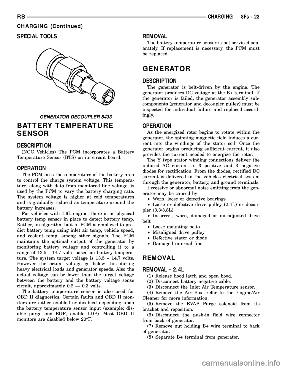
GENERATOR DECOUPLER 8433
RS CHARGING8Fs-23
CHARGING (Continued)
Page 483 of 2585
(11) Remove the 3 mounting bolts.
(12) Lower vehicle.
(13) Remove oil dip stick tube from vehicle.
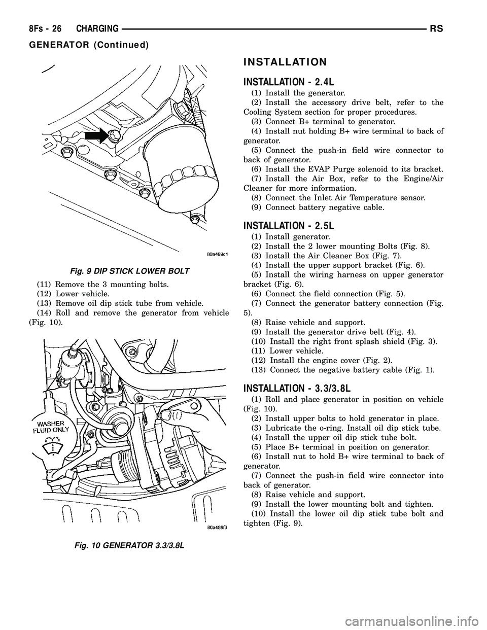
(14) Roll and remove the generator from vehicle
(Fig. 10).
INSTALLATION
INSTALLATION - 2.4L
(1) Install the generator.
(2) Install the accessory drive belt, refer to the
Cooling System section for proper procedures. (3) Connect B+ terminal to generator.
(4) Install nut holding B+ wire terminal to back of
generator. (5) Connect the push-in field wire connector to
back of generator. (6) Install the EVAP Purge solenoid to its bracket.
(7) Install the Air Box, refer to the Engine/Air
Cleaner for more information. (8) Connect the Inlet Air Temperature sensor.
(9) Connect battery negative cable.
INSTALLATION - 2.5L
(1) Install generator.
(2) Install the 2 lower mounting Bolts (Fig. 8).
(3) Install the Air Cleaner Box (Fig. 7).
(4) Install the upper support bracket (Fig. 6).
(5) Install the wiring harness on upper generator
bracket (Fig. 6). (6) Connect the field connection (Fig. 5).
(7) Connect the generator battery connection (Fig.
5). (8) Raise vehicle and support.
(9) Install the generator drive belt (Fig. 4).
(10) Install the right front splash shield (Fig. 3).
(11) Lower vehicle.
(12) Install the engine cover (Fig. 2).
(13) Connect the negative battery cable (Fig. 1).
INSTALLATION - 3.3/3.8L
(1) Roll and place generator in position on vehicle
(Fig. 10). (2) Install upper bolts to hold generator in place.
(3) Lubricate the o-ring. Install oil dip stick tube.
(4) Install the upper oil dip stick tube bolt.
(5) Place B+ terminal in position on generator.
(6) Install nut to hold B+ wire terminal to back of
generator. (7) Connect the push-in field wire connector into
back of generator. (8) Raise vehicle and support.
(9) Install the lower mounting bolt and tighten.
(10) Install the lower oil dip stick tube bolt and
tighten (Fig. 9).
Fig. 9 DIP STICK LOWER BOLT
Fig. 10 GENERATOR 3.3/3.8L
8Fs - 26 CHARGINGRS
GENERATOR (Continued)
Page 486 of 2585
VOLTAGE REGULATOR
DESCRIPTION
The Electronic Voltage Regulator (EVR) is not a
separate component. It is actually a voltage regulat-
ing circuit located within the Powertrain Control
Module (PCM). The EVR is not serviced separately. If
replacement is necessary, the PCM must be replaced.
OPERATION
The amount of DC current produced by the gener-
ator is controlled by EVR circuitry contained within
the PCM. This circuitry is connected in series with
the generators second rotor field terminal and its
ground. Voltage is regulated within the PCM on the NGC
vehicles, to control the strength of the rotor magnetic
field. The EVR circuitry monitors system line voltage
at the PDC and calculated battery temperature or
inlet air temperature sensor (refer to Inlet Air Tem-
perature Sensor, if equipped, for more information ).
It then determines a target charging voltage. If
sensed battery voltage is lower than the target volt-
age, the PCM feeds the field winding until sensed
battery voltage is at the target voltage. A circuit in
the PCM cycles the feed side of the generator field at
250 times per second (250Hz), but has the capability
to feed the field control wire 100% of the time (full
field) to achieve the target voltage. If the charging
rate cannot be monitored (limp-in), a duty cycle of
20% is used by the PCM in order to have some gen-
erator output. Also refer to Charging System Opera-
tion for additional information.
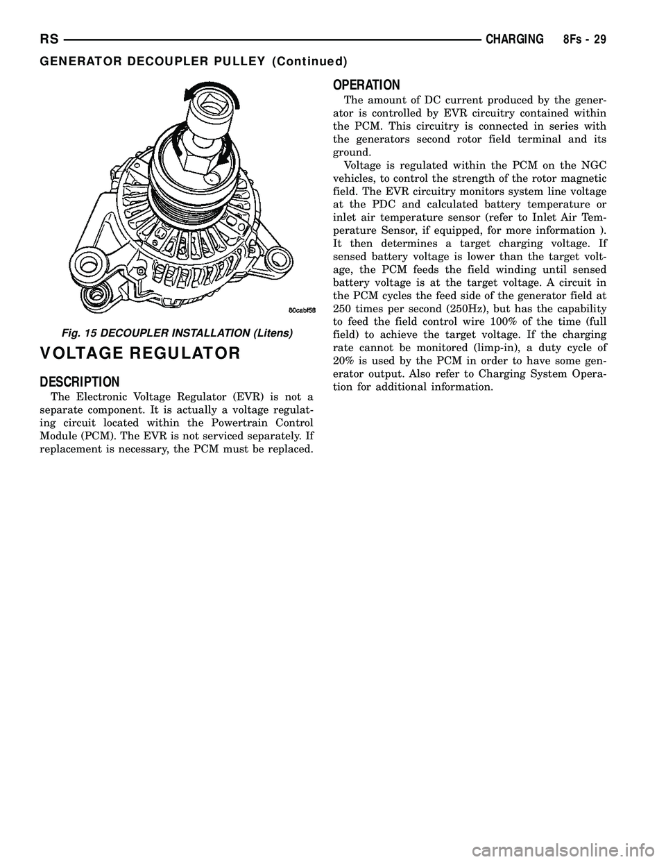
Fig. 15 DECOUPLER INSTALLATION (Litens)
RS CHARGING8Fs-29
GENERATOR DECOUPLER PULLEY (Continued)
Page 488 of 2585
the battery, if required. Refer to the Battery section
for more information.² Ignition Switch - Visually inspect the ignition
switch for indications of physical damage and loose
or corroded wire harness connections. ² Transmission Range Sensor or Park/Neu-
tral Switch - Visually inspect the transmission
range sensor for indications of physical damage and
loose or corroded wire harness connections. ² Starter Relay - Visually inspect the starter
relay for indications of physical damage and loose or
corroded wire harness connections. ² Starter Motor - Visually inspect the starter
motor for indications of physical damage and loose or
corroded wire harness connections. ²
Starter Solenoid - Visually inspect the starter
solenoid for indications of physical damage and loose
or corroded wire harness connections. ² Wiring - Visually inspect the wire harness for
damage. Repair or replace any faulty wiring, as
required. Check for loose or corroded wire harness
connections at main engine ground and remote jump
post. ² Power Distribution Center (PDC) - Visually
inspect the B+ connections at the PDC for physical
damage and loose or corroded harness connections.
STARTING SYSTEM DIAGNOSIS
CONDITION POSSIBLE CAUSE CORRECTION
STARTER FAILS
TO ENGAGE. 1. BATTERY
DISCHARGED OR
FAULTY. 1. REFER TO THE BATTERY SECTION FOR MORE
INFORMATION. CHARGE OR REPLACE BATTERY, IF
REQUIRED.
2. STARTING CIRCUIT
WIRING FAULTY. 2. REFER TO FEED CIRCUIT RESISTANCE TEST AND FEED
CIRCUIT TEST IN THIS SECTION.
3. STARTER RELAY
FAULTY. 3. REFER TO RELAY TEST, IN THIS SECTION. REPLACE
RELAY, IF NECESSARY.
4. IGNITION SWITCH
FAULTY. 4. REFER TO IGNITION SWITCH TEST, IN THE STEERING
SECTION OR 8 WIRING DIAGRAMS. REPLACE SWITCH, IF
NECESSARY.
5. PARK/NEUTRAL
POSITION SWITCH
(AUTO TRANS) FAULTY
OR MIS-ADJUSTED. 5. REFER PARK/NEUTRAL POSITION SWITCH TEST, IN THE
TRANSAXLE. SECTION FOR MORE INFORMATION. REPLACE
SWITCH, IF NECESSARY.
6. CLUTCH INTERLOCK
SWITCH (MAN TRANS)
FAULTY. 6. REFER TO CLUTCH PEDAL POSITION SWITCH TEST, IN
THE CLUTCH. SECTION. REPLACE SWITCH, IF NECESSARY.
7. STARTER SOLENOID
FAULTY. 7. REFER TO SOLENOID TEST, IN THIS SECTION. REPLACE
STARTER ASSEMBLY, IF NECESSARY.
8. STARTER ASSEMBLY
FAULTY. 8. IF ALL OTHER STARTING SYSTEM COMPONENTS AND
CIRCUITS CHECK OK, REPLACE STARTER ASSEMBLY.
9. FAULTY TEETH ON
RING GEAR. 9. ROTATE FLYWHEEL 360É, AND INSPECT TEETH AND RING
GEAR REPLACED IF DAMAGED.
10. PCM DOUBLE
START OVERRIDE
OUTPUT FAILURE. 10. REFER TO PCM DIAGNOSTIC. CHECK FOR CONTINUITY
BETWEEN PCM AND TERMINAL 85. REPAIR OPEN CIRCUIT
AS REQUIRED. IF OK, PCM MAY BE DEFECTIVE.
STARTER
ENGAGES,
FAILS TO TURN
ENGINE. 1. BATTERY
DISCHARGED OR
FAULTY.
1. REFER TO THE BATTERY SECTION FOR MORE
INFORMATION. CHARGE OR REPLACE BATTERY AS
NECESSARY.
RS
STARTING8Fs-31
STARTING (Continued)
Page 489 of 2585

CONDITION POSSIBLE CAUSE CORRECTION2. STARTING CIRCUIT
WIRING FAULTY. 2. REFER TO THE FEED CIRCUIT RESISTANCE TEST AND
THE FEED CIRCUIT TEST IN THIS SECTION. REPAIR AS
NECESSARY.
3. STARTER ASSEMBLY
FAULTY. 3. IF ALL OTHER STARTING SYSTEM COMPONENTS AND
CIRCUITS CHECK OK, REPLACE STARTER ASSEMBLY.
4. ENGINE SEIZED. 4. REFER TO THE ENGINE SECTION, FOR DIAGNOSTIC AND SERVICE PROCEDURES.
5. LOOSE
CONNECTION AT
BATTERY, PDC,
STARTER, OR ENGINE
GROUND. 5. INSPECT FOR LOOSE CONNECTIONS.
6. FAULTY TEETH ON
RING GEAR. 6. ROTATE FLYWHEEL 360É, AND INSPECT TEETH AND RING
GEAR REPLACED IF DAMAGED.
STARTER
ENGAGES,
SPINS OUT
BEFORE
ENGINE
STARTS. 1. BROKEN TEETH ON
STARTER RING GEAR.
1. REMOVE STARTER. INSPECT RING GEAR AND REPLACE
IF NECESSARY.
2. STARTER ASSEMBLY
FAULTY. 2. IF ALL OTHER STARTING SYSTEM COMPONENTS AND
CIRCUITS CHECK OK, REPLACE STARTER ASSEMBLY.
STARTER DOES
NOT
DISENGAGE. 1. STARTER
IMPROPERLY
INSTALLED. 1. INSTALL STARTER. TIGHTEN STARTER MOUNTING
HARDWARE TO CORRECT TORQUE SPECIFICATIONS.
2. STARTER RELAY
FAULTY. 2. REFER TO RELAY TEST, IN THIS SECTION. REPLACE
RELAY, IF NECESSARY.
3. IGNITION SWITCH
FAULTY. 3. REFER TO IGNITION SWITCH TEST, IN THE STEERING
SECTION. REPLACE SWITCH, IF NECESSARY.
4. STARTER ASSEMBLY
FAULTY. 4. IF ALL OTHER STARTING SYSTEM COMPONENTS AND
CIRCUITS CHECK OK, REPLACE STARTER ASSEMBLY.
5. FAULTY TEETH ON
RING GEAR. 5. ROTATE FLYWHEEL 360É, AND INSPECT TEETH AND RING
GEAR REPLACED IF DAMAGED.
DIAGNOSIS AND TESTING - CONTROL
CIRCUIT TEST
The starter control circuit has:
²
Starter motor with integral solenoid
² Starter relay
² Transmission range sensor, or Park/Neutral
Position switch with automatic transmissions ² Ignition switch
² Battery
² All related wiring and connections
² Powertrain Control Module (PCM)
CAUTION: Before performing any starter tests, the
ignition and fuel systems must be disabled. ²
To disable ignition and fuel systems, disconnect
the Automatic Shutdown Relay (ASD). The ASD relay
is located in the Power Distribution Center (PDC).
Refer to the PDC cover for the proper relay location.
STARTER SOLENOID
WARNING: CHECK TO ENSURE THAT THE TRANS-
MISSION IS IN THE PARK POSITION WITH THE
PARKING BRAKE APPLIED. THIS MAY RESULT IN
PERSONAL INJURY OR DEATH.
(1) Verify battery condition. Battery must be in
good condition with a full charge before performing
any starter tests. Refer to Battery Tests.
8Fs - 32 STARTINGRS
STARTING (Continued)
Page 491 of 2585

(2) The relay normally closed terminal (87A) is
connected to terminal 30 in the de-energized position,
but is not used for this application. Go to Step 3. (3) The relay normally open terminal (87) is con-
nected to the common feed terminal (30) in the ener-
gized position. This terminal supplies battery voltage
to the starter solenoid field coils. There should be
continuity between the cavity for relay terminal 87
and the starter solenoid terminal at all times. If OK,
go to Step 4. If not OK, repair the open circuit to the
starter solenoid as required. (4) The coil battery terminal (85) is connected to
the electromagnet in the relay. It is energized when
the ignition switch is held in the Start position and
the clutch pedal is depressed (manual trans). Check
for battery voltage at the cavity for relay terminal 86
with the ignition switch in the Start position and the
clutch pedal is depressed (manual trans), and no
voltage when the ignition switch is released to the
On position. If OK, go to Step 5. If not OK, check for
an open or short circuit to the ignition switch and
repair, if required. If the circuit to the ignition switch
is OK, see the Ignition Switch Test procedure in this
group. (5) The coil ground terminal (86) is connected to
the electromagnet in the relay. It is grounded by the
PCM if the conditions are right to start the car. For
automatic trans. cars the PCM must see Park Neu-
tral switch low and near zero engine speed (rpm).
For manual trans. cars the PCM only needs to see
near zero engine speed (rpm) and low clutch inter-
lock input and see near zero engine speed (rpm). To
diagnose the Park Neutral switch of the trans range
sensor refer to the transaxle section. Check for conti-
nuity to ground while the ignition switch is in the
start position and if equipped the clutch pedal
depressed. If not OK and the vehicle has an auto-
matic trans. verify Park Neutral switch operation. If
that checks OK check for continuity between PCM
and the terminal 86. Repair open circuit as required.
Also check the clutch interlock switch operation if
equipped with a manual transmission. If OK, the
PCM may be defective.
SAFETY SWITCHES
For diagnostics of the Transmission Range Sensor,
refer to the Transaxle section for more information. If equipped with Clutch Interlock/Upstop Switch,
refer to Diagnosis and Testing in the Clutch section.
IGNITION SWITCH
After testing starter solenoid and relay, test igni-
tion switch and wiring. Refer to the Ignition Section
or Wiring Diagrams for more information. Check all
wiring for opens or shorts, and all connectors for
being loose or corroded.
BATTERY
For battery diagnosis and testing, refer to the Bat-
tery section for procedures.
ALL RELATED WIRING AND CONNECTORS
Refer to Wiring Diagrams for more information.
DIAGNOSIS AND TESTING - FEED CIRCUIT
RESISTANCE TEST
Before proceeding with this operation, review Diag-
nostic Preparation and Starter Feed Circuit Tests.
The following operation will require a voltmeter,
accurate to 1/10 of a volt.
CAUTION: Ignition and Fuel systems must be dis-
abled to prevent engine start while performing the
following tests.
(1) To disable the Ignition and Fuel systems, dis-
connect the Automatic Shutdown Relay (ASD). The
ASD relay is located in the Power Distribution Cen-
ter (PDC). Refer to the PDC cover for proper relay
location. (2) Gain access to battery terminals.
(3) With all wiring harnesses and components
properly connected, perform the following: (a) Connect the negative lead of the voltmeter to
the battery negative post, and positive lead to the
battery negative cable clamp. Rotate and hold the
ignition switch in the START position. Observe the
voltmeter. If voltage is detected, correct poor con-
tact between cable clamp and post. (b) Connect positive lead of the voltmeter to the
battery positive post, and negative lead to the bat-
tery positive cable clamp. Rotate and hold the igni-
tion switch key in the START position. Observe the
voltmeter. If voltage is detected, correct poor con-
tact between the cable clamp and post. (c) Connect negative lead of voltmeter to battery
negative terminal, and positive lead to engine
block near the battery cable attaching point.
Rotate and hold the ignition switch in the START
position. If voltage reads above 0.2 volt, correct
poor contact at ground cable attaching point. If
voltage reading is still above 0.2 volt after correct-
ing poor contacts, replace ground cable.
(4) Connect positive voltmeter lead to the starter
motor housing and the negative lead to the battery
negative terminal. Hold the ignition switch key in
the START position. If voltage reads above 0.2 volt,
correct poor starter to engine ground. (a) Connect the positive voltmeter lead to the
battery positive terminal, and negative lead to bat-
tery cable terminal on starter solenoid. Rotate and
hold the ignition switch in the START position. If
voltage reads above 0.2 volt, correct poor contact at
8Fs - 34 STARTINGRS
STARTING (Continued)
Page 499 of 2585
(2) Position the rear window defogger relay into
the proper receptacle in the IPM.
(3) Align the rear window defogger relay terminals
with the terminal cavities in the IPM receptacle.
(4) Push down firmly on the rear window defogger
relay until the terminals are fully seated in the ter-
minal cavities in the IPM receptacle.
(5) Install the cover onto the IPM.
(6) Reconnect the battery negative cable.
REAR WINDOW DEFOGGER
SWITCH
DESCRIPTION
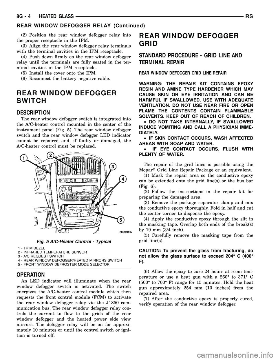
The rear window defogger switch is integrated into
the A/C-heater control mounted in the center of the
instrument panel (Fig. 5). The rear window defogger
switch and the rear window defogger LED indicator
cannot be repaired and, if faulty or damaged, the
A/C-heater control must be replaced.
OPERATION
An LED indicator will illuminate when the rear
window defogger switch is activated. The switch
energizes the A/C-heater control module which then
requests the front control module (FCM) to activate
the rear window defogger relay via the J1850 com-
munication bus. The rear window defogger relay con-
trols the current to flow to the grids of the rear
window defogger and the heated power side view
mirrors. The defogger relay will be on for approxi-
mately 10 minutes or until the control switch or igni-
tion is turned off.
REAR WINDOW DEFOGGER
GRID
STANDARD PROCEDURE - GRID LINE AND
TERMINAL REPAIR
REAR WINDOW DEFOGGER GRID LINE REPAIR
WARNING: THE REPAIR KIT CONTAINS EPOXY
RESIN AND AMINE TYPE HARDENER WHICH MAY
CAUSE SKIN OR EYE IRRITATION AND CAN BE
HARMFUL IF SWALLOWED. USE WITH ADEQUATE
VENTILATION. DO NOT USE NEAR FIRE OR OPEN
FLAME THE CONTENTS CONTAIN FLAMMABLE
SOLVENTS. KEEP OUT OF REACH OF CHILDREN.
²DO NOT TAKE INTERNALLY, IF SWALLOWED
INDUCE VOMITING AND CALL A PHYSICIAN IMME-
DIATELY.
²IF SKIN CONTACT OCCURS, WASH AFFECTED
AREAS WITH SOAP AND WATER.
²IF EYE CONTACT OCCURS, FLUSH WITH
PLENTY OF WATER.
The repair of the grid lines is possible using the
MopartGrid Line Repair Package or an equivalent.
(1) Mask the repair area so the conductive epoxy
can be extended onto the grid line(s) or the bus bar
(Fig. 6).
(2) Follow the instructions in the repair kit for
preparing the damaged area.
(3) Remove the package separator clamp and mix
the conductive epoxy thoroughly. Fold in half and cut
the center corner to dispense the epoxy.
(4) Apply the conductive epoxy through the slit in
the masking tape. Overlap both ends of the break(s)
by 19 mm (3/4 inch).
(5) Carefully remove the masking tape from the
grid line(s).
CAUTION: To prevent the glass from fracturing, do
not allow the glass surface to exceed 204É C (400É
F).
(6) Allow the epoxy to cure 24 hours at room tem-
perature or use a heat gun with a 260É to 371É C
(500É to 700É F) range for 15 minutes. Hold the heat
gun approximately 254 mm (10 inches) from the
repaired area.
(7) After the conductive epoxy is properly cured,
verify operation of the rear window defogger.
Fig. 5 A/C-Heater Control - Typical
1 - TRIM BEZEL
2 - INFRARED TEMPERATURE SENSOR
3 - A/C REQUEST SWITCH
4 - REAR WINDOW DEFOGGER/HEATED MIRRORS SWITCH
5 - FRONT WINDOW DEFROSTER MODE SELECTOR
8G - 4 HEATED GLASSRS
REAR WINDOW DEFOGGER RELAY (Continued)