OUTLET CHRYSLER VOYAGER 2004 Manual PDF
[x] Cancel search | Manufacturer: CHRYSLER, Model Year: 2004, Model line: VOYAGER, Model: CHRYSLER VOYAGER 2004Pages: 2585, PDF Size: 62.54 MB
Page 1592 of 2585

CAUTION: When tightening and torquing the pres-
sure hose at the power steering pump, the pressurehose is to be rotated against the fluid return hose
fitting on the pump.
(8) Tighten pressure hose tube nuts at pump and
gear to 31 N´m (275 in. lbs.) torque.
(9) Install front emissions vapor canister. (Refer to
25 - EMISSIONS CONTROL/EVAPORATIVE EMIS-
SIONS/VAPOR CANISTER - INSTALLATION)
(10) Lower vehicle.
(11) Fill and bleed the power steering system
using the Power Steering Pump Initial Operation
Procedure. (Refer to 19 - STEERING/PUMP - STAN-
DARD PROCEDURE)
(12) Inspect system for leaks.
INSTALLATION - 3.3L/3.8L ENGINE
(1) Remove any used O-rings from ends of power
steering hose.
(2) Using a lint free towel, wipe clean hose ends,
power steering pump pressure outlet fitting and
steering gear port.
(3) Install new O-rings on ends of power steering
fluid pressure hose. Lubricate O-rings using clean
power steering fluid.
Fig. 21 RESERVOIR AND HOSES - 3.3L/3.8L
1 - RESERVOIR
2 - ROUTING CLIP (2001 ONLY)
3 - SUPPLY HOSE
4 - POWER STEERING PUMP5 - PRESSURE HOSE (TO GEAR)
6 - ROUTING BRACKET
7 - RETURN HOSE (FROM GEAR)
Fig. 22 PRESSURE HOSE ROUTING CLAMP
1 - PRESSURE HOSE TUBE
2 - STEERING GEAR
3 - CRADLE CROSSMEMBER
4 - DRIVESHAFT
5 - ROUTING CLAMP BRACKET
RSPUMP19-47
HOSE - POWER STEERING PRESSURE (Continued)
Page 1593 of 2585

CAUTION: Use care not to bend tube ends of the
power steering hoses when installing. Leaks and
restrictions may occur.
CAUTION: Power steering fluid hoses must remain
away from the exhaust system and must not come
in contact with any unfriendly surfaces on the vehi-
cle.
(4) Route hose up behind engine toward pump
avoiding tight bends or kinking.
(5) Install power steering pressure hose end into
pump pressure outlet fitting (Fig. 21). Thread tube
nut into outlet fitting, but do not tighten at this time.
(6) Attach pressure hose routing bracket to engine
(Fig. 21). Tighten bolt to 23 N´m (200 in. lbs.) torque.
(7) Tighten hose tube nut at pump outlet fitting to
31 N´m (275 in. lbs.) torque.
(8) Route hose behind cradle crossmember and
start hose end into gear port. Do not tighten hose
tube nut at this time.
(9) Attach hose to suspension cradle crossmember
and steel reinforcement using two routing clamps
and bolts (Fig. 20). Tighten clamp bolt at steel rein-
forcement to 11 N´m (100 in. lbs.) torque. Tighten
clamp bolt at cradle crossmember to 23 N´m (200 in.
lbs.) torque.
(10) Tighten hose tube nut at power steering gear
port to 31 N´m (275 in. lbs.) torque.
(11) Install front emissions vapor canister. (Refer
to 25 - EMISSIONS CONTROL/EVAPORATIVE
EMISSIONS/VAPOR CANISTER - INSTALLATION)
(12) Lower vehicle.
(13) Fill and bleed the power steering system
using the Power Steering Pump Initial Operation
Procedure. (Refer to 19 - STEERING/PUMP - STAN-
DARD PROCEDURE)
(14) Inspect system for leaks.
HOSE - POWER STEERING
RETURN
REMOVAL
REMOVAL - 2.4L ENGINE
NOTE: Before proceeding, review all WARNINGS
and CAUTIONS. (Refer to 19 - STEERING/PUMP -
WARNING)(Refer to 19 - STEERING/PUMP - CAU-
TION)
(1) Remove cap from power steering fluid reser-
voir.(2) Using a siphon pump, remove as much power
steering fluid as possible from power steering fluid
reservoir.
(3) Raise vehicle. (Refer to LUBRICATION &
MAINTENANCE/HOISTING - STANDARD PROCE-
DURE)
(4) Remove front emissions vapor canister. (Refer
to 25 - EMISSIONS CONTROL/EVAPORATIVE
EMISSIONS/VAPOR CANISTER - REMOVAL)
(5) Place an oil drain pan under vehicle to catch
power steering fluid.
(6) Cut tie-strap securing insulating heat sleeve to
power steering fluid return hose near power steering
pump. Pull back heat sleeve to expose hose clamp.
(7) Remove clamp, then return hose from power
steering pump (Fig. 19).
(8) Remove 2 bolts attaching power steering cooler
to cradle crossmember reinforcement (Fig. 23).
(9) Remove bolts attaching routing clamps to front
suspension cradle crossmember (Fig. 19). Remove
return hose from clamps.
(10) Back out return hose tube nut at power steer-
ing gear and remove hose (Fig. 19).
REMOVAL - 3.3L/3.8L ENGINE
NOTE: Before proceeding, review all WARNINGS
and CAUTIONS. (Refer to 19 - STEERING/PUMP -
WARNING)(Refer to 19 - STEERING/PUMP - CAU-
TION)
(1) Remove cap from power steering fluid reser-
voir.
(2) Using a siphon pump, remove as much power
steering fluid as possible from power steering fluid
reservoir.
(3) Place an oil drain pan under vehicle to catch
any draining power steering fluid.
(4) Remove clamp attaching return hose to power
steering fluid reservoir. Disconnect hose from reser-
voir (Fig. 21).
(5) Follow return hose downward and open
retainer at ABS bracket (Fig. 20). Remove hose tube
from retainer.
(6) Raise vehicle. (Refer to LUBRICATION &
MAINTENANCE/HOISTING - STANDARD PROCE-
DURE)
(7) Remove front emissions vapor canister. (Refer
to 25 - EMISSIONS CONTROL/EVAPORATIVE
EMISSIONS/VAPOR CANISTER - REMOVAL)
(8) Remove bolt securing return hose routing
clamp to suspension cradle crossmember (Fig. 20).
(9) Remove 2 bolts attaching power steering cooler
to cradle crossmember reinforcement (Fig. 23).
(10) Disconnect return hose at power steering gear
(Fig. 20).
19 - 48 PUMPRS
HOSE - POWER STEERING PRESSURE (Continued)
Page 1827 of 2585
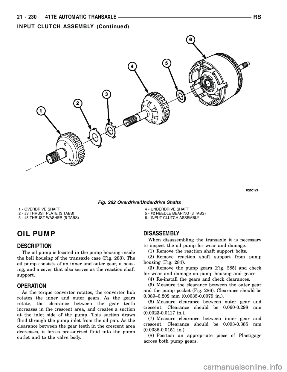
OIL PUMP
DESCRIPTION
The oil pump is located in the pump housing inside
the bell housing of the transaxle case (Fig. 283). The
oil pump consists of an inner and outer gear, a hous-
ing, and a cover that also serves as the reaction shaft
support.
OPERATION
As the torque converter rotates, the converter hub
rotates the inner and outer gears. As the gears
rotate, the clearance between the gear teeth
increases in the crescent area, and creates a suction
at the inlet side of the pump. This suction draws
fluid through the pump inlet from the oil pan. As the
clearance between the gear teeth in the crescent area
decreases, it forces pressurized fluid into the pump
outlet and to the valve body.
DISASSEMBLY
When disassembling the transaxle it is necessary
to inspect the oil pump for wear and damage.
(1) Remove the reaction shaft support bolts.
(2) Remove reaction shaft support from pump
housing (Fig. 284).
(3) Remove the pump gears (Fig. 285) and check
for wear and damage on pump housing and gears.
(4) Re-install the gears and check clearances.
(5) Measure the clearance between the outer gear
and the pump pocket (Fig. 286). Clearance should be
0.089±0.202 mm (0.0035-0.0079 in.).
(6) Measure clearance between outer gear and
crescent. Clearance should be 0.060-0.298 mm
(0.0023-0.0117 in.).
(7) Measure clearance between inner gear and
crescent. Clearance should be 0.093-0.385 mm
(0.0036-0.0151 in.).
(8) Position an appropriate piece of Plastigage
across both pump gears.
Fig. 282 Overdrive/Underdrive Shafts
1 - OVERDRIVE SHAFT
2 - #3 THRUST PLATE (3 TABS)
3 - #3 THRUST WASHER (5 TABS)4 - UNDERDRIVE SHAFT
5 - #2 NEEDLE BEARING (3 TABS)
6 - INPUT CLUTCH ASSEMBLY
21 - 230 41TE AUTOMATIC TRANSAXLERS
INPUT CLUTCH ASSEMBLY (Continued)
Page 1992 of 2585
OIL PUMP
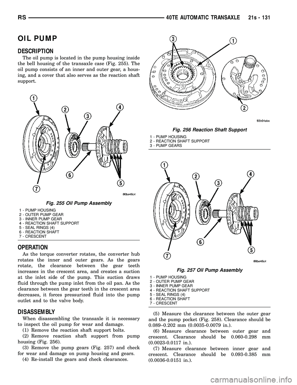
DESCRIPTION
The oil pump is located in the pump housing inside
the bell housing of the transaxle case (Fig. 255). The
oil pump consists of an inner and outer gear, a hous-
ing, and a cover that also serves as the reaction shaft
support.
OPERATION
As the torque converter rotates, the converter hub
rotates the inner and outer gears. As the gears
rotate, the clearance between the gear teeth
increases in the crescent area, and creates a suction
at the inlet side of the pump. This suction draws
fluid through the pump inlet from the oil pan. As the
clearance between the gear teeth in the crescent area
decreases, it forces pressurized fluid into the pump
outlet and to the valve body.
DISASSEMBLY
When disassembling the transaxle it is necessary
to inspect the oil pump for wear and damage. (1) Remove the reaction shaft support bolts.
(2) Remove reaction shaft support from pump
housing (Fig. 256). (3) Remove the pump gears (Fig. 257) and check
for wear and damage on pump housing and gears. (4) Re-install the gears and check clearances. (5) Measure the clearance between the outer gear
and the pump pocket (Fig. 258). Clearance should be
0.089±0.202 mm (0.0035-0.0079 in.). (6) Measure clearance between outer gear and
crescent. Clearance should be 0.060-0.298 mm
(0.0023-0.0117 in.). (7) Measure clearance between inner gear and
crescent. Clearance should be 0.093-0.385 mm
(0.0036-0.0151 in.).
Fig. 255 Oil Pump Assembly
1 - PUMP HOUSING
2 - OUTER PUMP GEAR
3 - INNER PUMP GEAR
4 - REACTION SHAFT SUPPORT
5 - SEAL RINGS (4)
6 - REACTION SHAFT
7 - CRESCENT
Fig. 256 Reaction Shaft Support
1 - PUMP HOUSING
2 - REACTION SHAFT SUPPORT
3 - PUMP GEARS
Fig. 257 Oil Pump Assembly
1 - PUMP HOUSING
2 - OUTER PUMP GEAR
3 - INNER PUMP GEAR
4 - REACTION SHAFT SUPPORT
5 - SEAL RINGS (4)
6 - REACTION SHAFT
7 - CRESCENT
RS 40TE AUTOMATIC TRANSAXLE21s - 131
Page 2176 of 2585
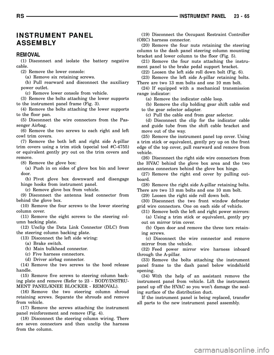
INSTRUMENT PANEL
ASSEMBLY
REMOVAL
(1) Disconnect and isolate the battery negative
cable.
(2) Remove the lower console:
(a) Remove six retaining screws.
(b) Pull rearward and disconnect the auxiliary
power outlet.
(c) Remove lower console from vehicle.
(3) Remove the bolts attaching the lower supports
to the instrument panel frame (Fig. 3).
(4) Remove the bolts attaching the lower supports
to the floor pan.
(5) Disconnect the wire connectors from the Pas-
senger Airbag.
(6) Remove the two screws to each right and left
cowl trim covers.
(7) Remove the both left and right side A-pillar
trim covers using a trim stick (special tool #C-4755)
or equivalent gently pry out on the trim covers and
remove.
(8) Remove the glove box:
(a) Push in on sides of glove box bin and lower
door.
(b) Pivot glove box downward and disengage
hinge hooks from instrument panel.
(c) Remove glove box from vehicle.
(9) Disconnect the antenna lead connector from
behind the glove box.
(10) Remove the four screws to the lower steering
column cover.
(11) Remove the eight screws to the steering col-
umn backing plate.
(12) Unclip the Data Link Connector (DLC) from
the steering column backing plate.
(13) Disconnect the left side wiring:
(a) Brake switch.
(b) Main bulkhead connector.
(c) Five harness connectors.
(d) Driver airbag connector.
(14) Remove the two screws to the hood release
handle.
(15) Remove five screws to steering column back-
ing plate and remove (Refer to 23 - BODY/INSTRU-
MENT PANEL/KNEE BLOCKER - REMOVAL).
(16) Remove the two steering column shroud
retaining screws. Separate the shrouds and remove
from vehicle.
(17) Remove the screws attaching the instrument
panel reinforcement and remove (Fig. 4).
(18) Disconnect the steering column wiring. There
are seven connectors and then unclip the harness
from the column.(19) Disconnect the Occupant Restraint Controller
(ORC) harness connector.
(20) Remove the four nuts retaining the steering
column to the dash panel steering column mounting
bracket and lower column to the floor (Fig. 5).
(21) Remove the four nuts attaching the instru-
ment panel to the brake pedal support bracket.
(22) Loosen the left side roll down bolt (Fig. 6).
(23) Remove the left side A-pillar retaining bolts.
There are two 13 mm bolts and one 10 mm bolt.
(24) If equipped with a mechanical transmission
range indicator:
(a) Remove the indicator cable loop.
(b) Remove the clip holding gear shift cable end
to the gear selector adapter.
(c) Pull the cable end from gear selector.
(d) Disconnect the clip for the indicator cable
and guide tube from the shift cable bracket and
move out of the way.
(25) Remove the instrument panel top cover. Using
a trim stick or equivalent, gently pry up on the front
edge of the top cover, pull rearward and remove from
vehicle.
(26) Disconnect the right side wire connectors from
the HVAC behind the glove box area and the two
antenna connectors behind the glove box hinge.
(27) Remove the right end cover by pulling out-
board.
(28) Remove the right side A-pillar retaining bolts.
There are two 13 mm bolts and one 10 mm bolt.
(29) Loosen the right side roll down bolt.
(30) Disconnect the two front window defroster
grid wire connectors. One on each side of vehicle.
(31) Remove both the left and right power mirrors:
(a) Using a trim stick or equivalent, gently pry
out on mirror trim cover.
(b) Open door and remove the three torx retain-
ing screws.
(c) Disconnect the wire connector and remove
mirror from the vehicle.
(32) Feed power mirror wire harness inboard
through the A-pillar.
(33) Remove the bolts attaching the instrument
panel frame to the dash panel below windshield
opening.
(34) With the help of an assistant remove the
instrument panel from vehicle. Lift the instrument
panel up off the HVAC so you won't damage the seal-
ing surface of the distribution duct.
If the instrument panel is being replaced, transfer
all parts to the new instrument panel assembly.
RSINSTRUMENT PANEL23-65
Page 2178 of 2585
(14) Install the four nuts retaining the steering
column and lower to the floor (Fig. 5).
(15) Connect the Occupant Restraint Controller
(ORC) harness connector.
(16) Connect the steering column wiring. There
are seven connectors and then clip the harness to the
column.
(17) Install the screws attaching the instrument
panel reinforcement (Fig. 4).
(18) Connect the shrouds and install the two steer-
ing column shroud retaining screws.
(19) Install five screws to the left under column
instrument panel reinforcement brace.
(20) Install the two screws to the hood release
handle.
(21) Connect the left side wiring:
(a) Brake switch.
(b) Main bulkhead connector.
(c) Five harness connectors.
(d) Driver airbag connector.
(22) Clip the Data Link Connector (DLC) to the
steering column backing plate.
(23) Install the eight screws to the steering column
backing plate.(24) Install the four screws to the lower steering
column cover.
(25) Install the glove box:
(a) Install glove box into the vehicle. Line up the
hinges and firmly snap together.
(b) Push in on sides of glove box bin and raise
door.
(26) Install the both left and right side A-pillar
trim covers. Position trim cover over slots and firmly
snap into place.
(27) Install the two screws to each right and left
cowl trim covers.
(28) Connect the wire connectors to the Passenger
Airbag.
(29) Install the bolts attaching the lower supports
to the floor pan.
(30) Install the bolts attaching the lower supports
to the instrument panel frame (Fig. 3).
(31) Install the lower console:
(a) Install lower console to vehicle.
(b) Connect the auxiliary power outlet.
(c) Install the six retaining screws.
(32) Connect the battery negative cable.
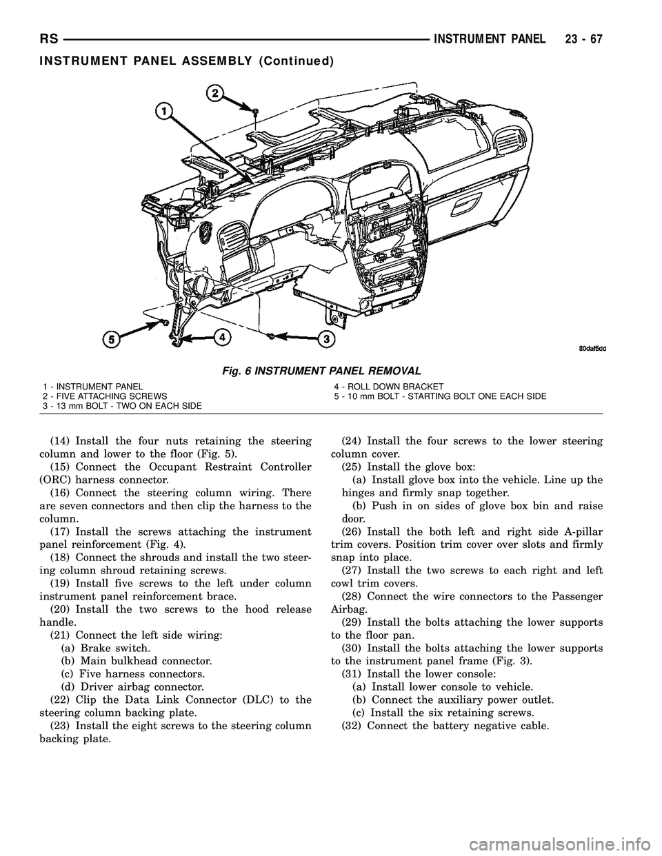
Fig. 6 INSTRUMENT PANEL REMOVAL
1 - INSTRUMENT PANEL
2 - FIVE ATTACHING SCREWS
3 - 13 mm BOLT - TWO ON EACH SIDE4 - ROLL DOWN BRACKET
5 - 10 mm BOLT - STARTING BOLT ONE EACH SIDE
RSINSTRUMENT PANEL23-67
INSTRUMENT PANEL ASSEMBLY (Continued)
Page 2180 of 2585
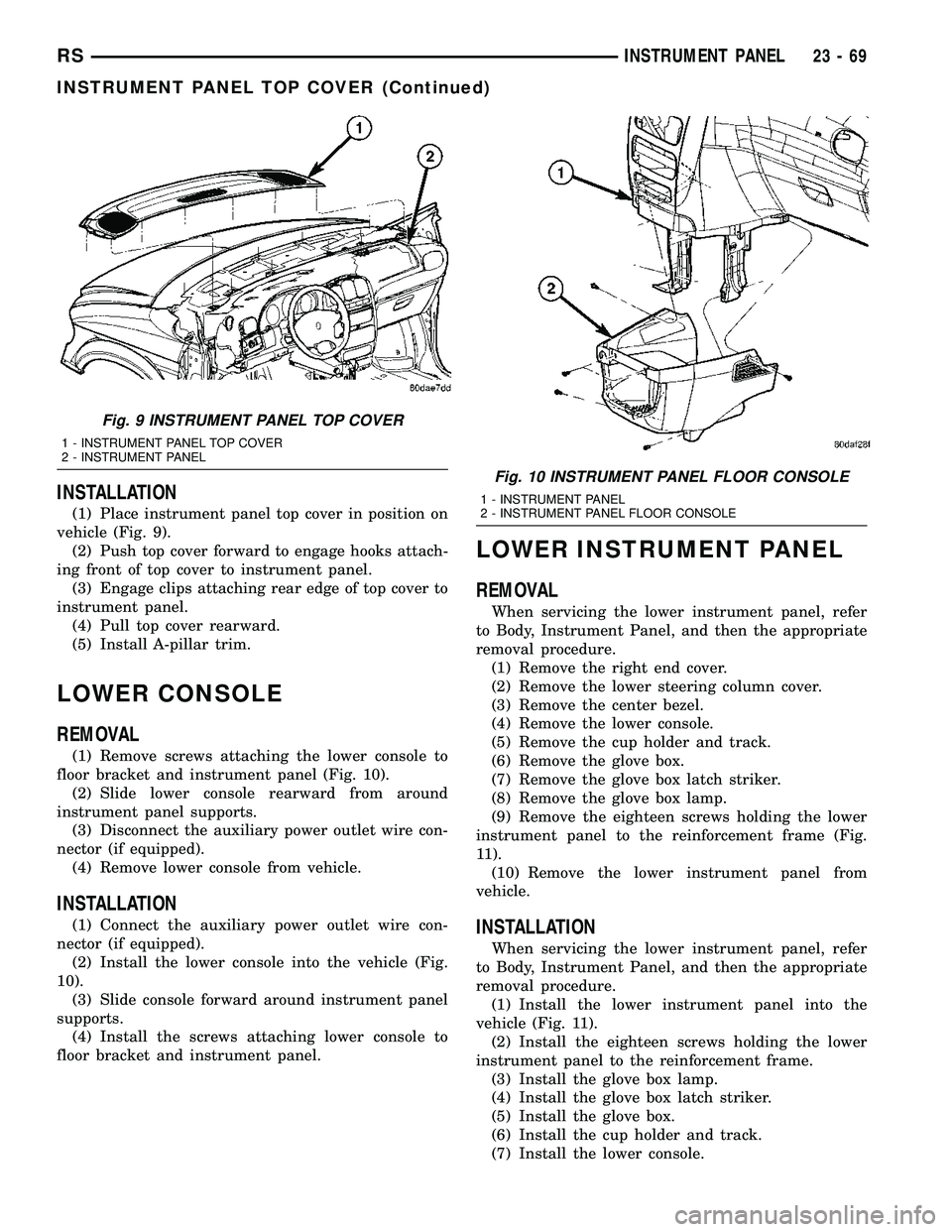
INSTALLATION
(1) Place instrument panel top cover in position on
vehicle (Fig. 9).
(2) Push top cover forward to engage hooks attach-
ing front of top cover to instrument panel.
(3) Engage clips attaching rear edge of top cover to
instrument panel.
(4) Pull top cover rearward.
(5) Install A-pillar trim.
LOWER CONSOLE
REMOVAL
(1) Remove screws attaching the lower console to
floor bracket and instrument panel (Fig. 10).
(2) Slide lower console rearward from around
instrument panel supports.
(3) Disconnect the auxiliary power outlet wire con-
nector (if equipped).
(4) Remove lower console from vehicle.
INSTALLATION
(1) Connect the auxiliary power outlet wire con-
nector (if equipped).
(2) Install the lower console into the vehicle (Fig.
10).
(3) Slide console forward around instrument panel
supports.
(4) Install the screws attaching lower console to
floor bracket and instrument panel.
LOWER INSTRUMENT PANEL
REMOVAL
When servicing the lower instrument panel, refer
to Body, Instrument Panel, and then the appropriate
removal procedure.
(1) Remove the right end cover.
(2) Remove the lower steering column cover.
(3) Remove the center bezel.
(4) Remove the lower console.
(5) Remove the cup holder and track.
(6) Remove the glove box.
(7) Remove the glove box latch striker.
(8) Remove the glove box lamp.
(9) Remove the eighteen screws holding the lower
instrument panel to the reinforcement frame (Fig.
11).
(10) Remove the lower instrument panel from
vehicle.
INSTALLATION
When servicing the lower instrument panel, refer
to Body, Instrument Panel, and then the appropriate
removal procedure.
(1) Install the lower instrument panel into the
vehicle (Fig. 11).
(2) Install the eighteen screws holding the lower
instrument panel to the reinforcement frame.
(3) Install the glove box lamp.
(4) Install the glove box latch striker.
(5) Install the glove box.
(6) Install the cup holder and track.
(7) Install the lower console.
Fig. 9 INSTRUMENT PANEL TOP COVER
1 - INSTRUMENT PANEL TOP COVER
2 - INSTRUMENT PANEL
Fig. 10 INSTRUMENT PANEL FLOOR CONSOLE
1 - INSTRUMENT PANEL
2 - INSTRUMENT PANEL FLOOR CONSOLE
RSINSTRUMENT PANEL23-69
INSTRUMENT PANEL TOP COVER (Continued)
Page 2191 of 2585

(16) Install first row seat.
(17) Connect the battery negative cable.
LEFT QUARTER TRIM PANEL
REMOVAL
CAUTION: Disconnect the negative cable clamp
from battery post. Damage to accessory feed circuit
can result.
(1) Remove first row seat.
(2) Remove second row seat, if equipped.
(3) Remove front door sill plate on three door vehi-
cle.
(4) Remove sliding door sill plate on four door
vehicle.
(5) Remove left quarter trim bolster.
(6) Remove C-pillar trim panel.
(7) Remove left D-pillar trim panel.
(8) Remove first row seat belt anchor.
(9) Remove second row seat belt anchor on long
wheel base vehicle.
(10) Remove screws attaching quarter trim to
quarter panel from bolster area.
(11) Remove screws attaching rear edge of quarter
trim to attaching bracket or inner quarter trim
panel.
(12) Disconnect wire connector from accessory
power outlet, if equipped.
(13) Remove quarter trim from quarter panel.
(14) Pass front seat belt and turning loop through
slot in quarter trim panel on three door vehicle.
(15) Pass first row seat belt through slot in quar-
ter trim panel.
(16) Pass second row seat belt, if equipped,
through slot in quarter trim panel on long wheel
base vehicle.
(17) Remove quarter trim panel from vehicle.
INSTALLATION
(1) Position quarter trim panel on vehicle.
(2) Pass second row seat belt, if equipped, through
slot in quarter trim panel on long wheel base vehicle.
(3) Pass first row seat belt through slot in quarter
trim panel.
(4) Connect wire connector into accessory power
outlet, if equipped.
(5) Align locating pins on backside of trim panel to
mating holes in inner panels.
(6) Position quarter trim panel on inner quarter
panel.
(7) Install screws attaching rear edge of quarter
trim to attaching bracket or inner quarter panel.
(8) Install screws attaching quarter trim to inner
quarter panel in bolster area.(9) Install second row seat belts anchor on long
wheel base vehicle. Tighten all seat belt bolts to 39
N´m (28 in. lbs.) torque.
(10) Install first row seat belt anchor.
(11) Install left D-pillar trim panel.
(12) Install C-pillar trim panel.
(13) Install upper left B-pillar trim on three door
vehicle.
(14) Install left quarter trim bolster.
(15) Install front door sill plate on three door vehi-
cle.
(16) Install sliding door sill plate on four door
vehicle.
(17) Install second row seat, if equipped.
(18) Install first row seat.
(19) Connect the battery negative cable.
REAR HEADER TRIM
REMOVAL
(1) Disengage hidden clips holding trim to rear
header (Fig. 11).
(2) Separate rear header trim from vehicle.
INSTALLATION
(1) Place rear header trim in position on vehicle.
(2) Align guide pins on trim to holes in header.
(3) Engage hidden clips to hold trim to rear
header.
(4) Engage interlock tabs at D-pillar trim.
Fig. 11 REAR HEADER TRIM
1 - REAR HEADER
2 - GUIDE PINS
3 - CLIPS
23 - 80 INTERIORRS
RIGHT QUARTER TRIM PANEL (Continued)
Page 2396 of 2585
HEATING & AIR CONDITIONING
TABLE OF CONTENTS
page page
HEATING & AIR CONDITIONING
DESCRIPTION
DESCRIPTION - ENGINE COOLING
SYSTEM REQUIREMENTS...............1
DESCRIPTION - HEATER AND AIR
CONDITIONER........................1
DESCRIPTION - SINGLE ZONE...........2
DESCRIPTION - DUAL ZONE.............2
DESCRIPTION - MANUAL THREE ZONE.....2
DESCRIPTION - AUTOMATIC THREE ZONE . . 3
OPERATION
OPERATION - HEATER AND AIR
CONDITIONER........................4
OPERATION - SINGLE ZONE.............4
OPERATION - DUAL ZONE...............5
OPERATION - MANUAL THREE ZONE......5
OPERATION - THREE ZONE ATC..........5DIAGNOSIS AND TESTING
DIAGNOSIS AND TESTING - A/C COOL
DOWN TEST..........................6
DIAGNOSIS AND TESTING - A/C
PERFORMANCE TEST..................7
DIAGNOSIS AND TESTING - HEATER
PERFORMANCE TEST.................10
SPECIFICATIONS
A/C SYSTEM.........................11
CONTROLS - FRONT.....................14
CONTROLS - REAR......................34
DISTRIBUTION - FRONT...................43
DISTRIBUTION - REAR....................56
PLUMBING - FRONT.....................64
PLUMBING - REAR......................97
CABIN HEATER........................112
HEATING & AIR
CONDITIONING
DESCRIPTION
DESCRIPTION - ENGINE COOLING SYSTEM
REQUIREMENTS
To maintain the performance level of the heating,
ventilation and air conditioning (HVAC) system, the
engine cooling system must be properly maintained.
The use of a bug screen is not recommended. Any
obstructions in front of the radiator or condenser will
reduce the performance of the air conditioning and
engine cooling systems.
The engine cooling system includes the radiator,
thermostat, radiator hoses and the engine coolant
pump. Refer to Cooling for more information before
opening or attempting any service to the engine cool-
ing system.
DESCRIPTION - HEATER AND AIR
CONDITIONER
A manually controlled single zone type heating-air
conditioning system, manually controlled dual zone
type heating-air conditioning system, manually con-
trolled three zone type heating-air conditioning sys-
tem or an automatic controlled three zone typeheating-air conditioning system is available on this
model.
All vehicles are equipped with a common heater,
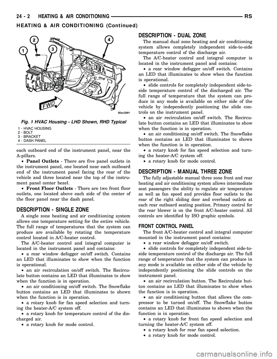
ventilation and air conditioning (HVAC) housing (Fig.
1). The system combines air conditioning, heating,
and ventilating capabilities in a single unit housing
mounted within the passenger compartment under
the instrument panel. The HVAC housing includes:
²Blower motor
²Blower motor resistor block or power module
(depending on application)
²Heater core
²Evaporator coil
²Blend door and actuator
²Mode door and actuator
²Recirculation door and actuator
Based upon the system and mode selected, condi-
tioned air can exit the HVAC housing through one or
a combination of the three main housing outlets:
defrost, panel or floor. The defrost and panel outlets
are located on the top of the housing and the floor
outlet is located on the bottom of the housing. Once
the conditioned air exits the unit housing, it is fur-
ther directed through molded plastic ducts to the var-
ious outlets in the vehicle interior. These outlets and
their locations are as follows:
²Defroster Outlet- A single large defroster out-
let is located in the center of the instrument panel
top cover, near the base of the windshield.
²Side Window Demister Outlets- There are
two side window demister outlets, one is located at
RSHEATING & AIR CONDITIONING24-1
Page 2397 of 2585
each outboard end of the instrument panel, near the
A-pillars.
²Panel Outlets- There are five panel outlets in
the instrument panel, one located near each outboard
end of the instrument panel facing the rear of the
vehicle and three located near the top of the instru-
ment panel center bezel.
²Front Floor Outlets- There are two front floor
outlets, one located above each side of the center of
the floor panel near the dash panel.
DESCRIPTION - SINGLE ZONE
A single zone heating and air conditioning system
allows one temperature setting for the entire vehicle.
The full range of temperatures that the system can
produce are available by rotating the temperature
control located in A/C-heater control.
The A/C-heater control and integral computer is
located in the instrument panel and contains:
²a rear window defogger on/off switch. Contains
an LED that illuminates to show when the function
is operational.
²an air recirculation on/off switch. The Recircu-
late button contains an LED that illuminates to show
when the function is in operation.
²an air conditioning on/off switch. The Snowflake
button contains an LED that illuminates to shown
when the function is in operation.
²a rotary knob for fan speed selection and turn-
ing the heater-A/C system off.
²a rotary knob for temperature control of the dis-
charged air.
²a rotary knob for mode control.
DESCRIPTION - DUAL ZONE
The manual dual zone heating and air conditioning
system allows completely independent side-to-side
temperature control of the discharge air.
The A/C-heater control and integral computer is
located in the instrument panel and contains:
²a rear window defogger on/off switch. Contains
an LED that illuminates to show when the function
is operational.
²slide controls for completely independent side-to-
side temperature control of the discharged air. The
full range of temperature that the system can pro-
duce in any mode is available on either side of the
vehicle by independently positioning the slide con-
trols on the instrument panel.
²an air recirculation on/off switch. The Recircu-
late button contains an LED that illuminates to show
when the function is in operation.
²an air conditioning on/off switch. The Snowflake
button contains an LED that illuminates to shown
when the function is in operation.
²a rotary knob for fan speed selection and turn-
ing the heater-A/C system off.
²a rotary knob for mode control.
DESCRIPTION - MANUAL THREE ZONE
The fully adjustable manual three zone front and rear
heating and air conditioning system allows intermediate
seat passengers the ability to regulate air temperature
as well as fan speed and provides floor outlets to the
rear of the right sliding door and overhead outlets at
each rear outboard seating position. Primary control for
the rear blower is on the front A/C-heater control. All
controls are identified by ISO graphic symbols.
FRONT CONTROL PANEL
The front A/C-heater control and integral computer
mounted in the instrument panel contains:
²a rear window defogger on/off switch.
²slide controls for completely independent side-to-
side temperature control of the discharge air. The full
range of temperature that the system can produce in
any mode is available on either side of the vehicle by
independently positioning the slide controls on the
instrument panel.
²an air recirculation button. The Recirculate but-
ton contains an LED that illuminates to show when
the function is in operation.
²an air conditioning button that allows the com-
pressor to be turned on/off. The Snowflake button
contains an LED that illuminates to shown when the
function is in operation.
²a rotary knob for front fan speed selection and
turning the heater-A/C system off.
²a rotary knob for rear fan speed selection.
²a rotary knob for mode control.
Fig. 1 HVAC Housing - LHD Shown, RHD Typical
1 - HVAC HOUSING
2 - BOLT
3 - BRACKET
4 - DASH PANEL
24 - 2 HEATING & AIR CONDITIONINGRS
HEATING & AIR CONDITIONING (Continued)