climate control CHRYSLER VOYAGER 2004 Service Manual
[x] Cancel search | Manufacturer: CHRYSLER, Model Year: 2004, Model line: VOYAGER, Model: CHRYSLER VOYAGER 2004Pages: 2585, PDF Size: 62.54 MB
Page 711 of 2585

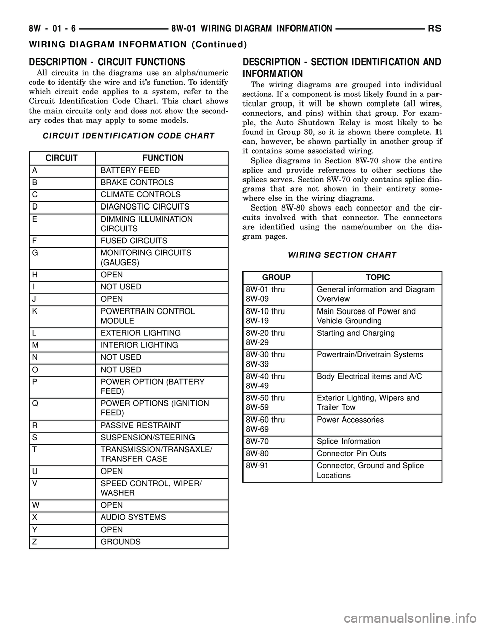
DESCRIPTION - CIRCUIT FUNCTIONS
All circuits in the diagrams use an alpha/numeric
code to identify the wire and it's function. To identify
which circuit code applies to a system, refer to the
Circuit Identification Code Chart. This chart shows
the main circuits only and does not show the second-
ary codes that may apply to some models.
CIRCUIT IDENTIFICATION CODE CHART
CIRCUIT FUNCTION
A BATTERY FEED
B BRAKE CONTROLS
C CLIMATE CONTROLS
D DIAGNOSTIC CIRCUITS
E DIMMING ILLUMINATION
CIRCUITS
F FUSED CIRCUITS
G MONITORING CIRCUITS
(GAUGES)
H OPEN
I NOT USED
J OPEN
K POWERTRAIN CONTROL
MODULE
L EXTERIOR LIGHTING
M INTERIOR LIGHTING
N NOT USED
O NOT USED
P POWER OPTION (BATTERY
FEED)
Q POWER OPTIONS (IGNITION
FEED)
R PASSIVE RESTRAINT
S SUSPENSION/STEERING
T TRANSMISSION/TRANSAXLE/
TRANSFER CASE
U OPEN
V SPEED CONTROL, WIPER/
WASHER
W OPEN
X AUDIO SYSTEMS
Y OPEN
Z GROUNDS
DESCRIPTION - SECTION IDENTIFICATION AND
INFORMATION
The wiring diagrams are grouped into individual
sections. If a component is most likely found in a par-
ticular group, it will be shown complete (all wires,
connectors, and pins) within that group. For exam-
ple, the Auto Shutdown Relay is most likely to be
found in Group 30, so it is shown there complete. It
can, however, be shown partially in another group if
it contains some associated wiring.
Splice diagrams in Section 8W-70 show the entire
splice and provide references to other sections the
splices serves. Section 8W-70 only contains splice dia-
grams that are not shown in their entirety some-
where else in the wiring diagrams.
Section 8W-80 shows each connector and the cir-
cuits involved with that connector. The connectors
are identified using the name/number on the dia-
gram pages.
WIRING SECTION CHART
GROUP TOPIC
8W-01 thru
8W-09General information and Diagram
Overview
8W-10 thru
8W-19Main Sources of Power and
Vehicle Grounding
8W-20 thru
8W-29Starting and Charging
8W-30 thru
8W-39Powertrain/Drivetrain Systems
8W-40 thru
8W-49Body Electrical items and A/C
8W-50 thru
8W-59Exterior Lighting, Wipers and
Trailer Tow
8W-60 thru
8W-69Power Accessories
8W-70 Splice Information
8W-80 Connector Pin Outs
8W-91 Connector, Ground and Splice
Locations
8W - 01 - 6 8W-01 WIRING DIAGRAM INFORMATIONRS
WIRING DIAGRAM INFORMATION (Continued)
Page 2415 of 2585

²The normally open terminal (87) provides a bat-
tery current output to the compressor clutch coil
through the compressor clutch relay output circuit
only when the compressor clutch relay coil is ener-
gized.
²The normally closed terminal (87A) is not con-
nected to any circuit in this application, but provides
a battery current output only when the compressor
clutch relay coil is de-energized.
The A/C compressor clutch relay cannot be
repaired and, if faulty or damaged, it must be
replaced. Refer to the appropriate wiring information
for diagnosis and testing of the micro-relay and for
complete HVAC wiring diagrams.
REMOVAL
(1) Disconnect and isolate the negative battery
cable.
(2) Remove the cover from the integrated power
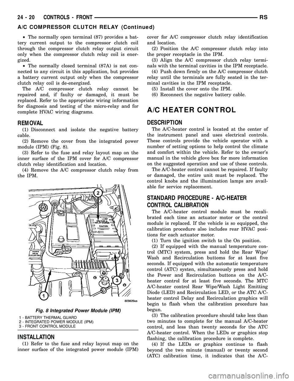
module (IPM) (Fig. 8).
(3) Refer to the fuse and relay layout map on the
inner surface of the IPM cover for A/C compressor
clutch relay identification and location.
(4) Remove the A/C compressor clutch relay from
the IPM.
INSTALLATION
(1) Refer to the fuse and relay layout map on the
inner surface of the integrated power module (IPM)cover for A/C compressor clutch relay identification
and location.
(2) Position the A/C compressor clutch relay into
the proper receptacle in the IPM.
(3) Align the A/C compressor clutch relay termi-
nals with the terminal cavities in the IPM receptacle.
(4) Push down firmly on the A/C compressor clutch
relay until the terminals are fully seated in the ter-
minal cavities in the IPM receptacle.
(5) Install the cover onto the IPM.
(6) Reconnect the negative battery cable.
A/C HEATER CONTROL
DESCRIPTION
The A/C-heater control is located at the center of
the instrument panel and uses electrical controls.
These controls provide the vehicle operator with a
number of setting options to help control the climate
and comfort within the vehicle. Refer to the owner's
manual in the vehicle glove box for more information
on the suggested operation and use of these controls.
The A/C-heater control cannot be repaired. If faulty
or damaged, the entire unit must be replaced. The
control knobs and the illumination lamps are avail-
able for service replacement.
STANDARD PROCEDURE - A/C-HEATER
CONTROL CALIBRATION
The A/C-heater control module must be recali-
brated each time an actuator motor or the control
module is replaced. If the vehicle is so equipped, the
calibration procedure also includes rear HVAC posi-
tions for each actuator motor.
(1) Turn the ignition switch to the On position.
(2) If equipped with the manual temperature con-
trol (MTC) system, press and hold the Rear Wipe/
Wash and Recirculation buttoms for at least five
seconds. If equipped with the automatic temperature
control (ATC) systen, simultaneously press and hold
the Power and Recirculation buttons on the A/C-
heater control for at least five seconds. The MTC
A/C-heater control Rear Wipe/Wash Light Emitting
Diode (LED) and Recirculation LED, or the ATC A/C-
heater control Delay and Recirculation graphics will
begin to flash when the calibration procedure has
begun.
(3) The calibration procedure should take less than
two minutes to complete for the manual A/C-heater
control, and less than twenty seconds for the ATC
A/C-heater control. When the LEDs or graphics stop
flashing, the calibration procedure is complete.
(4) If the LEDs or graphics continue to flash
beyond the two minute (manual) or twenty second
(ATC) calibration time, it indicates that the A/C-
Fig. 8 Integrated Power Module (IPM)
1 - BATTERY THERMAL GUARD
2 - INTEGRATED POWER MODULE (IPM)
3 - FRONT CONTROL MODULE
24 - 20 CONTROLS - FRONTRS
A/C COMPRESSOR CLUTCH RELAY (Continued)