engine oil capacity CHRYSLER VOYAGER 2004 Service Manual
[x] Cancel search | Manufacturer: CHRYSLER, Model Year: 2004, Model line: VOYAGER, Model: CHRYSLER VOYAGER 2004Pages: 2585, PDF Size: 62.54 MB
Page 364 of 2585
OPERATION
The cooling system is equipped with a pressure cap
that releases excessive pressure; maintaining a range
of 97-124 kPa (14-18 psi).
The cooling system will operate at higher than
atmospheric pressure. The higher pressure raises the
coolant boiling point thus, allowing increased radia-
tor cooling capacity.
There is also a vent valve in the center of the cap.
This valve also opens when coolant is cooling and
contracting, allowing the coolant to return to cooling
system from coolant reserve system tank by vacuum
through a connecting hose.If valve is stuck shut,
or the coolant recovery hose is pinched, the
radiator hoses will be collapsed on cool down.
Clean the vent valve (Fig. 17) and inspect cool-
ant recovery hose routing, to ensure proper
sealing when boiling point is reached.
The gasket in the cap seals the filler neck, so that
vacuum can be maintained, allowing coolant to be
drawn back into the radiator from the reserve tank.
If the gasket is dirty or damaged, a vacuum
may not be achieved, resulting is loss of coolant
and eventual overheating due to low coolant
level in radiator and engine.
DIAGNOSIS AND TESTING
DIAGNOSIS AND TESTING - COOLING SYSTEM
PRESSURE CAP TESTING
Dip the pressure cap in water. Clean any deposits
off the vent valve or its seat and apply cap to end of
the Pressure Cap Test Adaptor that is included with
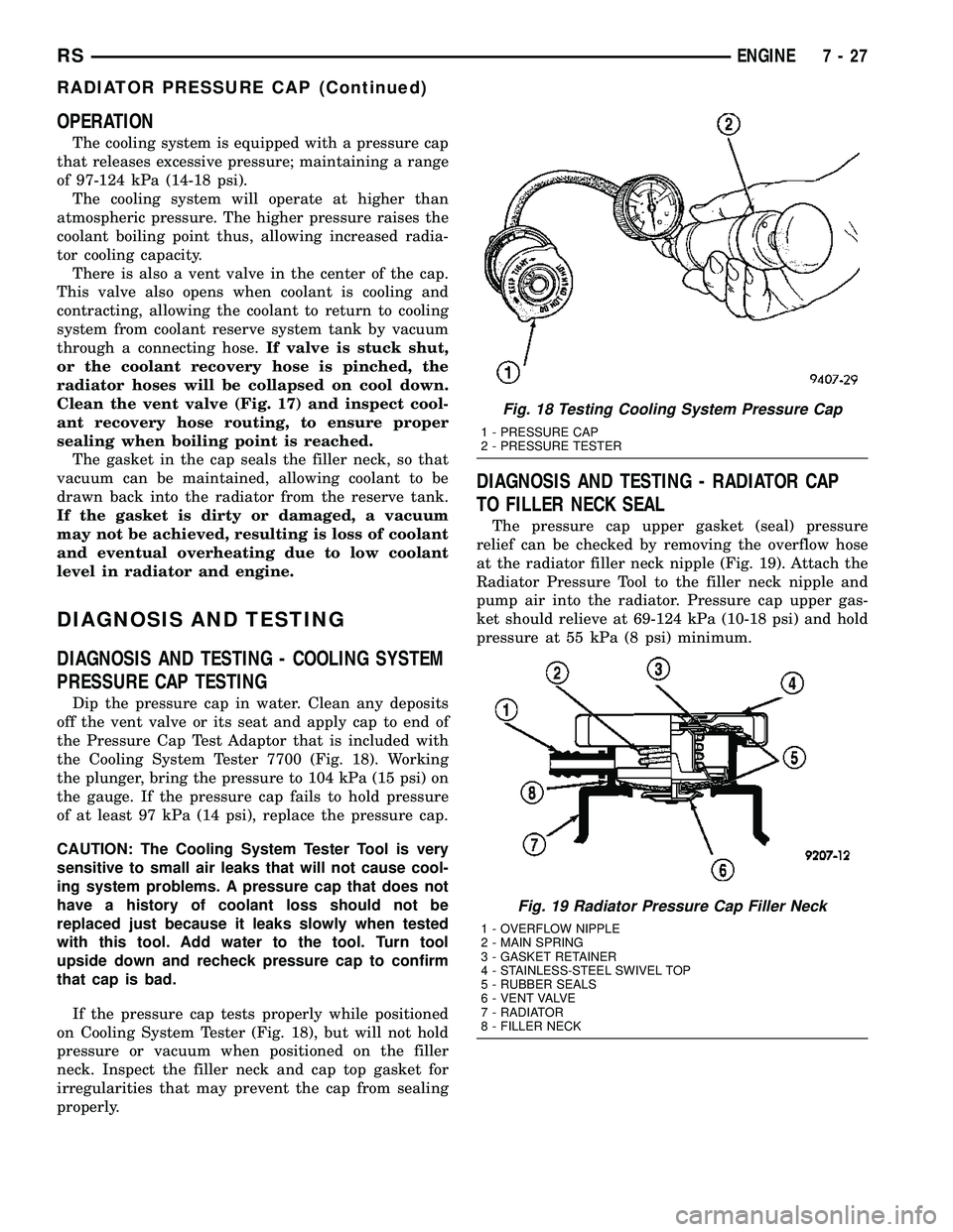
the Cooling System Tester 7700 (Fig. 18). Working
the plunger, bring the pressure to 104 kPa (15 psi) on
the gauge. If the pressure cap fails to hold pressure
of at least 97 kPa (14 psi), replace the pressure cap.
CAUTION: The Cooling System Tester Tool is very
sensitive to small air leaks that will not cause cool-
ing system problems. A pressure cap that does not
have a history of coolant loss should not be
replaced just because it leaks slowly when tested
with this tool. Add water to the tool. Turn tool
upside down and recheck pressure cap to confirm
that cap is bad.
If the pressure cap tests properly while positioned
on Cooling System Tester (Fig. 18), but will not hold
pressure or vacuum when positioned on the filler
neck. Inspect the filler neck and cap top gasket for
irregularities that may prevent the cap from sealing
properly.
DIAGNOSIS AND TESTING - RADIATOR CAP
TO FILLER NECK SEAL
The pressure cap upper gasket (seal) pressure
relief can be checked by removing the overflow hose
at the radiator filler neck nipple (Fig. 19). Attach the
Radiator Pressure Tool to the filler neck nipple and
pump air into the radiator. Pressure cap upper gas-
ket should relieve at 69-124 kPa (10-18 psi) and hold
pressure at 55 kPa (8 psi) minimum.
Fig. 18 Testing Cooling System Pressure Cap
1 - PRESSURE CAP
2 - PRESSURE TESTER
Fig. 19 Radiator Pressure Cap Filler Neck
1 - OVERFLOW NIPPLE
2 - MAIN SPRING
3 - GASKET RETAINER
4 - STAINLESS-STEEL SWIVEL TOP
5 - RUBBER SEALS
6 - VENT VALVE
7 - RADIATOR
8 - FILLER NECK
RSENGINE7-27
RADIATOR PRESSURE CAP (Continued)
Page 432 of 2585
SPIRAL-PLATE BATTERY CHARGE RATE TABLE
Voltage Minutes
14.4 volts maximum up to 10 minutes
13.0 to 14 volts up to 20 minutes
12.9 volts or less up to 30 minutes
CHARGING TIME REQUIRED
The time required to charge a battery will vary,
depending upon the following factors:
²Battery Capacity- A completely discharged
heavy-duty battery requires twice the charging time
of a small capacity battery.
²Temperature- A longer time will be needed to
charge a battery at -18É C (0É F) than at 27É C
(80É F). When a fast battery charger is connected to a
cold battery, the current accepted by the battery will
be very low at first. As the battery warms, it will
accept a higher charging current rate (amperage).
²Charger Capacity- A battery charger that
supplies only five amperes will require a longer
charging time. A battery charger that supplies eight
amperes will require a shorter charging time.
²State-Of-Charge- A completely discharged bat-
tery requires more charging time than a partially
discharged battery. Electrolyte is nearly pure water
in a completely discharged battery. At first, the
charging current (amperage) will be low. As the bat-
tery charges, the specific gravity of the electrolyte
will gradually rise.
The Battery Charging Time Table gives an indica-
tion of the time required to charge a typical battery
at room temperature based upon the battery state-of-
charge and the charger capacity.
SPIRAL-PLATE BATTERY CHARGING TIME
TABLE
Charging
Amperage5 Amps 8 Amps
Open Circuit
VoltageHours Charging @ 21É C
(70É F)
12.25 to 12.49 6 hours 3 hours
12.00 to 12.24 10 hours 5 hours
10.00 to 11.99 14 hours 7 hours
Below 10.00 18 hours 9 hours
STANDARD PROCEDURE - CONVENTIONAL
BATTERY CHARGING
Vehicles equipped with a diesel engine utilize a
unique spiral plate battery. This battery has a maxi-
mum charging voltage that must be used in order to
restore the battery to its full potential, failure to usethe spiral plate battery charging procedure could
result in damage to the battery or personal injury.
Battery charging is the means by which the bat-
tery can be restored to its full voltage potential. A
battery is fully-charged when:
²Micro 420 battery tester indicates battery is OK.
²Open-circuit voltage of the battery is 12.65 volts
or above.
²Battery passes Load Test multiple times.
WARNING: IF THE BATTERY SHOWS SIGNS OF
FREEZING, LEAKING, LOOSE POSTS, DO NOT
TEST, ASSIST-BOOST, OR CHARGE. THE BATTERY
MAY ARC INTERNALLY AND EXPLODE. PERSONAL
INJURY AND/OR VEHICLE DAMAGE MAY RESULT.
WARNING: EXPLOSIVE HYDROGEN GAS FORMS IN
AND AROUND THE BATTERY. DO NOT SMOKE,
USE FLAME, OR CREATE SPARKS NEAR THE BAT-
TERY. PERSONAL INJURY AND/OR VEHICLE DAM-
AGE MAY RESULT.
WARNING: THE BATTERY CONTAINS SULFURIC
ACID, WHICH IS POISONOUS AND CAUSTIC. AVOID
CONTACT WITH THE SKIN, EYES, OR CLOTHING.
IN THE EVENT OF CONTACT, FLUSH WITH WATER
AND CALL A PHYSICIAN IMMEDIATELY. KEEP OUT
OF THE REACH OF CHILDREN.
WARNING: IF THE BATTERY IS EQUIPPED WITH
REMOVABLE CELL CAPS, BE CERTAIN THAT EACH
OF THE CELL CAPS IS IN PLACE AND TIGHT
BEFORE THE BATTERY IS RETURNED TO SER-
VICE. PERSONAL INJURY AND/OR VEHICLE DAM-
AGE MAY RESULT FROM LOOSE OR MISSING
CELL CAPS.
CAUTION: Always disconnect and isolate the bat-
tery negative cable before charging a battery. Do
not exceed sixteen volts while charging a battery.
Damage to the vehicle electrical system compo-
nents may result.
CAUTION: Battery electrolyte will bubble inside the
battery case during normal battery charging. Elec-
trolyte boiling or being discharged from the battery
vents indicates a battery overcharging condition.
Immediately reduce the charging rate or turn off the
charger to evaluate the battery condition. Damage
to the battery may result from overcharging.
RSBATTERY SYSTEM8F-11
BATTERY (Continued)
Page 468 of 2585
SPIRAL-PLATE BATTERY CHARGE RATE TABLEVoltage Minutes
14.4 volts maximum up to 10 minutes 13.0 to 14 volts up to 20 minutes
12.9 volts or less up to 30 minutes
CHARGING TIME REQUIRED
The time required to charge a battery will vary,
depending upon the following factors: ² Battery Capacity - A completely discharged
heavy-duty battery requires twice the charging time
of a small capacity battery. ² Temperature - A longer time will be needed to
charge a battery at -18É C (0É F) than at 27É C (80É
F). When a fast battery charger is connected to a cold
battery, the current accepted by the battery will be
very low at first. As the battery warms, it will accept
a higher charging current rate (amperage). ² Charger Capacity - A battery charger that
supplies only five amperes will require a longer
charging time. A battery charger that supplies eight
amperes will require a shorter charging time. ² State-Of-Charge - A completely discharged bat-
tery requires more charging time than a partially
discharged battery. Electrolyte is nearly pure water
in a completely discharged battery. At first, the
charging current (amperage) will be low. As the bat-
tery charges, the specific gravity of the electrolyte
will gradually rise. The Battery Charging Time Table gives an indica-
tion of the time required to charge a typical battery
at room temperature based upon the battery state-of-
charge and the charger capacity.
SPIRAL-PLATE BATTERY CHARGING TIME TABLE
Charging
Amperage 5 Amps 8 Amps
Open Circuit Voltage Hours Charging @ 21É
C (70É F)
12.25 to 12.49 6 hours 3 hours
12.00 to 12.24 10 hours 5 hours 10.00 to 11.99 14 hours 7 hours Below 10.00 18 hours 9 hours
STANDARD PROCEDURE - CONVENTIONAL
BATTERY CHARGING
Vehicles equipped with a diesel engine utilize a
unique spiral plate battery. This battery has a maxi-
mum charging voltage that must be used in order to
restore the battery to its full potential, failure to use the spiral plate battery charging procedure could
result in damage to the battery or personal injury.
Battery charging is the means by which the bat-
tery can be restored to its full voltage potential. A
battery is fully-charged when: ² Micro 420 battery tester indicates battery is OK.
² Open-circuit voltage of the battery is 12.65 volts
or above. ² Battery passes Load Test multiple times.
WARNING: IF THE BATTERY SHOWS SIGNS OF
FREEZING, LEAKING, LOOSE POSTS, DO NOT
TEST, ASSIST-BOOST, OR CHARGE. THE BATTERY
MAY ARC INTERNALLY AND EXPLODE. PERSONAL
INJURY AND/OR VEHICLE DAMAGE MAY RESULT.
WARNING: EXPLOSIVE HYDROGEN GAS FORMS IN
AND AROUND THE BATTERY. DO NOT SMOKE,
USE FLAME, OR CREATE SPARKS NEAR THE BAT-
TERY. PERSONAL INJURY AND/OR VEHICLE DAM-
AGE MAY RESULT.
WARNING: THE BATTERY CONTAINS SULFURIC
ACID, WHICH IS POISONOUS AND CAUSTIC. AVOID
CONTACT WITH THE SKIN, EYES, OR CLOTHING.
IN THE EVENT OF CONTACT, FLUSH WITH WATER
AND CALL A PHYSICIAN IMMEDIATELY. KEEP OUT
OF THE REACH OF CHILDREN.
WARNING: IF THE BATTERY IS EQUIPPED WITH
REMOVABLE CELL CAPS, BE CERTAIN THAT EACH
OF THE CELL CAPS IS IN PLACE AND TIGHT
BEFORE THE BATTERY IS RETURNED TO SER-
VICE. PERSONAL INJURY AND/OR VEHICLE DAM-
AGE MAY RESULT FROM LOOSE OR MISSING
CELL CAPS.
CAUTION: Always disconnect and isolate the bat-
tery negative cable before charging a battery. Do
not exceed sixteen volts while charging a battery.
Damage to the vehicle electrical system compo-
nents may result.
CAUTION: Battery electrolyte will bubble inside the
battery case during normal battery charging. Elec-
trolyte boiling or being discharged from the battery
vents indicates a battery overcharging condition.
Immediately reduce the charging rate or turn off the
charger to evaluate the battery condition. Damage
to the battery may result from overcharging.
RS BATTERY SYSTEM8Fs-11
BATTERY (Continued)
Page 2402 of 2585
required. If the test is failed, the snowflake icon and
the DELAY text will continue to blink across ignition
cycles until the vehicle has been driven for greater
than 1.6 km (8 miles).
DIAGNOSIS AND TESTING - A/C
PERFORMANCE TEST
The A/C system is designed to remove heat and
humidity from the air entering the passenger com-
partment. The evaporator, located in the HVAC hous-
ing, is cooled to temperatures near the freezing point.
As warm damp air passes over the fins in the A/C
evaporator, moisture in the air condenses to water,
dehumidifying the air. Condensation on the evapora-
tor fins reduces the evaporators ability to absorb
heat. During periods of high heat and humidity, an
A/C system will be less effective. With the instru-
ment control set to recirculation mode, only air from
the passenger compartment passes through the A/C
evaporator. As the passenger compartment air dehu-
midifies, A/C performance levels rise.
Humidity has an important bearing on the temper-
ature of the air delivered to the interior of the vehi-
cle. It is important to understand the effect that
humidity has on the performance of the A/C system.
When humidity is high, the A/C evaporator has to
perform a double duty. It must lower the air temper-
ature, and it must lower the temperature of the
moisture in the air that condenses on the evaporator
fins. Condensing the moisture in the air transfers
heat energy into the evaporator fins and tubing. This
reduces the amount of heat the A/C evaporator can
absorb from the air. High humidity greatly reduces
the ability of the A/C evaporator to lower the temper-
ature of the air.
However, evaporator capacity used to reduce the
amount of moisture in the air is not wasted. Wring-
ing some of the moisture out of the air entering the
vehicle adds to the comfort of the passengers.
Although, an owner may expect too much from their
A/C system on humid days. A performance test is the
best way to determine whether the system is per-
forming up to design standards. This test also pro-
vides valuable clues as to the possible cause of
trouble with the A/C system. The ambient air tem-perature in the location where the vehicle will be
tested must be a minimum of 21É C (70É F) for this
test.
PERFORMANCE TEST PROCEDURE
WARNING: REFER TO THE APPLICABLE WARN-
INGS AND CAUTIONS FOR THIS SYSTEM BEFORE
PERFORMING THE FOLLOWING OPERATION (Refer
to 24 - HEATING & AIR CONDITIONING/PLUMBING -
FRONT - WARNING - A/C PLUMBING) and (Refer to
24 - HEATING & AIR CONDITIONING/PLUMBING -
FRONT - CAUTION - A/C PLUMBING).
NOTE: When connecting the service equipment
coupling to the line fitting, verify that the valve of
the coupling is fully closed. This will reduce the
amount of effort required to make the connection.
(1) Connect a tachometer and a manifold gauge
set.
(2) Set the mode control to the Recirculation Mode
position, the temperature control to the full cool posi-
tion and the blower to the highest speed position.
(3) Start the engine and hold at 1,000 rpm with
the A/C compressor clutch engaged.
(4) The engine should be warmed up to operating
temperature with the doors closed and windows
open.
(5) Insert a thermometer in the driver's side center
panel A/C-heater outlet and operate the engine for
five minutes.
(6) If the compressor clutch does not engage, pro-
ceed with diagnosis of the compressor clutch coil.
(Refer to 24 - HEATING & AIR CONDITIONING/
CONTROLS - FRONT/COMPRESSOR CLUTCH
COIL - DIAGNOSIS AND TESTING).
(7) With the A/C compressor clutch engaged, com-
pare the air temperature at the center panel outlet
and the compressor discharge pressure to the A/C
Performance Temperature and Pressure chart. The
compressor clutch may cycle, depending upon the
ambient temperature and humidity. If the clutch
cycles, use the readings obtained before the clutch
disengaged.
RSHEATING & AIR CONDITIONING24-7
HEATING & AIR CONDITIONING (Continued)
Page 2406 of 2585
MECHANICAL PROBLEMS
Possible causes of insufficient heat due to mechan-
ical problems are as follows:
²Obstructed cowl air intake.
²Obstructed heater system outlets.
²Blend door not functioning properly.
TEMPERATURE CONTROL
If the heater outlet air temperature cannot be
adjusted with the temperature control knob on the
A/C-heater control panel, the following could require
service:
²Blend door binding.²Faulty blend door actuator.
²Faulty A/C-heater control.
²Faulty related wiring harness or connectors.
²Improper engine coolant temperature.
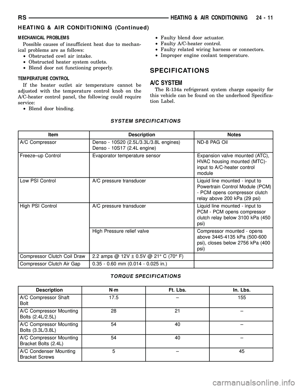
SPECIFICATIONS
A/C SYSTEM
The R-134a refrigerant system charge capacity for
this vehicle can be found on the underhood Specifica-
tion Label.
SYSTEM SPECIFICATIONS
Item Description Notes
A/C Compressor Denso - 10S20 (2.5L/3.3L/3.8L engines)
Denso - 10S17 (2.4L engine)ND-8 PAG Oil
Freeze±up Control Evaporator temperature sensor Expansion valve mounted (ATC),
HVAC housing mounted (MTC)-
input to A/C-heater control
module
Low PSI Control A/C pressure transducer Liquid line mounted - input to
Powertrain Control Module (PCM)
- PCM opens compressor clutch
relay above 200 kPa (29 psi)
High PSI Control A/C pressure transducer Liquid line mounted - input to
PCM - PCM opens compressor
clutch relay below 3100 kPa (450
psi)
High Pressure relief valve Compressor mounted - opens
above 3445-4135 kPa (500-600
psi), closes below 2756 kPa (400
psi)
Compressor Clutch Coil Draw 2.2 amps @ 12V 0.5V @ 21É C (70É F)
Compressor Clutch Air Gap 0.35 - 0.60 mm (0.014 - 0.025 in.)
TORQUE SPECIFICATIONS
Description N´m Ft. Lbs. In. Lbs.
A/C Compressor Shaft
Bolt17.5 ± 155
A/C Compressor Mounting
Bolts (2.4L/2.5L)28 21 ±
A/C Compressor Mounting
Bolts (3.3L/3.8L)54 40 ±
A/C Compressor Mounting
Bracket Bolts (2.4L)54 40 ±
A/C Condenser Mounting
Bracket Screws5±45
RSHEATING & AIR CONDITIONING24-11
HEATING & AIR CONDITIONING (Continued)
Page 2414 of 2585
COOLING/ACCESSORY DRIVE/DRIVE BELTS -
3.3L/3.8L - INSTALLATION).
(15) Lower the vehicle.
(16) Reconnect the battery negative cable.
CLUTCH BREAK-IN
After a new compressor clutch has been installed,
cycle the compressor clutch approximately twenty
times (five seconds on, then five seconds off). During
this procedure, set the A/C-heater control to the A/C
Recirculation Mode, the blower motor switch in the
highest speed position, and the engine speed at 1500
to 2000 rpm. This procedure (burnishing) will seat
the opposing friction surfaces and provide a higher
compressor clutch torque capability.
A/C COMPRESSOR CLUTCH
RELAY
DESCRIPTION
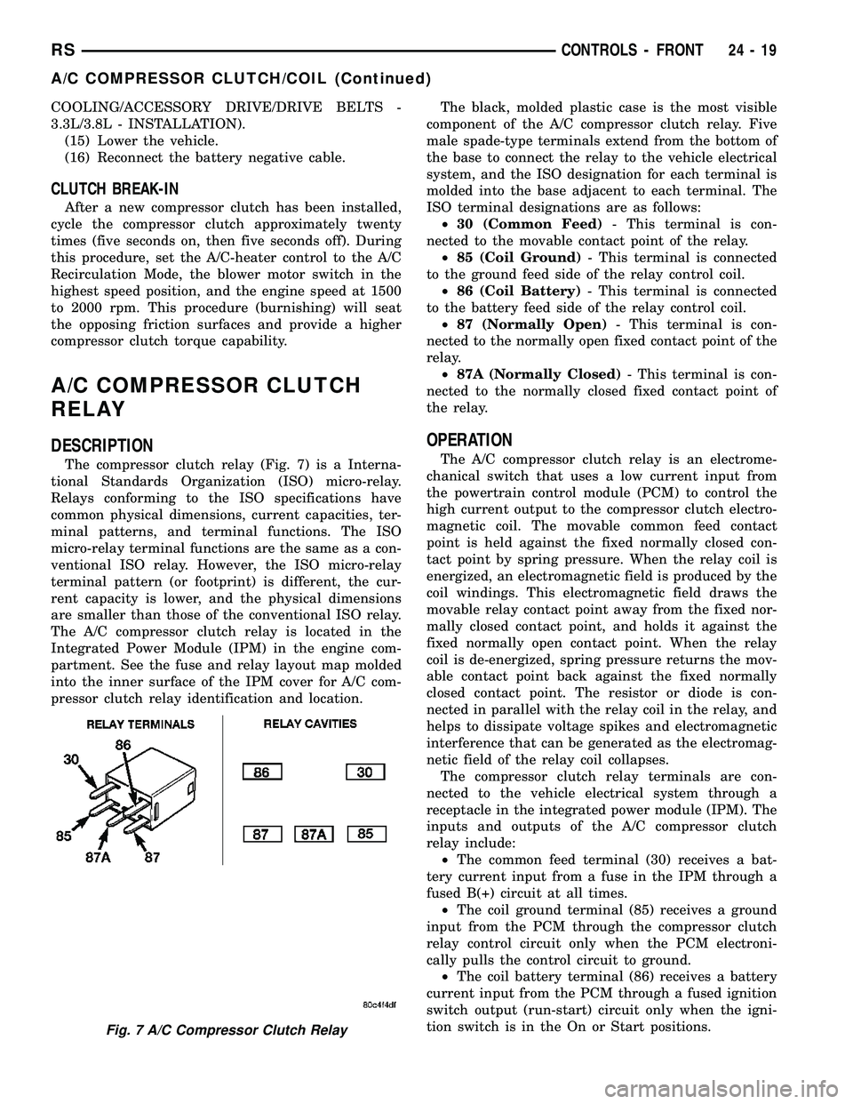
The compressor clutch relay (Fig. 7) is a Interna-
tional Standards Organization (ISO) micro-relay.
Relays conforming to the ISO specifications have
common physical dimensions, current capacities, ter-
minal patterns, and terminal functions. The ISO
micro-relay terminal functions are the same as a con-
ventional ISO relay. However, the ISO micro-relay
terminal pattern (or footprint) is different, the cur-
rent capacity is lower, and the physical dimensions
are smaller than those of the conventional ISO relay.
The A/C compressor clutch relay is located in the
Integrated Power Module (IPM) in the engine com-
partment. See the fuse and relay layout map molded
into the inner surface of the IPM cover for A/C com-
pressor clutch relay identification and location.The black, molded plastic case is the most visible
component of the A/C compressor clutch relay. Five
male spade-type terminals extend from the bottom of
the base to connect the relay to the vehicle electrical
system, and the ISO designation for each terminal is
molded into the base adjacent to each terminal. The
ISO terminal designations are as follows:
²30 (Common Feed)- This terminal is con-
nected to the movable contact point of the relay.
²85 (Coil Ground)- This terminal is connected
to the ground feed side of the relay control coil.
²86 (Coil Battery)- This terminal is connected
to the battery feed side of the relay control coil.
²87 (Normally Open)- This terminal is con-
nected to the normally open fixed contact point of the
relay.
²87A (Normally Closed)- This terminal is con-
nected to the normally closed fixed contact point of
the relay.
OPERATION
The A/C compressor clutch relay is an electrome-
chanical switch that uses a low current input from
the powertrain control module (PCM) to control the
high current output to the compressor clutch electro-
magnetic coil. The movable common feed contact
point is held against the fixed normally closed con-
tact point by spring pressure. When the relay coil is
energized, an electromagnetic field is produced by the
coil windings. This electromagnetic field draws the
movable relay contact point away from the fixed nor-
mally closed contact point, and holds it against the
fixed normally open contact point. When the relay
coil is de-energized, spring pressure returns the mov-
able contact point back against the fixed normally
closed contact point. The resistor or diode is con-
nected in parallel with the relay coil in the relay, and
helps to dissipate voltage spikes and electromagnetic
interference that can be generated as the electromag-
netic field of the relay coil collapses.
The compressor clutch relay terminals are con-
nected to the vehicle electrical system through a
receptacle in the integrated power module (IPM). The
inputs and outputs of the A/C compressor clutch
relay include:
²The common feed terminal (30) receives a bat-
tery current input from a fuse in the IPM through a
fused B(+) circuit at all times.
²The coil ground terminal (85) receives a ground
input from the PCM through the compressor clutch
relay control circuit only when the PCM electroni-
cally pulls the control circuit to ground.
²The coil battery terminal (86) receives a battery
current input from the PCM through a fused ignition
switch output (run-start) circuit only when the igni-
tion switch is in the On or Start positions.
Fig. 7 A/C Compressor Clutch Relay
RSCONTROLS - FRONT24-19
A/C COMPRESSOR CLUTCH/COIL (Continued)
Page 2419 of 2585
(3) Connect the HVAC wire harness connector to
the blend door actuator.
(4) Install the silencer under the driver side end of
the instrument panel (Refer to 23 - BODY/INSTRU-
MENT PANEL/INSTRUMENT PANEL SILENCER -
INSTALLATION).
(5) Reconnect the battery negative cable.
(6) Perform the heater-A/C control calibration pro-
cedure (Refer to 24 - HEATING & AIR CONDITION-
ING/CONTROLS - FRONT/A/C-HEATER CONTROL
- STANDARD PROCEDURE - HEATER-A/C CON-
TROL CALIBRATION).
BLOWER MOTOR RELAY
DESCRIPTION
The blower motor relay is a International Stan-
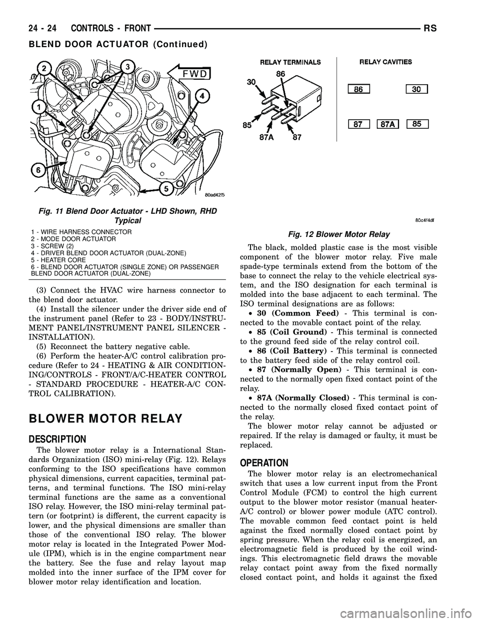
dards Organization (ISO) mini-relay (Fig. 12). Relays
conforming to the ISO specifications have common
physical dimensions, current capacities, terminal pat-
terns, and terminal functions. The ISO mini-relay
terminal functions are the same as a conventional
ISO relay. However, the ISO mini-relay terminal pat-
tern (or footprint) is different, the current capacity is
lower, and the physical dimensions are smaller than
those of the conventional ISO relay. The blower
motor relay is located in the Integrated Power Mod-
ule (IPM), which is in the engine compartment near
the battery. See the fuse and relay layout map
molded into the inner surface of the IPM cover for
blower motor relay identification and location.The black, molded plastic case is the most visible
component of the blower motor relay. Five male
spade-type terminals extend from the bottom of the
base to connect the relay to the vehicle electrical sys-
tem, and the ISO designation for each terminal is
molded into the base adjacent to each terminal. The
ISO terminal designations are as follows:
²30 (Common Feed)- This terminal is con-
nected to the movable contact point of the relay.
²85 (Coil Ground)- This terminal is connected
to the ground feed side of the relay control coil.
²86 (Coil Battery)- This terminal is connected
to the battery feed side of the relay control coil.
²87 (Normally Open)- This terminal is con-
nected to the normally open fixed contact point of the
relay.
²87A (Normally Closed)- This terminal is con-
nected to the normally closed fixed contact point of
the relay.
The blower motor relay cannot be adjusted or
repaired. If the relay is damaged or faulty, it must be
replaced.
OPERATION
The blower motor relay is an electromechanical
switch that uses a low current input from the Front
Control Module (FCM) to control the high current
output to the blower motor resistor (manual heater-
A/C control) or blower power module (ATC control).
The movable common feed contact point is held
against the fixed normally closed contact point by
spring pressure. When the relay coil is energized, an
electromagnetic field is produced by the coil wind-
ings. This electromagnetic field draws the movable
relay contact point away from the fixed normally
closed contact point, and holds it against the fixed
Fig. 11 Blend Door Actuator - LHD Shown, RHD
Typical
1 - WIRE HARNESS CONNECTOR
2 - MODE DOOR ACTUATOR
3 - SCREW (2)
4 - DRIVER BLEND DOOR ACTUATOR (DUAL-ZONE)
5 - HEATER CORE
6 - BLEND DOOR ACTUATOR (SINGLE ZONE) OR PASSENGER
BLEND DOOR ACTUATOR (DUAL-ZONE)Fig. 12 Blower Motor Relay
24 - 24 CONTROLS - FRONTRS
BLEND DOOR ACTUATOR (Continued)
Page 2432 of 2585
BLOWER MOTOR RELAY
DESCRIPTION
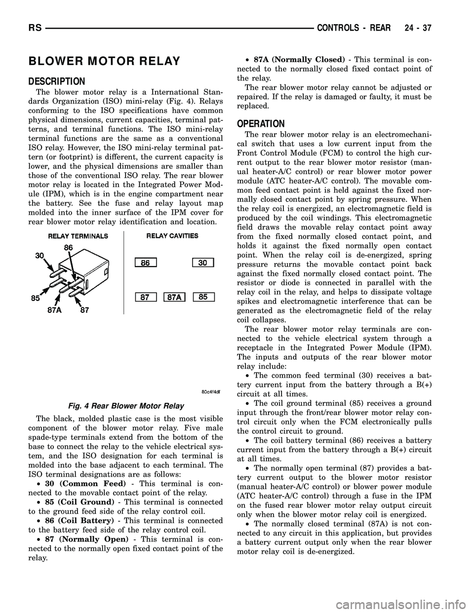
The blower motor relay is a International Stan-
dards Organization (ISO) mini-relay (Fig. 4). Relays
conforming to the ISO specifications have common
physical dimensions, current capacities, terminal pat-
terns, and terminal functions. The ISO mini-relay
terminal functions are the same as a conventional
ISO relay. However, the ISO mini-relay terminal pat-
tern (or footprint) is different, the current capacity is
lower, and the physical dimensions are smaller than
those of the conventional ISO relay. The rear blower
motor relay is located in the Integrated Power Mod-
ule (IPM), which is in the engine compartment near
the battery. See the fuse and relay layout map
molded into the inner surface of the IPM cover for
rear blower motor relay identification and location.
The black, molded plastic case is the most visible
component of the blower motor relay. Five male
spade-type terminals extend from the bottom of the
base to connect the relay to the vehicle electrical sys-
tem, and the ISO designation for each terminal is
molded into the base adjacent to each terminal. The
ISO terminal designations are as follows:
²30 (Common Feed)- This terminal is con-
nected to the movable contact point of the relay.
²85 (Coil Ground)- This terminal is connected
to the ground feed side of the relay control coil.
²86 (Coil Battery)- This terminal is connected
to the battery feed side of the relay control coil.
²87 (Normally Open)- This terminal is con-
nected to the normally open fixed contact point of the
relay.²87A (Normally Closed)- This terminal is con-
nected to the normally closed fixed contact point of
the relay.
The rear blower motor relay cannot be adjusted or
repaired. If the relay is damaged or faulty, it must be
replaced.
OPERATION
The rear blower motor relay is an electromechani-
cal switch that uses a low current input from the
Front Control Module (FCM) to control the high cur-
rent output to the rear blower motor resistor (man-
ual heater-A/C control) or rear blower motor power
module (ATC heater-A/C control). The movable com-
mon feed contact point is held against the fixed nor-
mally closed contact point by spring pressure. When
the relay coil is energized, an electromagnetic field is
produced by the coil windings. This electromagnetic
field draws the movable relay contact point away
from the fixed normally closed contact point, and
holds it against the fixed normally open contact
point. When the relay coil is de-energized, spring
pressure returns the movable contact point back
against the fixed normally closed contact point. The
resistor or diode is connected in parallel with the
relay coil in the relay, and helps to dissipate voltage
spikes and electromagnetic interference that can be
generated as the electromagnetic field of the relay
coil collapses.
The rear blower motor relay terminals are con-
nected to the vehicle electrical system through a
receptacle in the Integrated Power Module (IPM).
The inputs and outputs of the rear blower motor
relay include:
²The common feed terminal (30) receives a bat-
tery current input from the battery through a B(+)
circuit at all times.
²The coil ground terminal (85) receives a ground
input through the front/rear blower motor relay con-
trol circuit only when the FCM electronically pulls
the control circuit to ground.
²The coil battery terminal (86) receives a battery
current input from the battery through a B(+) circuit
at all times.
²The normally open terminal (87) provides a bat-
tery current output to the blower motor resistor
(manual heater-A/C control) or blower power module
(ATC heater-A/C control) through a fuse in the IPM
on the fused rear blower motor relay output circuit
only when the blower motor relay coil is energized.
²The normally closed terminal (87A) is not con-
nected to any circuit in this application, but provides
a battery current output only when the rear blower
motor relay coil is de-energized.
Fig. 4 Rear Blower Motor Relay
RSCONTROLS - REAR24-37
Page 2460 of 2585
SERVICE PORT VALVE CORE
DESCRIPTION.........................94
REMOVAL.............................94
INSTALLATION.........................94SUCTION LINE
REMOVAL.............................94
INSTALLATION.........................95
PLUMBING - FRONT
DESCRIPTION - REFRIGERANT LINE
The refrigerant lines and hoses are used to carry
the refrigerant between the various air conditioning
system components. A barrier hose design with a
nylon tube, which is sandwiched between rubber lay-
ers, is used for the R-134a air conditioning system on
this vehicle. This nylon tube helps to further contain
the R-134a refrigerant, which has a smaller molecu-
lar structure than R-12 refrigerant. The ends of the
refrigerant hoses are made from lightweight alumi-
num or steel, and commonly use braze-less fittings.
Any kinks or sharp bends in the refrigerant plumb-
ing will reduce the capacity of the entire air condi-
tioning system. Kinks and sharp bends reduce the
flow of refrigerant in the system. A good rule for the
flexible hose refrigerant lines is to keep the radius of
all bends at least ten times the diameter of the hose.
In addition, the flexible hose refrigerant lines should
be routed so they are at least 80 millimeters (3
inches) from an exhaust manifold.
OPERATION- REFRIGERANT LINES
High pressures are produced in the refrigerant sys-
tem when the air conditioning compressor is operat-
ing. Extreme care must be exercised to make sure
that each of the refrigerant system connections is
pressure-tight and leak free. It is a good practice to
inspect all flexible hose refrigerant lines at least once
a year to make sure they are in good condition and
properly routed.
The refrigerant lines and hoses are coupled with
other components of the HVAC system with either
O-rings or dual plane seals.
The refrigerant lines and hoses cannot be repaired
and, if faulty or damaged, they must be replaced.
WARNING
ENGINE COOLING SYSTEM
WARNING: THE ENGINE COOLING SYSTEM IS
DESIGNED TO DEVELOP INTERNAL PRESSURES
OF 97 TO 123 KILOPASCALS (14 TO 18 POUNDS
PER SQUARE INCH). DO NOT REMOVE OR
LOOSEN THE COOLANT PRESSURE CAP, CYLIN-
DER BLOCK DRAIN PLUGS, RADIATOR DRAIN,
RADIATOR HOSES, HEATER HOSES, OR HOSE
CLAMPS WHILE THE ENGINE COOLING SYSTEM ISHOT AND UNDER PRESSURE. FAILURE TO
OBSERVE THIS WARNING CAN RESULT IN SERI-
OUS BURNS FROM THE HEATED ENGINE COOL-
ANT. ALLOW THE VEHICLE TO COOL FOR A
MINIMUM OF 15 MINUTES BEFORE OPENING THE
COOLING SYSTEM FOR SERVICE.
A/C SYSTEM
WARNING: THE AIR CONDITIONING SYSTEM CON-
TAINS REFRIGERANT UNDER HIGH PRESSURE.
SEVERE PERSONAL INJURY MAY RESULT FROM
IMPROPER SERVICE PROCEDURES. REPAIRS
SHOULD ONLY BE PERFORMED BY QUALIFIED
SERVICE PERSONNEL.
AVOID BREATHING THE REFRIGERANT AND
REFRIGERANT OIL VAPOR OR MIST. EXPOSURE
MAY IRRITATE THE EYES, NOSE, AND/OR THROAT.
WEAR EYE PROTECTION WHEN SERVICING THE
AIR CONDITIONING REFRIGERANT SYSTEM. SERI-
OUS EYE INJURY CAN RESULT FROM DIRECT
CONTACT WITH THE REFRIGERANT. IF EYE CON-
TACT OCCURS, SEEK MEDICAL ATTENTION IMME-
DIATELY.
DO NOT EXPOSE THE REFRIGERANT TO OPEN
FLAME. POISONOUS GAS IS CREATED WHEN
REFRIGERANT IS BURNED. AN ELECTRONIC LEAK
DETECTOR IS RECOMMENDED.
IF ACCIDENTAL SYSTEM DISCHARGE OCCURS,
VENTILATE THE WORK AREA BEFORE RESUMING
SERVICE. LARGE AMOUNTS OF REFRIGERANT
RELEASED IN A CLOSED WORK AREA WILL DIS-
PLACE THE OXYGEN AND CAUSE SUFFOCATION.
THE EVAPORATION RATE OF R-134a REFRIGER-
ANT AT AVERAGE TEMPERATURE AND ALTITUDE
IS EXTREMELY HIGH. AS A RESULT, ANYTHING
THAT COMES IN CONTACT WITH THE REFRIGER-
ANT WILL FREEZE. ALWAYS PROTECT THE SKIN
OR DELICATE OBJECTS FROM DIRECT CONTACT
WITH THE REFRIGERANT.
THE R-134a SERVICE EQUIPMENT OR THE VEHI-
CLE REFRIGERANT SYSTEM SHOULD NOT BE
PRESSURE TESTED OR LEAK TESTED WITH COM-
PRESSED AIR. SOME MIXTURES OF AIR AND
R-134a HAVE BEEN SHOWN TO BE COMBUSTIBLE
AT ELEVATED PRESSURES. THESE MIXTURES ARE
POTENTIALLY DANGEROUS, AND MAY RESULT IN
FIRE OR EXPLOSION CAUSING INJURY OR PROP-
ERTY DAMAGE.
RSPLUMBING - FRONT24-65
Page 2465 of 2585
tion that meets SAE Standard J2210 to the refriger-
ant system.
(2) Attach a clamp-on thermocouple to the liquid
line. The thermocouple must be placed as close to the
A/C pressure transducer as possible to accurately
observe liquid line temperature.
(3) Bring the refrigerant system up to operating
temperature and pressure. This is done by allowing
the engine to run at idle under the following condi-
tions for five minutes.
(a) Front windows are open.
(b) Transaxle in Park.
(c) Front heater-A/C controls set to outside air,
full cool, panel mode, blower high, and compressor
engaged.
(d) If the vehicle is so equipped, the rear heater-
A/C controls must be set to full cool and blower
high.
(4) Raise the liquid line (discharge) pressure to
about 1793 kPa (260 psi) by placing a piece of card-
board over part of the front side of the condenser. To
place the cardboard properly, remove the upper radi-
ator sight shield from the front fascia. Cover only
enough of the condenser to raise and maintain the
liquid line pressure at the specified level.
(5) Observe the liquid line (discharge) pressure
and liquid line temperature. Using the Charge Deter-
mination Chart (Fig. 2), determine whether the
refrigerant system is operating within the Proper
Charge Range.
(a) If the refrigerant system is operating in the
Undercharged area of the chart, add 0.057 kilo-
gram (0.125 pound or 2 ounces) of refrigerant to
the system.
(b) If the refrigerant system is operating in the
Overcharged area of the chart, reclaim 0.057 kilo-
gram (0.125 pound or 2 ounces) of refrigerant from
the system.
(6) Recheck the system charge level following each
refrigerant adjustment. Continue this process until
the system readings are in the Proper Charge Range
area on the Charge Determination Chart (Fig. 2).
STANDARD PROCEDURE
STANDARD PROCEDURE - HANDLING TUBING
AND FITTINGS
CAUTION: The system must be completely empty
before opening any fitting or connection in the
refrigeration system. Open fittings with caution
even after the system has been emptied. If any
pressure is noticed as a fitting is loosened,
retighten fitting and evacuate the system again.
A good rule for the flexible hose lines is to keep theradius of all bends at least 10 times the diameter of
the hose. Sharper bends will reduce the flow of
refrigerant. The flexible hose lines should be routed
so they are at least 3 inches (80 mm) from the
exhaust manifold. Inspect all flexible hose lines to
make sure they are in good condition and properly
routed.
The use of correct wrenches when making connec-
tions is very important. Improper wrenches or
improper use of wrenches can damage the fittings.
The internal parts of the A/C system will remain sta-
ble as long as moisture-free refrigerant and refrig-
erant oil is used. Abnormal amounts of dirt,
moisture or air can upset the chemical stability.
This may cause operational troubles or even seri-
ous damage if present in more than very small
quantities. Before disconnecting a component,
clean the outside of the fittings thoroughly to pre-
vent contamination from entering the refrigerant
system.
When opening a refrigeration system, have every-
thing you will need to repair the system ready. This
will minimize the amount of time the system must
be opened. Cap or plug all lines and fittings as
soon as they are opened. This will help prevent the
entrance of dirt and moisture. All new lines and
components should be capped or sealed until they
are ready to be used. Before connecting a compo-
nent, clean the outside of the fittings thoroughly to
prevent contamination from entering the refrigerant
system.
All tools, including the refrigerant dispensing mani-
fold, the manifold gauge set, and test hoses should
be kept clean and dry.
Kinks in the refrigerant tubing or sharp bends in
the refrigerant hose lines will greatly reduce the
capacity of the entire system. High pressures are pro-
duced in the system when it is operating. Extreme
care must be exercised to make sure that all connec-
tions are pressure tight. Dirt and moisture can enter
the system when it is opened for repair or replace-
ment of lines or components. The refrigerant oil will
absorb moisture readily out of the air. This moisture
will convert into acids within a closed system.
STANDARD PROCEDURE - REFRIGERANT
SYSTEM SERVICE EQUIPMENT
WARNING: EYE PROTECTION MUST BE WORN
WHEN SERVICING AN AIR CONDITIONING REFRIG-
ERANT SYSTEM. TURN OFF (ROTATE CLOCKWISE)
ALL VALVES ON THE EQUIPMENT BEING USED
BEFORE CONNECTING TO, OR DISCONNECTING
FROM THE REFRIGERANT SYSTEM. FAILURE TO
OBSERVE THESE WARNINGS MAY RESULT IN PER-
SONAL INJURY.
24 - 70 PLUMBING - FRONTRS
PLUMBING - FRONT (Continued)