fuse box diagram CHRYSLER VOYAGER 2004 Service Manual
[x] Cancel search | Manufacturer: CHRYSLER, Model Year: 2004, Model line: VOYAGER, Model: CHRYSLER VOYAGER 2004Pages: 2585, PDF Size: 62.54 MB
Page 503 of 2585
Refer to the description of the heated seat switch
later in this section for additional information.
Hard wired circuitry connects the heated seat sys-
tem components to each other through the electrical
system of the vehicle. These hard wired circuits are
integral to several wire harnesses, which are routed
throughout the vehicle and retained by many differ-
ent methods. These circuits may be connected to each
other, to the vehicle electrical system and to the
heated seat system components through the use of a
combination of soldered splices and splice block con-
nectors. Refer to Wiring for complete system wiring
schematics. The wiring information also includes the
proper wire and connector repair procedures, further
details on wire harness routing and retention, as well
as pin-out and location views for the various wire
harness connectors, splices and grounds.
OPERATION
The heated seat system components operate on
battery current received through a fuse in the Inte-
grated Power Module (IPM) on a fused ignition
switch output (run) circuit from the Body Control
Module. The system will only operate when the igni-
tion switch is in the On position. The heated seat
system will be turned Off automatically whenever
the ignition switch is turned to any position except
On. Also, the heated seat system will not operate
when the surface temperature of the seat cushion
cover at either heated seat sensor is above the
designed temperature set points of the system. See
the owner's manual in the vehicle glove box for more
information on the features, use and operation of the
heated seat system.
DIAGNOSIS AND TESTING - HEATED SEAT
SYSTEM
The most reliable, efficient, and accurate means to
diagnose the heated seat system requires the use of a
DRBIIItscan tool and the proper Diagnostic Proce-
dures manual. The DRBIIItscan tool can provide
confirmation that the PCI data bus is functional, that
all of the electronic modules are sending and receiv-
ing the proper messages on the PCI data bus, and
that the heated seat modules are receiving the
proper hard wired inputs from and relaying the
proper hard wired outputs to the Body Control Mod-
ule in order to perform its functions. Refer toWiring
Diagramsfor complete wiring schematics. The wir-
ing information also includes the proper wire and
connector repair procedures, further details on wire
harness routing and retention, as well as pin-out and
location views for the various wire harness connec-
tors, splices and grounds.
DRIVER HEATED SEAT
SWITCH
DESCRIPTION
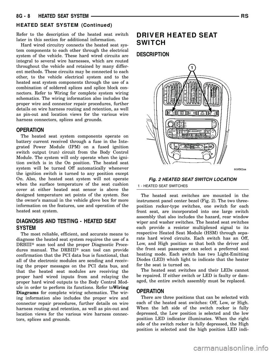
The heated seat switches are mounted in the
instrument panel center bezel (Fig. 2). The two three-
position rocker-type switches, one switch for each
front seat, are incorporated into one large switch
assembly that also includes the hazard, rear window
wiper and washer switches. The heated seat switches
each provide a resistor multiplexed signal to its
respective Heated Seat Module (HSM) through sepa-
rate hard wired circuits. Each switch has an Off,
Low, and High position so that both the driver and
the front seat passenger can select a preferred seat
heating mode. Each switch has two Light-Emitting
Diodes (LED) which light to indicate that the heater
for the seat is turned on.
The heated seat switches and their LEDs cannot
be repaired. If either switch or LED is faulty or dam-
aged, the entire switch assembly must be replaced.
OPERATION
There are three positions that can be selected with
each of the heated seat switches: Off, Low, or High.
When the left side of the switch rocker is fully
depressed, the Low position is selected and the low
position LED indicator illuminates. When the right
side of the switch rocker is fully depressed, the High
position is selected and the high position LED indi-
Fig. 2 HEATED SEAT SWITCH LOCATION
1 - HEATED SEAT SWITCHES
8G - 8 HEATED SEAT SYSTEMRS
HEATED SEAT SYSTEM (Continued)
Page 623 of 2585
Refer toHeated Seat Systemfor more informa-
tion on the heated seat system. Refer toRemote
Keyless Entry Systemin Power Lock Systems for
more information on the RKE system.
Refer toWiring Diagramsfor complete circuit
diagrams. Following are descriptions, theory of oper-
ation, diagnosis/testing procedures and removal/in-
stallation procedures of the major components in the
memory and power seat systems.
OPERATION
OPERATION - POWER SEAT SYSTEM
The power seat system receives battery current
through fuse #22 in the Intelligent Power Module
and a circuit breaker under the front seats, regard-
less of the ignition switch position.
When a power seat switch control knob or knobs
are actuated, a battery feed and a ground path are
applied through the switch contacts to the appropri-
ate power seat track adjuster motor. The selected
adjuster motor operates to move the seat track
through its drive unit in the selected direction until
the switch is released, or until the travel limit of the
seat track is reached. When the switch is moved in
the opposite direction, the battery feed and ground
path to the motor are reversed through the switch
contacts. This causes the adjuster motor to run in the
opposite direction.
No power seat switch should be held applied in any
direction after the seat track has reached its travel
limit. The power seat track each contain a self-reset-
ting circuit breaker to protect them from overload.
However, consecutive or frequent resetting of the cir-
cuit breaker must not be allowed to continue, or the
motor may be damaged. Refer to the owner's manual
in the vehicle glove box for more information on the
features, use and operation of the power seat system.
OPERATION - MEMORY SYSTEM
The Memory Seat Mirror Module (MSMM) receives
battery current through fuse #22 in the Intelligent
Power Module and the power seat system circuit
breaker, located under the driver side front seat near
the rear edge of the seat cushion pan. The memory
system does not operate with the Ignition-Off Draw
(IOD) fuse removed. The MSMM will drive a maxi-
mum of 2 motors at a time in a given direction. If
conflicting directions are requested, the priority for
response will be approximately as follows:
²Seat Track Rearward or Forward
²Seat Front Down or Up
²Seat Rear Down or Up
²Recliner Rearward or ForwardThe inputs from these switches to the MSMM is a
current limited battery source fed by the MSMM.
This protects the MSMM printed circuit board traces
from acting as fuses. All of these switch contact
inputs to the MSMM are normally closed to ground,
except when actuated.
See the owner's manual in the vehicle glove box for
more information on the features, use and operation
of the memory system. For diagnosis of the MSMM,
the PCI data bus, or the other electronic modules on
the PCI data bus that provide inputs and outputs for
the memory system, the use of a DRBIIItscan tool
and the proper Diagnostic Procedures manual are
recommended.
ELECTRONIC VEHICLE INFORMATION CENTER
The Electronic Vehicle Information Center (EVIC)
serves as the user interface for the memory system.
It displays memory system status messages and pro-
vides the user with the means for enabling and dis-
abling the many customer programmable features
available on the vehicle, including those for the mem-
ory system.
See the owner's manual in the vehicle glove box for
more information on the features, use and operation
of the EVIC. Refer toElectronic Vehicle Informa-
tion Centerin Overhead Console Systems for more
information on the EVIC.
DIAGNOSIS AND TESTING
DIAGNOSIS AND TESTING - POWER SEAT
SYSTEM
Following are tests that will help to diagnose the
hard wired components and circuits of the power seat
system. However, if the vehicle is also equipped with
the optional memory system, these tests may not
prove conclusive in the diagnosis of the driver side
power seat. In order to obtain conclusive testing of
the driver side power seat with the memory system
option, the Programmable Communications Interface
(PCI) data bus network and all of the electronic mod-
ules that provide inputs to, or receive outputs from
the memory system components must be checked.
The most reliable, efficient, and accurate means to
diagnose the driver side power seat with the memory
system option requires the use of a DRBIIItscan tool
and the proper Diagnostic Procedures manual. The
DRBIIItscan tool can provide confirmation that the
PCI data bus is functional, that all of the electronic
modules are sending and receiving the proper mes-
sages on the PCI data bus, and that the memory sys-
tem is receiving the proper hard wired inputs and
relaying the proper hard wired outputs to perform its
driver side power seat functions.
8N - 52 POWER SEAT SYSTEMRS
POWER SEAT SYSTEM (Continued)
Page 631 of 2585
ward and rearward directions. The recliner adjust-
ment motor moves the seat back in the forward and
rearward directions.
The power seat track unit cannot be repaired, and
is serviced only as a complete unit. If any component
in this unit is faulty or damaged, the entire power
seat track unit must be replaced.
OPERATION
When a passenger side power seat switch control
knob or knobs are actuated, a battery feed and a
ground path are applied through the switch contacts
to the power seat track or recliner adjuster motor.
The selected adjuster motor operates to move the
seat track or recliner through its drive unit in the
selected direction until the switch is released, or
until the travel limit of the adjuster is reached.
When the switch is moved in the opposite direction,
the battery feed and ground path to the motor are
reversed through the switch contacts. This causes the
adjuster motor to run in the opposite direction.
No power seat switch should be held applied in any
direction after the adjuster has reached its travel
limit. The power seat adjuster motors each contain a
self-resetting circuit breaker to protect them from
overload. However, consecutive or frequent resetting
of the circuit breaker must not be allowed to con-
tinue, or the motor may be damaged.
See the owner's manual in the vehicle glove box for
more information on the power seat switch functions
and the seat adjusting procedures.
DIAGNOSIS AND TESTING - POWER SEAT
TRACK
WARNING: SOME VEHICLES ARE EQUIPPED WITH
SEATBACK MOUNTED AIRBAGS. BEFORE
ATTEMPTING TO DIAGNOSE OR SERVICE ANY
SEAT OR POWER SEAT SYSTEM COMPONENT
YOU MUST FIRST DISCONNECT AND ISOLATE THE
BATTERY NEGATIVE CABLE. THEN WAIT TWO MIN-
UTES FOR THE SYSTEM CAPACITOR TO DIS-
CHARGE BEFORE FURTHER SYSTEM SERVICE.
THIS IS THE ONLY SURE WAY TO DISABLE THE
AIRBAG SYSTEM. FAILURE TO DO SO COULDRESULT IN ACCIDENTAL AIRBAG DEPLOYMENT
AND POSSIBLE PERSONAL INJURY.
Actuate the passenger side power seat switch to
move the power seat track adjuster in each direction.
The power seat track adjuster should move in each of
the selected directions. If a power seat track adjuster
fails to operate in only one direction, move the
adjuster a short distance in the opposite direction
and test again to be certain that the adjuster is not
at its travel limit. If the power seat track adjuster
still fails to operate in only one direction, refer to
Diagnosis and Testing Power Seat Switchin this
section. If the power seat track adjuster fails to oper-
ate in more than one direction, perform the following
tests. For complete circuit diagrams, refer toWiring
Diagrams.
(1) Check the power seat circuit breaker under the
seat. If OK, go to Step 2. If not OK, replace the
faulty power seat circuit breaker.
(2) Check for battery voltage at the power seat cir-
cuit breaker under the seat. If OK, go to Step 3. If
not OK, repair the open fused B(+) circuit to the fuse
in the Intelligent Power Module as required.
(3) Remove the outboard seat cushion side shield
from the seat. Disconnect the seat wire harness con-
nector from the power seat switch connector recepta-
cle. Check for battery voltage at the fused B(+)
circuit cavity of the power seat wire harness connec-
tor for the power seat switch. If OK, go to Step 4. If
not OK, repair the open fused B(+) circuit to the
power seat circuit breaker under the seat as
required.
(4) Check for continuity between the ground cir-
cuit cavity of the power seat wire harness connector
for the power seat switch and a good ground. There
should be continuity. If OK, go to Step 5. If not OK,
repair the open ground circuit to ground as required.
(5) Test the power seat switch. Refer toDiagnosis
and Testing Power Seat Switchin this section. If
the switch tests OK, test the circuits of the power
seat wire harness between the inoperative power seat
track adjuster motor and the power seat switch for
shorts or opens. If the circuits check OK, replace the
faulty power seat track unit. If the circuits are not
OK, repair the power seat wire harness as required.
8N - 60 POWER SEAT SYSTEMRS
PASSENGER POWER SEAT TRACK (Continued)
Page 646 of 2585
Refer toHeated Seat System for more informa-
tion on the heated seat system. Refer to Remote
Keyless Entry System in Power Lock Systems for
more information on the RKE system. Refer to Wiring Diagrams for complete circuit
diagrams. Following are descriptions, theory of oper-
ation, diagnosis/testing procedures and removal/in-
stallation procedures of the major components in the
memory and power seat systems.
OPERATION
OPERATION - POWER SEAT SYSTEM
The power seat system receives battery current
through fuse #22 in the Intelligent Power Module
and a circuit breaker under the front seats, regard-
less of the ignition switch position. When a power seat switch control knob or knobs
are actuated, a battery feed and a ground path are
applied through the switch contacts to the appropri-
ate power seat track adjuster motor. The selected
adjuster motor operates to move the seat track
through its drive unit in the selected direction until
the switch is released, or until the travel limit of the
seat track is reached. When the switch is moved in
the opposite direction, the battery feed and ground
path to the motor are reversed through the switch
contacts. This causes the adjuster motor to run in the
opposite direction. No power seat switch should be held applied in any
direction after the seat track has reached its travel
limit. The power seat track each contain a self-reset-
ting circuit breaker to protect them from overload.
However, consecutive or frequent resetting of the cir-
cuit breaker must not be allowed to continue, or the
motor may be damaged. Refer to the owner's manual
in the vehicle glove box for more information on the
features, use and operation of the power seat system.
OPERATION - MEMORY SYSTEM
The Memory Seat Mirror Module (MSMM) receives
battery current through fuse #22 in the Intelligent
Power Module and the power seat system circuit
breaker, located under the driver side front seat near
the rear edge of the seat cushion pan. The memory
system does not operate with the Ignition-Off Draw
(IOD) fuse removed. The MSMM will drive a maxi-
mum of 2 motors at a time in a given direction. If
conflicting directions are requested, the priority for
response will be approximately as follows: ² Seat Track Rearward or Forward
² Seat Front Down or Up
² Seat Rear Down or Up
² Recliner Rearward or Forward The inputs from these switches to the MSMM is a
current limited battery source fed by the MSMM.
This protects the MSMM printed circuit board traces
from acting as fuses. All of these switch contact
inputs to the MSMM are normally closed to ground,
except when actuated. See the owner's manual in the vehicle glove box for
more information on the features, use and operation
of the memory system. For diagnosis of the MSMM,
the PCI data bus, or the other electronic modules on
the PCI data bus that provide inputs and outputs for
the memory system, the use of a DRBIII tscan tool
and the proper Diagnostic Procedures manual are
recommended.
ELECTRONIC VEHICLE INFORMATION CENTER
The Electronic Vehicle Information Center (EVIC)
serves as the user interface for the memory system.
It displays memory system status messages and pro-
vides the user with the means for enabling and dis-
abling the many customer programmable features
available on the vehicle, including those for the mem-
ory system. See the owner's manual in the vehicle glove box for
more information on the features, use and operation
of the EVIC. Refer to Electronic Vehicle Informa-
tion Center in Overhead Console Systems for more
information on the EVIC.
DIAGNOSIS AND TESTING
DIAGNOSIS AND TESTING - POWER SEAT
SYSTEM
Following are tests that will help to diagnose the
hard wired components and circuits of the power seat
system. However, if the vehicle is also equipped with
the optional memory system, these tests may not
prove conclusive in the diagnosis of the driver side
power seat. In order to obtain conclusive testing of
the driver side power seat with the memory system
option, the Programmable Communications Interface
(PCI) data bus network and all of the electronic mod-
ules that provide inputs to, or receive outputs from
the memory system components must be checked. The most reliable, efficient, and accurate means to
diagnose the driver side power seat with the memory
system option requires the use of a DRBIII tscan tool
and the proper Diagnostic Procedures manual. The
DRBIII tscan tool can provide confirmation that the
PCI data bus is functional, that all of the electronic
modules are sending and receiving the proper mes-
sages on the PCI data bus, and that the memory sys-
tem is receiving the proper hard wired inputs and
relaying the proper hard wired outputs to perform its
driver side power seat functions.
RS POWER SEAT SYSTEM8Ns-9
POWER SEAT SYSTEM (Continued)
Page 654 of 2585
cle. Four bolts secure the bottom of the seat cushion
frame to the upper half of the power seat track unit.
Four additional bolts secure the seat back frame to
the power seat track unit.The passenger side power seat track unit includes
two reversible electric motors that are secured to the
upper half of the track unit. Each motor moves the
seat adjuster through a combination of worm-drive
gearboxes and screw-type drive units. The horizontal
adjustment motor moves the seat track in the for-
ward and rearward directions. The recliner adjust-
ment motor moves the seat back in the forward and
rearward directions. The power seat track unit cannot be repaired, and
is serviced only as a complete unit. If any component
in this unit is faulty or damaged, the entire power
seat track unit must be replaced.
OPERATION
When a passenger side power seat switch control
knob or knobs are actuated, a battery feed and a
ground path are applied through the switch contacts
to the power seat track or recliner adjuster motor.
The selected adjuster motor operates to move the
seat track or recliner through its drive unit in the
selected direction until the switch is released, or
until the travel limit of the adjuster is reached.
When the switch is moved in the opposite direction,
the battery feed and ground path to the motor are
reversed through the switch contacts. This causes the
adjuster motor to run in the opposite direction. No power seat switch should be held applied in any
direction after the adjuster has reached its travel
limit. The power seat adjuster motors each contain a
self-resetting circuit breaker to protect them from
overload. However, consecutive or frequent resetting
of the circuit breaker must not be allowed to con-
tinue, or the motor may be damaged. See the owner's manual in the vehicle glove box for
more information on the power seat switch functions
and the seat adjusting procedures.
DIAGNOSIS AND TESTING - POWER SEAT
TRACK
WARNING: SOME VEHICLES ARE EQUIPPED WITH
SEATBACK MOUNTED AIRBAGS. BEFORE
ATTEMPTING TO DIAGNOSE OR SERVICE ANY
SEAT OR POWER SEAT SYSTEM COMPONENT
YOU MUST FIRST DISCONNECT AND ISOLATE THE BATTERY NEGATIVE CABLE. THEN WAIT TWO MIN-
UTES FOR THE SYSTEM CAPACITOR TO DIS-
CHARGE BEFORE FURTHER SYSTEM SERVICE.
THIS IS THE ONLY SURE WAY TO DISABLE THE
AIRBAG SYSTEM. FAILURE TO DO SO COULD
RESULT IN ACCIDENTAL AIRBAG DEPLOYMENT
AND POSSIBLE PERSONAL INJURY.
Actuate the passenger side power seat switch to
move the power seat track adjuster in each direction.
The power seat track adjuster should move in each of
the selected directions. If a power seat track adjuster
fails to operate in only one direction, move the
adjuster a short distance in the opposite direction
and test again to be certain that the adjuster is not
at its travel limit. If the power seat track adjuster
still fails to operate in only one direction, refer to
Diagnosis and Testing Power Seat Switch in this
section. If the power seat track adjuster fails to oper-
ate in more than one direction, perform the following
tests. For complete circuit diagrams, refer to Wiring
Diagrams .
(1) Check the power seat circuit breaker under the
seat. If OK, go to Step 2. If not OK, replace the
faulty power seat circuit breaker. (2) Check for battery voltage at the power seat cir-
cuit breaker under the seat. If OK, go to Step 3. If
not OK, repair the open fused B(+) circuit to the fuse
in the Intelligent Power Module as required. (3) Remove the outboard seat cushion side shield
from the seat. Disconnect the seat wire harness con-
nector from the power seat switch connector recepta-
cle. Check for battery voltage at the fused B(+)
circuit cavity of the power seat wire harness connec-
tor for the power seat switch. If OK, go to Step 4. If
not OK, repair the open fused B(+) circuit to the
power seat circuit breaker under the seat as
required. (4) Check for continuity between the ground cir-
cuit cavity of the power seat wire harness connector
for the power seat switch and a good ground. There
should be continuity. If OK, go to Step 5. If not OK,
repair the open ground circuit to ground as required. (5) Test the power seat switch. Refer to Diagnosis
and Testing Power Seat Switch in this section. If
the switch tests OK, test the circuits of the power
seat wire harness between the inoperative power seat
track adjuster motor and the power seat switch for
shorts or opens. If the circuits check OK, replace the
faulty power seat track unit. If the circuits are not
OK, repair the power seat wire harness as required.
RS POWER SEAT SYSTEM8Ns-17
PASSENGER POWER SEAT TRACK (Continued)
Page 1292 of 2585
8W-97 POWER DISTRIBUTION SYSTEM
TABLE OF CONTENTS
page page
POWER DISTRIBUTION SYSTEM
DESCRIPTION..........................1
OPERATION............................1
SPECIAL TOOLS
POWER DISTRIBUTION SYSTEMS.........1
INTEGRATED POWER MODULE
DESCRIPTION..........................2
OPERATION............................2
REMOVAL.............................2
INSTALLATION..........................3IOD FUSE
DESCRIPTION..........................3
OPERATION............................3
POWER OUTLET
DESCRIPTION..........................4
OPERATION............................4
DIAGNOSIS AND TESTING
DIAGNOSIS & TESTING - POWER OUTLET . . 4
REMOVAL.............................5
INSTALLATION..........................5
POWER DISTRIBUTION
SYSTEM
DESCRIPTION
This group covers the various standard and
optional power distribution components used on this
model. The power distribution system for this vehicle
consists of the following components:
²Integrated Power Module (IPM)
²Front Control Module (FCM)
²Power Outlets
Refer to Wiring Diagrams for complete circuit sche-
matics.
The power distribution system also incorporates
various types of circuit control and protection fea-
tures, including:
²Automatic resetting circuit breakers
²Blade-type fuses
²Bus bars
²Cartridge fuses
²Circuit splice blocks
²Flashers
²Fusible links
²Relays
Following are general descriptions of the major
components in the power distribution system. See the
owner's manual in the vehicle glove box for more
information on the features and use of all of the
power distribution system components.
OPERATION
The power distribution system for this vehicle is
designed to provide safe, reliable, and centralized dis-
tribution points for the electrical current required to
operate all of the many standard and optional facto-
ry-installed electrical and electronic powertrain,
chassis, safety, security, comfort and convenience sys-
tems. At the same time, the power distribution sys-
tem was designed to provide ready access to these
electrical distribution points for the vehicle techni-
cian to use when conducting diagnosis and repair of
faulty circuits. The power distribution system can
also prove useful for the sourcing of additional elec-
trical circuits that may be required to provide the
electrical current needed to operate many accessories
that the vehicle owner may choose to have installed
in the aftermarket.
SPECIAL TOOLS
POWER DISTRIBUTION SYSTEMS
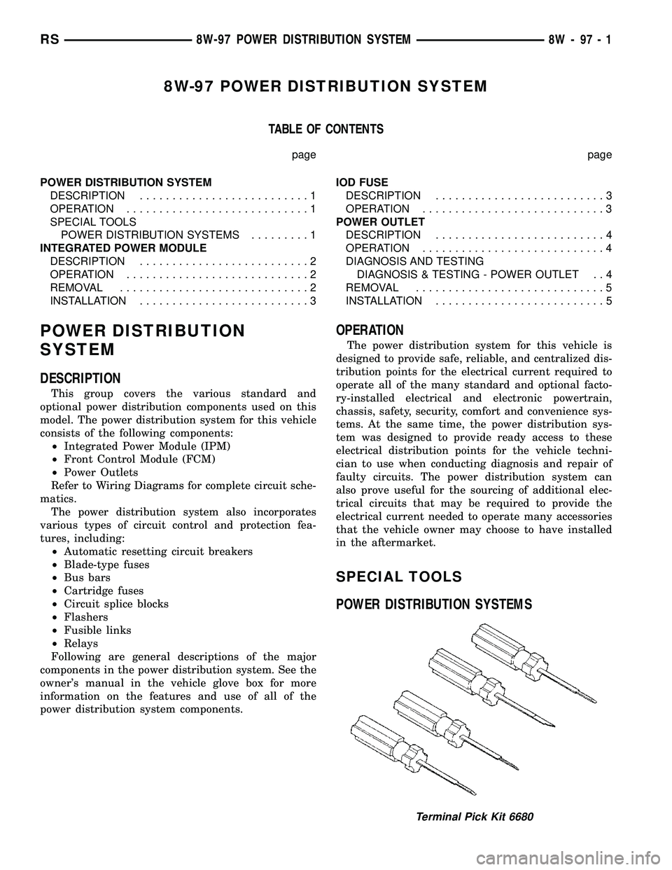
Terminal Pick Kit 6680
RS8W-97 POWER DISTRIBUTION SYSTEM8W-97-1
Page 2415 of 2585
²The normally open terminal (87) provides a bat-
tery current output to the compressor clutch coil
through the compressor clutch relay output circuit
only when the compressor clutch relay coil is ener-
gized.
²The normally closed terminal (87A) is not con-
nected to any circuit in this application, but provides
a battery current output only when the compressor
clutch relay coil is de-energized.
The A/C compressor clutch relay cannot be
repaired and, if faulty or damaged, it must be
replaced. Refer to the appropriate wiring information
for diagnosis and testing of the micro-relay and for
complete HVAC wiring diagrams.
REMOVAL
(1) Disconnect and isolate the negative battery
cable.
(2) Remove the cover from the integrated power
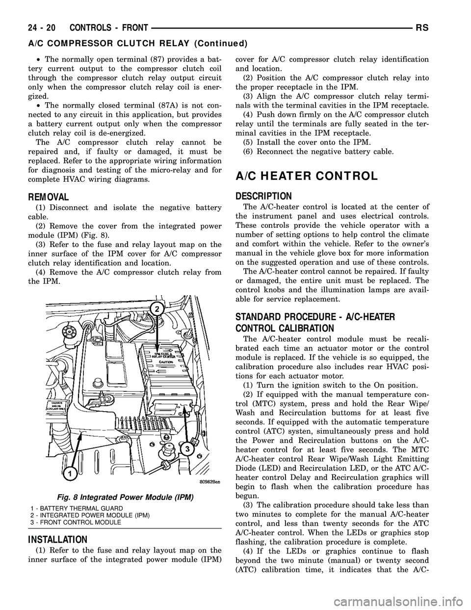
module (IPM) (Fig. 8).
(3) Refer to the fuse and relay layout map on the
inner surface of the IPM cover for A/C compressor
clutch relay identification and location.
(4) Remove the A/C compressor clutch relay from
the IPM.
INSTALLATION
(1) Refer to the fuse and relay layout map on the
inner surface of the integrated power module (IPM)cover for A/C compressor clutch relay identification
and location.
(2) Position the A/C compressor clutch relay into
the proper receptacle in the IPM.
(3) Align the A/C compressor clutch relay termi-
nals with the terminal cavities in the IPM receptacle.
(4) Push down firmly on the A/C compressor clutch
relay until the terminals are fully seated in the ter-
minal cavities in the IPM receptacle.
(5) Install the cover onto the IPM.
(6) Reconnect the negative battery cable.
A/C HEATER CONTROL
DESCRIPTION
The A/C-heater control is located at the center of
the instrument panel and uses electrical controls.
These controls provide the vehicle operator with a
number of setting options to help control the climate
and comfort within the vehicle. Refer to the owner's
manual in the vehicle glove box for more information
on the suggested operation and use of these controls.
The A/C-heater control cannot be repaired. If faulty
or damaged, the entire unit must be replaced. The
control knobs and the illumination lamps are avail-
able for service replacement.
STANDARD PROCEDURE - A/C-HEATER
CONTROL CALIBRATION
The A/C-heater control module must be recali-
brated each time an actuator motor or the control
module is replaced. If the vehicle is so equipped, the
calibration procedure also includes rear HVAC posi-
tions for each actuator motor.
(1) Turn the ignition switch to the On position.
(2) If equipped with the manual temperature con-
trol (MTC) system, press and hold the Rear Wipe/
Wash and Recirculation buttoms for at least five
seconds. If equipped with the automatic temperature
control (ATC) systen, simultaneously press and hold
the Power and Recirculation buttons on the A/C-
heater control for at least five seconds. The MTC
A/C-heater control Rear Wipe/Wash Light Emitting
Diode (LED) and Recirculation LED, or the ATC A/C-
heater control Delay and Recirculation graphics will
begin to flash when the calibration procedure has
begun.
(3) The calibration procedure should take less than
two minutes to complete for the manual A/C-heater
control, and less than twenty seconds for the ATC
A/C-heater control. When the LEDs or graphics stop
flashing, the calibration procedure is complete.
(4) If the LEDs or graphics continue to flash
beyond the two minute (manual) or twenty second
(ATC) calibration time, it indicates that the A/C-
Fig. 8 Integrated Power Module (IPM)
1 - BATTERY THERMAL GUARD
2 - INTEGRATED POWER MODULE (IPM)
3 - FRONT CONTROL MODULE
24 - 20 CONTROLS - FRONTRS
A/C COMPRESSOR CLUTCH RELAY (Continued)