instrument cluster fuse CHRYSLER VOYAGER 2004 Service Manual
[x] Cancel search | Manufacturer: CHRYSLER, Model Year: 2004, Model line: VOYAGER, Model: CHRYSLER VOYAGER 2004Pages: 2585, PDF Size: 62.54 MB
Page 442 of 2585
ULES/POWERTRAIN CONTROL MODULE -
DESCRIPTION) section for more DTC information.
The Check Gauges Lamp (if equipped) or Battery
Lamp monitors:charging system voltage,engine
coolant temperature and engine oil pressure. If an
extreme condition is indicated, the lamp will be illu-
minated. The signal to activate the lamp is sent via
the PCI bus circuits. The lamp is located on the
instrument panel. Refer to the Instrument Cluster
section for additional information.
(If equipped with inlet air temperature sensor) The
PCM uses the inlet air temperature sensor to control
the charge system voltage. This temperature, along
with data from monitored line voltage, is used by the
PCM to vary the battery charging rate. The system
voltage is higher at cold temperatures and is gradu-
ally reduced as the calculated battery temperature
increases.
The ambient temperature sensor is used to control
the battery voltage based upon ambient temperature
(approximation of battery temperature). The PCM
maintains the optimal output of the generator by
monitoring battery voltage and controlling it to a
range of 13.5 - 14.7 volts based on battery tempera-
ture. The system target voltage is 13.5 ± 14.7 volts.
However the actual voltage go below this during
heavy electrical loads and generator speeds. Also the
actual voltage can be lower than the target voltage
between the battery and the battery voltage sense
circuit, approximately 0.2 Ð 0.3 volts.
DIAGNOSIS AND TESTING - ON-BOARD
DIAGNOSTIC SYSTEM
The Powertrain Control Module (PCM) monitors
critical input and output circuits of the charging sys-
tem, making sure they are operational. A Diagnostic
Trouble Code (DTC) is assigned to each input and
output circuit monitored by the OBD system. Some
circuits are checked continuously and some are
checked only under certain conditions.
If the OBD system senses that a monitored circuit
is bad, it will put a DTC into electronic memory. The
DTC will stay in electronic memory as long as the
circuit continues to be bad. The PCM is programmed
to clear the memory after 40 good trip if the problem
does not occur again.
DIAGNOSTIC TROUBLE CODES
A DTC description can be read using the DRBIIIt
scan tool. Refer to the appropriate Powertrain Diag-
nostic Procedures manual for information.
A DTC does not identify which component in a cir-
cuit is bad. Thus, a DTC should be treated as a
symptom, not as the cause for the problem. In some
cases, because of the design of the diagnostic test
procedure, a DTC can be the reason for another DTCto be set. Therefore, it is important that the test pro-
cedures be followed in sequence, to understand what
caused a DTC to be set.
ERASING DIAGNOSTIC TROUBLE CODES
The DRBIIItScan Tool must be used to erase a
DTC.
The following procedures may be used to diagnose
the charging system if:
²the check gauges lamp or battery lamp is illumi-
nated with the engine running
²the voltmeter (if equipped) does not register
properly
²an undercharged or overcharged battery condi-
tion occurs.
Remember that an undercharged battery is often
caused by:
²accessories being left on with the engine not
running
²a faulty or improperly adjusted switch that
allows a lamp to stay on. Refer to Ignition-Off Draw
Test (Refer to 8 - ELECTRICAL/BATTERY SYSTEM/
BATTERY - STANDARD PROCEDURE)
²loose generator belt.
INSPECTION
The Powertrain Control Module (PCM) monitors
critical input and output circuits of the charging sys-
tem, making sure they are operational. A Diagnostic
Trouble Code (DTC) is assigned to each input and
output circuit monitored by the On-Board Diagnostic
(OBD) system. Some charging system circuits are
checked continuously, and some are checked only
under certain conditions.
Refer to Diagnostic Trouble Codes in; Powertrain
Control Module; Electronic Control Modules for more
DTC information. This will include a complete list of
DTC's including DTC's for the charging system.
To perform a complete test of the charging system,
refer to the appropriate Powertrain Diagnostic Proce-
dures service manual and the DRBIIItscan tool.
Perform the following inspections before attaching
the scan tool.
(1) Inspect the battery condition. Refer to the Bat-
tery section (Refer to 8 - ELECTRICAL/BATTERY
SYSTEM - DIAGNOSIS AND TESTING) for proce-
dures.
(2) Inspect condition of battery cable terminals,
battery posts, connections at engine block, starter
solenoid and relay. They should be clean and tight.
Repair as required.
(3) Inspect all fuses in both the fuseblock and
Power Distribution Center (PDC) or IPM (if
equipped) for tightness in receptacles. They should be
properly installed and tight. Repair or replace as
required.
RSCHARGING8F-21
CHARGING (Continued)
Page 478 of 2585
ULES/POWERTRAIN CONTROL MODULE -
DESCRIPTION) section for more DTC information.The Charging system ªBatteryº light indicates
problems with the charging system (voltage too high/
low, generator failure, etc.). If an extreme condition is
indicated, the lamp will be illuminated. The signal to
activate the lamp is sent via the PCI bus circuits.
The lamp is located on the instrument panel. Refer
to the Instrument Cluster section for additional infor-
mation. The PCM uses the ambient air temperature sensor
to control the charge system voltage. This tempera-
ture, along with data from monitored line voltage, is
used by the PCM to vary the battery charging rate.
The system voltage is higher at cold temperatures
and is gradually reduced as the calculated battery
temperature increases. The ambient temperature sensor is used to control
the battery voltage based upon ambient temperature
(approximation of battery temperature). The PCM
maintains the optimal output of the generator by
monitoring battery voltage and controlling it to a
range of 13.5 - 14.7 volts based on battery tempera-
ture.
DIAGNOSIS AND TESTING - ON-BOARD
DIAGNOSTIC SYSTEM
The Powertrain Control Module (PCM) monitors
critical input and output circuits of the charging sys-
tem, making sure they are operational. A Diagnostic
Trouble Code (DTC) is assigned to each input and
output circuit monitored by the OBD system. Some
circuits are checked continuously and some are
checked only under certain conditions. If the OBD system senses that a monitored circuit
is bad, it will put a DTC into electronic memory. The
DTC will stay in electronic memory as long as the
circuit continues to be bad. The PCM is programmed
to clear the memory after 40 good trip if the problem
does not occur again.
DIAGNOSTIC TROUBLE CODES
A DTC description can be read using the DRBIII t
scan tool. Refer to the appropriate Powertrain Diag-
nostic Procedures manual for information. A DTC does not identify which component in a cir-
cuit is bad. Thus, a DTC should be treated as a
symptom, not as the cause for the problem. In some
cases, because of the design of the diagnostic test
procedure, a DTC can be the reason for another DTC
to be set. Therefore, it is important that the test pro-
cedures be followed in sequence, to understand what
caused a DTC to be set. ERASING DIAGNOSTIC TROUBLE CODES
The DRBIII tScan Tool must be used to erase a
DTC. The following procedures may be used to diagnose
the charging system if: ² the check gauges lamp or battery lamp is illumi-
nated with the engine running ² the voltmeter (if equipped) does not register
properly ² an undercharged or overcharged battery condi-
tion occurs. Remember that an undercharged battery is often
caused by: ² accessories being left on with the engine not
running ² a faulty or improperly adjusted switch that
allows a lamp to stay on. Refer to Ignition-Off Draw
Test (Refer t o 8 - ELECTRICAL/BATTERY SYSTEM/
BATTERY - STANDARD PROCEDURE) ² loose generator belt.
INSPECTION The Powertrain Control Module (PCM) monitors
critical input and output circuits of the charging sys-
tem, making sure they are operational. A Diagnostic
Trouble Code (DTC) is assigned to each input and
output circuit monitored by the On-Board Diagnostic
(OBD) system. Some charging system circuits are
checked continuously, and some are checked only
under certain conditions. Refer to Diagnostic Trouble Codes in; Powertrain
Control Module; Electronic Control Modules for more
DTC information. This will include a complete list of
DTC's including DTC's for the charging system. To perform a complete test of the charging system,
refer to the appropriate Powertrain Diagnostic Proce-
dures service manual and the DRBIII tscan tool.
Perform the following inspections before attaching
the scan tool. (1) Inspect the battery condition. Refer to the Bat-
tery section (Refer t o 8 - ELECTRICAL/BATTERY
SYSTEM - DIAGNOSIS AND TESTING) for proce-
dures. (2) Inspect condition of battery cable terminals,
battery posts, connections at engine block, starter
solenoid and relay. They should be clean and tight.
Repair as required. (3) Inspect all fuses in both the fuseblock and
Power Distribution Center (PDC) or IPM (if
equipped) for tightness in receptacles. They should be
properly installed and tight. Repair or replace as
required. (4) Inspect generator mounting bolts for tightness.
Replace or tighten bolts if required. Refer to the Gen-
erator Removal/Installation section of this group for
RS CHARGING8Fs-21
CHARGING (Continued)
Page 902 of 2585

8W-40 INSTRUMENT CLUSTER
Component Page
Airbag Control Module................ 8W-40-2
Body Control Module......... 8W-40-2, 3, 4, 5, 6,
7, 8, 9, 11, 12
Brake Fluid Level Switch.............. 8W-40-9
Clockspring........................ 8W-40-10
Controller Antilock Brake.......... 8W-40-10, 14
Engine Control Module.......... 8W-40-8, 10, 14
Engine Coolant Temp Sensor......... 8W-40-7, 8
Engine Oil Pressure Sensor........... 8W-40-14
Engine Oil Pressure Switch........... 8W-40-14
Front Control Module........ 8W-40-9, 10, 13, 14
Fuel Pump Module................... 8W-40-2
Fuse 24............................ 8W-40-2
G200..................... 8W-40-2, 11, 12, 13
G300.............................. 8W-40-9
Instrument Cluster........ 8W-40-2, 3, 4, 5, 6, 7,
8, 9, 11, 12, 13
Integrated Power Module........ 8W-40-2, 7, 8, 9,
10, 13, 14
Left Front Door Ajar Switch............ 8W-40-3
Left Front Door Lock Motor/Ajar Switch . . 8W-40-3Component Page
Left Sliding Door Control Module........ 8W-40-4
Left Sliding Door Latch Sensing Switch . . . 8W-40-4
Left Sliding Door Lock Motor/Ajar Switch . 8W-40-4
Left Speed Control Switch............ 8W-40-10
Liftgate Ajar Switch.................. 8W-40-3
Liftgate Cinch/Release Motor........... 8W-40-3
Message Center.................. 8W-40-6, 13
Multi-Function Switch................ 8W-40-6
Parking Brake Switch............. 8W-40-11, 12
Powertrain Control Module....... 8W-40-7, 10, 14
Right Front Door Ajar Switch........... 8W-40-3
Right Front Door Lock Motor/Ajar
Switch.......................... 8W-40-3
Right Sliding Door Control Module...... 8W-40-5
Right Sliding Door Latch Sensing Switch . . 8W-40-5
Right Sliding Door Lock Motor/Ajar
Switch.......................... 8W-40-5
Right Speed Control Switch........... 8W-40-10
Traction Control Switch............. 8W-40-7, 8
Vehicle Speed Sensor............... 8W-40-7, 8
Washer Fluid Level Switch............. 8W-40-9
RS8W-40 INSTRUMENT CLUSTER8W-40-1
Page 950 of 2585

8W-44 INTERIOR LIGHTING
Component Page
A/C-Heater Control................... 8W-44-8
Accessory Relay..................... 8W-44-4
Auto Temp Control................... 8W-44-8
Body Control Module..... 8W-44-2, 3, 4, 5, 6, 7, 8
Driver Door Courtesy Lamp............ 8W-44-2
Floor Console Lamp.................. 8W-44-4
Floor Console Power Outlet............ 8W-44-4
Front Cigar Lighter.................. 8W-44-7
Front Control Module................. 8W-44-4
Front Reading Lamps/Switch..... 8W-44-2, 4, 5, 6
Fuse 6............................ 8W-44-4
G200............................ 8W-44-7, 8
G300............................ 8W-44-2, 8
G301........................ 8W-44-2, 3, 5, 6
G302.............................. 8W-44-4
G303.............................. 8W-44-2
Headlamp Switch............ 8W-44-3, 5, 6, 7, 8
Instrument Cluster................... 8W-44-7Component Page
Instrument Panel Switch Bank......... 8W-44-7
Integrated Power Module.............. 8W-44-4
Left Liftgate Flood Lamp.............. 8W-44-2
Left Mid Reading Lamp............... 8W-44-3
Left Rear Reading Lamp.............. 8W-44-3
Left Visor/Vanity Lamp............... 8W-44-6
Overhead Console.................... 8W-44-5
Passenger Door Courtesy Lamp......... 8W-44-2
Radio............................. 8W-44-7
Rear Auto Temp Control Switch......... 8W-44-8
Rear Blower Rear Control Switch........ 8W-44-8
Rear Dome Lamp.................... 8W-44-5
Rear Power Outlet................... 8W-44-4
Right Liftgate Flood Lamp............. 8W-44-2
Right Mid Reading Lamp.............. 8W-44-3
Right Rear Reading Lamp............. 8W-44-3
Right Visor/Vanity Lamp.............. 8W-44-6
RS8W-44 INTERIOR LIGHTING8W-44-1
Page 958 of 2585
8W-45 BODY CONTROL MODULE
Component Page
A/C-Heater Control............... 8W-45-16, 19
Auto Temp Control............... 8W-45-16, 19
Automatic Day/Night Mirror........... 8W-45-11
Body Control Module . . . 8W-45-2, 3, 4, 5, 6, 7, 8, 9,
10, 11, 12, 13, 15, 16, 17, 18, 19, 20
Cd Changer....................... 8W-45-17
Clockspring........................ 8W-45-17
Controller Antilock Brake............. 8W-45-13
Driver Door Courtesy Lamp........... 8W-45-15
Driver Door Lock Switch........... 8W-45-12, 15
Driver Heated Seat Module........... 8W-45-11
Dvd/Cd Changer.................... 8W-45-17
Floor Console Lamp................. 8W-45-13
Front Cigar Lighter................. 8W-45-17
Front Control Module................. 8W-45-3
Front Reading Lamps/Switch....... 8W-45-13, 15
Fuel Pump Module.................. 8W-45-15
Fuse 14............................ 8W-45-3
Fuse 19............................ 8W-45-2
Fuse 20............................ 8W-45-2
Fuse 24............................ 8W-45-2
G301............................ 8W-45-2, 8
Headlamp Switch............. 8W-45-11, 16, 20
Hood Ajar Switch................... 8W-45-12
Ignition Switch...................... 8W-45-3
Instrument Cluster.......... 8W-45-2, 16, 18, 19
Instrument Panel Switch Bank . . 8W-45-10, 11, 17,
19
Integrated Power Module..... 8W-45-2, 3, 5, 6, 13
Left B-Pillar Switch.................. 8W-45-9
Left Cylinder Lock Switch............ 8W-45-10
Left Front Door Ajar Switch............ 8W-45-9
Left Front Door Lock Motor/Ajar
Switch........................ 8W-45-7, 9
Left Liftgate Flood Lamp............. 8W-45-12
Left Mid Reading Lamp............ 8W-45-9, 14
Left Power Mirror................... 8W-45-20
Left Rear Lamp Assembly........... 8W-45-5, 6
Left Rear Reading Lamp........... 8W-45-9, 14
Left Remote Radio Switch............ 8W-45-17
Left Repeater Lamp................. 8W-45-20
Left Sliding Door Control Module..... 8W-45-8, 10
Left Sliding Door Lock Motor........... 8W-45-7Component Page
Left Sliding Door Lock Motor/Ajar
Switch........................ 8W-45-7, 8
Left Visor/Vanity Lamp.............. 8W-45-13
License Lamp....................... 8W-45-8
Liftgate Ajar Switch................. 8W-45-12
Liftgate Cinch/Release Motor.......... 8W-45-12
Memory Set Switch.................. 8W-45-4
Message Center.................... 8W-45-18
Multi-Function Switch............... 8W-45-16
Name Brand Speaker Relay............ 8W-45-3
Overhead Console................. 8W-45-4, 11
Passenger Door Courtesy Lamp........ 8W-45-15
Passenger Door Lock Switch........ 8W-45-12, 15
Passenger Folding Mirror Relay........ 8W-45-20
Passenger Heated Seat Module........ 8W-45-11
Power Folding Mirror Switch.......... 8W-45-20
Power Liftgate Module............. 8W-45-8, 12
Radio............................ 8W-45-17
Rear Auto Temp Control Switch..... 8W-45-10, 19
Rear Blower Rear Control Switch....... 8W-45-10
Rear Dome Lamp.................... 8W-45-9
Rear Wiper Motor.................... 8W-45-8
Right B-Pillar Switch................. 8W-45-9
Right Cylinder Lock Switch........... 8W-45-10
Right Front Door Ajar Switch........... 8W-45-9
Right Front Door Lock Motor/Ajar
Switch........................ 8W-45-7, 9
Right Liftgate Flood Lamp............ 8W-45-12
Right Mid Reading Lamp........... 8W-45-9, 14
Right Power Mirror................. 8W-45-20
Right Rear Lamp Assembly.......... 8W-45-5, 6
Right Rear Reading Lamp.......... 8W-45-9, 14
Right Remote Radio Switch........... 8W-45-17
Right Repeater Lamp................ 8W-45-20
Right Sliding Door Control Module.... 8W-45-8, 10
Right Sliding Door Lock Motor.......... 8W-45-7
Right Sliding Door Lock Motor/Ajar
Switch........................ 8W-45-7, 8
Right Visor/Vanity Lamp............. 8W-45-13
Sentry Key Remote Entry Module....... 8W-45-3
Thatcham Alarm Module............. 8W-45-10
Traction Control Switch.............. 8W-45-17
Trailer Tow Connector................ 8W-45-5
RS8W-45 BODY CONTROL MODULE8W-45-1
Page 978 of 2585
8W-46 MESSAGE CENTER
Component Page
Body Control Module................. 8W-46-2
Fuse 24............................ 8W-46-2
Instrument Cluster................... 8W-46-2Component Page
Integrated Power Module.............. 8W-46-2
Message Center..................... 8W-46-2
RS8W-46 MESSAGE CENTER8W-46-1
Page 1020 of 2585
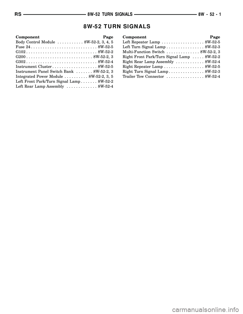
8W-52 TURN SIGNALS
Component Page
Body Control Module........... 8W-52-2, 3, 4, 5
Fuse 24............................ 8W-52-5
G102.............................. 8W-52-2
G200............................ 8W-52-2, 3
G302.............................. 8W-52-4
Instrument Cluster................... 8W-52-5
Instrument Panel Switch Bank....... 8W-52-2, 3
Integrated Power Module.......... 8W-52-2, 3, 5
Left Front Park/Turn Signal Lamp....... 8W-52-2
Left Rear Lamp Assembly............. 8W-52-4Component Page
Left Repeater Lamp.................. 8W-52-5
Left Turn Signal Lamp................ 8W-52-3
Multi-Function Switch.............. 8W-52-2, 3
Right Front Park/Turn Signal Lamp..... 8W-52-2
Right Rear Lamp Assembly............ 8W-52-4
Right Repeater Lamp................. 8W-52-5
Right Turn Signal Lamp............... 8W-52-3
Trailer Tow Connector................ 8W-52-4
RS8W-52 TURN SIGNALS8W-52-1
Page 1112 of 2585

BODY CONTROL MODULE C4 - BLACK/GRAY 34 WAY
CAV CIRCUIT FUNCTION
1- -
2 E12 20OR/GY PANEL LAMPS DRIVER (HVAC)
3- -
4- -
5 G150 22VT/BR INSTRUMENT CLUSTER WAKE UP SENSE
6- -
7 P162 20LG/DG (EXPORT) PASSENGER FOLDING MIRROR RELAY CONTROL
8- -
9 L161 20WT/LG LEFT TURN INDICATOR DRIVER
10 F504 20GY/PK FUSED IGNITION SWITCH OUTPUT (RUN)
11 E14 20OR/TN PANEL LAMPS DRIVER (RADIO)
12 E13 20OR/WT PANEL LAMPS DRIVER (INSTRUMENT CLUSTER)
13 X920 22GY/OR RADIO CONTROL MUX RETURN
14 G900 20VT/DB IGNITION SWITCH SENSE RETURN
15 - -
16 - -
17 L160 20WT/TN RIGHT TURN INDICATOR DRIVER
18 - -
19 - -
20 - -
21 - -
22 G902 22VT/LB MULTI-FUNCTION SWITCH MUX RETURN
23 - -
24 - -
25 - -
26 - -
27 - -
28 - -
29 - -
30 - -
31 - -
32 B27 20DG/WT (TRACTION CONTROL) TRACTION CONTROL SWITCH SENSE
33 P136 20TN/YL (EXPORT) FOLDING MIRROR SWITCH SENSE
34 G26 22VT/OR CHIME DRIVER
RS8W-80 CONNECTOR PIN-OUTS8W-80-17
Page 1176 of 2585

INLET AIR TEMPERATURE SENSOR - BLACK 2 WAY
CAV CIRCUIT FUNCTION
1 K21 18DB/LG INLET AIR TEMPERATURE SENSOR SIGNAL
2 K900 20DB/DG SENSOR GROUND
INPUT SPEED SENSOR - GRAY 2 WAY
CAV CIRCUIT FUNCTION
1 T13 18DG/VT SPEED SENSOR GROUND
2 T52 18DG/WT INPUT SPEED SENSOR SIGNAL
INSTRUMENT CLUSTER - BLACK 13 WAY
CAV CIRCUIT FUNCTION
1 E13 20OR/WT PANEL LAMPS DRIVER
2 L160 20WT/TN (LOWLINE) RIGHT TURN INDICATOR DRIVER
3 G7 20VT/GY (LHD EXPORT) LOW OIL PRESSURE INDICATOR DRIVER
4 G3 20VT/LB (LHD EXPORT) MALFUNCTION INDICATOR LAMP DRIVER
5 L134 20WT/GY (HIGHLINE) HIGH BEAM INDICATOR DRIVER
6 A701 18BR/RD FUSED B(+) (HAZARD)
7 Z108 18BK/LG GROUND
8 L161 20WT/LG (LOWLINE) LEFT TURN INDICATOR DRIVER
9 D25 20WT/VT PCI BUS
10 B25 16DG/WT (LHD EXCEPT EXPORT) PARK BRAKE SWITCH SENSE
10 B25 18DG/WT (LHD EXPORT) PARK BRAKE SWITCH SENSE
10 B25 20DG/WT (RHD) PARK BRAKE SWITCH SENSE
11 G26 22VT/OR CHIME DRIVER
12 G150 22VT/BR INSTRUMENT CLUSTER WAKE UP SENSE
13 Z18 18BK/LB GROUND
INSTRUMENT PANEL SWITCH BANK (EXCEPT HEATED SEATS)-6WAY
CAV CIRCUIT FUNCTION
1 E14 20OR/TN PANEL LAMPS DRIVER
2- -
3 F201 20PK/OR ORC RUN-START DRIVER
4 L91 22WT/DB HAZARD SWITCH SENSE
5- -
6 Z406 20BK/BR GROUND
RS8W-80 CONNECTOR PIN-OUTS8W-80-81
Page 2561 of 2585
INBOARD - 50/50 BENCH - REMOVAL,
SEAT BELT BUCKLE - SECOND ROW.....8O-13
INBOARD - INSTALLATION, SEAT BELT
BUCKLE - FRONT....................8O-12
INBOARD - QUAD BUCKET -
INSTALLATION, SEAT BELT BUCKLE -
FIRST ROW.........................8O-12
INBOARD - QUAD BUCKET - REMOVAL,
SEAT BELT BUCKLE - FIRST ROW.......8O-12
INBOARD - REMOVAL, SEAT BELT
BUCKLE - FRONT....................8O-12
INDICATOR LAMP - DESCRIPTION,
VTSS/SKIS..........................8Q-7
INDICATOR LAMP - OPERATION,
VTSS/SKIS..........................8Q-8
INDICATORS - DIAGNOSIS AND
TESTING, TREAD WEAR..........22-16,22s-8
INFLATION PRESSURES - STANDARD
PROCEDURE, TIRE..............22-16,22s-8
INFO CENTER - DESCRIPTION,
ELECTRONIC VEHICLE.................8M-6
INFO CENTER - INSTALLATION,
ELECTRONIC VEHICLE.................8M-9
INFO CENTER - OPERATION,
ELECTRONIC VEHICLE.................8M-7
INFO CENTER - REMOVAL, ELECTRONIC
VEHICLE............................8M-9
INFRARED TEMPERATURE SENSOR -
DESCRIPTION.......................24-29
INFRARED TEMPERATURE SENSOR -
OPERATION.........................24-29
INITIAL OPERATION - STANDARD
PROCEDURE, POWER STEERING
PUMP.............................19-37
INJECTION SYSTEM - OPERATION.......14-18
INJECTOR - DESCRIPTION, FUEL........14-26
INJECTOR - OPERATION, FUEL..........14-26
INLET AIR TEMPERATURE SENSOR -
DESCRIPTION.......................14-30
INLET FILTER - INSTALLATION..........14-13
INLET FILTER - REMOVAL..............14-13
INLET HOSE - INSTALLATION, HEATER....24-86
INLET HOSE - REMOVAL, HEATER.......24-85
INLET TUBE - 2.4L - DESCRIPTION,
WATER PUMP........................7-35
INLET TUBE - 2.4L - INSTALLATION,
WATER PUMP........................7-35
INLET TUBE - 2.4L - REMOVAL, WATER
PUMP..............................7-35
INLET TUBE - 3.3/3.8L - INSTALLATION,
WATER PUMP........................7-36
INLET TUBE - 3.3/3.8L - REMOVAL,
WATER PUMP........................7-36
INNER - INSTALLATION, CV BOOT.........3-6
INNER - REMOVAL, CV BOOT.............3-6
INNER BELT MOLDING - INSTALLATION,
FRONT DOOR......................23-115
INNER BELT MOLDING - REMOVAL,
FRONT DOOR......................23-115
INNER SEAL - INSTALLATION, HALF
SHAFT.............................21-12
INNER SEAL - REMOVAL, HALF SHAFT . . . 21-12
INNER/OUTER - INSTALLATION, CV
BOOT...............................3-17
INNER/OUTER - REMOVAL, CV BOOT......3-15
INPUT - DESCRIPTION, SPEED SENSOR . 21-239,
21s-140
INPUT - INSTALLATION, SPEED
SENSOR....................21-240,21s-141
INPUT - OPERATION, DATA BUS
COMMUNICATION RECEIVE - PCM.......8E-15
INPUT - OPERATION, IGNITION SENSE -
PCM...............................8E-15
INPUT - OPERATION, SENSOR RETURN -
PCM...............................8E-15
INPUT - OPERATION, SPEED SENSOR . . . 21-240,
21s-140
INPUT - REMOVAL, SPEED SENSOR....21-240,
21s-141
INPUT CLUTCH ASSEMBLY - ASSEMBLY . 21-216,
21s-116
INPUT CLUTCH ASSEMBLY -
DISASSEMBLY...............21-208,21s-107
INPUT FLANGE SEAL - INSTALLATION
.....3-45
INPUT FLANGE SEAL - REMOVAL
.........3-44
INPUT SHAFT - ASSEMBLY
........21-96,21s-5
INPUT SHAFT - DESCRIPTION
.....21-93,21s-1
INPUT SHAFT - DISASSEMBLY
.....21-93,21s-1INPUT SHAFT COVER SEAL -
INSTALLATION.......................21-14
INPUT SHAFT COVER SEAL - REMOVAL . . . 21-13
INPUT SHAFT END SEAL -
INSTALLATION.......................21-16
INPUT SHAFT END SEAL - REMOVAL.....21-15
INPUT SHAFT SEAL - INSTALLATION.....21-18
INPUT SHAFT SEAL - REMOVAL.........21-17
INSIDE HANDLE ACTUATOR -
INSTALLATION.......................23-27
INSIDE HANDLE ACTUATOR - REMOVAL . . 23-27
INSIDE HANDLE CABLE - INSTALLATION . . 23-38
INSIDE HANDLE CABLE - REMOVAL......23-37
INSIDE LATCH HANDLE - INSTALLATION . . 23-34
INSIDE LATCH HANDLE - REMOVAL......23-34
INSPECT, INSPECTION...............21-114
INSTRUMENT CLUSTER - DESCRIPTION . . . 8J-1
INSTRUMENT CLUSTER - OPERATION.....8J-1
INSTRUMENT PANEL - INSTALLATION,
LOWER............................23-69
INSTRUMENT PANEL - REMOVAL,
LOWER............................23-69
INSTRUMENT PANEL ANTENNA CABLE -
INSTALLATION.......................8A-9
INSTRUMENT PANEL ANTENNA CABLE -
REMOVAL...........................8A-8
INSTRUMENT PANEL ASSEMBLY -
INSTALLATION.......................23-66
INSTRUMENT PANEL ASSEMBLY -
REMOVAL............................23-65
INSTRUMENT PANEL CENTER BEZEL -
INSTALLATION.......................23-68
INSTRUMENT PANEL CENTER BEZEL -
REMOVAL..........................23-68
INSTRUMENT PANEL DEMISTER DUCTS
- INSTALLATION.....................24-55
INSTRUMENT PANEL DEMISTER DUCTS
- REMOVAL.........................24-55
INSTRUMENT PANEL DUCTS -
INSTALLATION.......................24-55
INSTRUMENT PANEL DUCTS - REMOVAL . 24-55
INSTRUMENT PANEL END CAP -
INSTALLATION.......................23-68
INSTRUMENT PANEL END CAP -
REMOVAL..........................23-68
INSTRUMENT PANEL OUTLET -
INSTALLATION.......................24-46
INSTRUMENT PANEL OUTLET -
REMOVAL..........................24-45
INSTRUMENT PANEL TOP COVER -
INSTALLATION.......................23-69
INSTRUMENT PANEL TOP COVER -
REMOVAL..........................23-68
INSTRUMENT PANEL TOP PAD
ASSEMBLY - INSTALLATION............23-72
INSTRUMENT PANEL TOP PAD
ASSEMBLY - REMOVAL................23-71
INTAKE MANIFOLD - DESCRIPTION . . 9-144,9-58
INTAKE MANIFOLD - INSTALLATION,
LOWER............................9-149
INTAKE MANIFOLD - INSTALLATION,
UPPER.............................9-147
INTAKE MANIFOLD - LOWER -
CLEANING..........................9-148
INTAKE MANIFOLD - LOWER -
INSPECTION....................9-148,9-60
INTAKE MANIFOLD - LOWER -
INSTALLATION........................9-60
INTAKE MANIFOLD - LOWER - REMOVAL . . 9-60
INTAKE MANIFOLD - REMOVAL, LOWER . . 9-148
INTAKE MANIFOLD - REMOVAL, UPPER . . . 9-145
INTAKE MANIFOLD - UPPER -
INSPECTION.........................9-59
INTAKE MANIFOLD - UPPER -
INSTALLATION........................9-59
INTAKE MANIFOLD - UPPER - REMOVAL . . . 9-58
INTAKE MANIFOLD LEAKS - DIAGNOSIS
AND TESTING...................9-145,9-58
INTAKE MANIFOLD VACUUM PORT
REPAIR - STANDARD PROCEDURE.......9-145
INTAKE PIPE - INSTALLATION, AIR
......24-114
INTAKE PIPE - REMOVAL, AIR
.........24-113
INTAKE/EXHAUST VALVES & SEATS -
CLEANING
.................9-105,9-32,9s-22
INTAKE/EXHAUST VALVES & SEATS -
DESCRIPTION
..............9-104,9-32,9s-21
INTAKE/EXHAUST VALVES & SEATS -
INSPECTION
...................9-105,9s-22INTAKE/EXHAUST VALVES & SEATS -
INSTALLATION..................9-106,9s-23
INTAKE/EXHAUST VALVES & SEATS -
OPERATION....................9-104,9s-21
INTAKE/EXHAUST VALVES & SEATS -
REMOVAL.....................9-105,9s-22
INTEGRAL ANTENNA - EXPORT -
DESCRIPTION, QUARTER GLASS.........8A-9
INTEGRAL ANTENNA - EXPORT -
DIAGNOSIS AND TESTING, QUARTER
GLASS..............................8A-9
INTEGRAL ANTENNA - EXPORT -
OPERATION, QUARTER GLASS...........8A-9
INTEGRATED POWER MODULE -
DESCRIPTION.....................8W-97-2
INTEGRATED POWER MODULE -
INSTALLATION....................8W-97-3
INTEGRATED POWER MODULE -
OPERATION.......................8W-97-2
INTEGRATED POWER MODULE -
REMOVAL........................8W-97-2
INTERACTIVE SPEED CONTROL (4
SPEED EATX ONLY) - OPERATION........8P-2
INTERFACE (PCI) BUS, OPERATION -
PROGRAMMABLE COMMUNICATIONS....14-21
INTERIOR LAMPS, SPECIFICATIONS......8L-20
INTERLOCK - DESCRIPTION, IGNITION....19-17
INTERLOCK SOLENOID - DESCRIPTION,
SHIFT......................21-233,21s-133
INTERLOCK SOLENOID - DIAGNOSIS
AND TESTING, BRAKE/TRANSMISSION
SHIFT......................21-235,21s-135
INTERLOCK SOLENOID - INSTALLATION,
SHIFT.......................21-236,21s-136
INTERLOCK SOLENOID - OPERATION,
SHIFT......................21-233,21s-134
INTERLOCK SOLENOID - REMOVAL,
SHIFT......................21-235,21s-135
INTERLOCK SWITCH - INSTALLATION,
CLUTCH PEDAL.......................6-14
INTERLOCK SWITCH - REMOVAL,
CLUTCH PEDAL.......................6-13
INTERMEDIATE SHAFT - ASSEMBLY....21-107,
21s-17
INTERMEDIATE SHAFT - DESCRIPTION . . 21-100,
21s-9
INTERMEDIATE SHAFT - DISASSEMBLY . 21-100,
21s-10
INTERNATIONAL SYMBOLS -
DESCRIPTION......................Intro.-5
INTERNATIONAL SYMBOLS -
DESCRIPTION.........................0-1
INTRODUCTION - DIAGNOSIS AND
TESTING, ENGINE DIAGNOSIS........9-3,9-76
IOD FUSE - DESCRIPTION...........8W-97-3
IOD FUSE - OPERATION.............8W-97-3
JOINT - DESCRIPTION, LOWER BALL......2-10
JOINT - DIAGNOSIS AND TESTING,
LOWER BALL........................2-10
JOINT - OPERATION, LOWER BALL.......2-10
JOINT MOLDING - INSTALLATION, ROOF . . 23-58
JOINT MOLDING - REMOVAL, ROOF......23-58
JOUNCE BUMPER - DESCRIPTION........2-36
JOUNCE BUMPER - OPERATION..........2-36
JUMP STARTING - STANDARD
PROCEDURE.........................0-27
JUNCTION BLOCK - DESCRIPTION,
NON-ABS.......................5-33,5s-32
JUNCTION BLOCK - INSTALLATION,
NON-ABS.......................5-33,5s-32
JUNCTION BLOCK - OPERATION,
NON-ABS.......................5-33,5s-32
JUNCTION BLOCK - REMOVAL, NON-ABS . . 5-33,
5s-32
KEY - DESCRIPTION, TRANSPONDER.....8Q-6
KEY - OPERATION, TRANSPONDER.......8Q-6
KEY IMMOBILIZER MODULE -
DESCRIPTION, SENTRY................8E-18
KEY IMMOBILIZER MODULE -
INSTALLATION, SENTRY
...............8E-19
KEY IMMOBILIZER MODULE -
OPERATION, SENTRY
.................8E-18
KEY IMMOBILIZER MODULE - REMOVAL,
SENTRY
............................8E-18
KEY REMOTE ENTRY MODULE -
DESCRIPTION, SENTRY
................8Q-3
KEY REMOTE ENTRY MODULE -
DIAGNOSIS AND TESTING, SENTRY
.......8Q-5
18 INDEXRS
Description Group-Page Description Group-Page Description Group-Page