jump start CHRYSLER VOYAGER 2004 Service Manual
[x] Cancel search | Manufacturer: CHRYSLER, Model Year: 2004, Model line: VOYAGER, Model: CHRYSLER VOYAGER 2004Pages: 2585, PDF Size: 62.54 MB
Page 14 of 2585
LUBRICATION & MAINTENANCE
TABLE OF CONTENTS
page page
INTERNATIONAL SYMBOLS
DESCRIPTION..........................1
FLUID TYPES
DESCRIPTION
DESCRIPTION - ENGINE OIL AND
LUBRICANTS.........................1
DESCRIPTION - ENGINE COOLANT........3
DESCRIPTION - FLEXIBLE FUEL ENGINE
OIL .................................3
DESCRIPTION - AUTOMATIC/MANUAL
TRANSAXLE FLUID.....................4
DESCRIPTION - FUEL REQUIREMENTS.....4
DESCRIPTION - FUEL REQUIREMENTS -
DIESEL ENGINE.......................6
DESCRIPTION - ENGINE OIL - DIESEL
ENGINES............................6
DESCRIPTION - AWD REAR DRIVELINE
MODULE FLUIDS......................6
DESCRIPTION - AWD POWER TRANSFER
UNIT FLUID...........................6FLUID CAPACITIES
SPECIFICATIONS - FLUID CAPACITIES.......6
FLUID FILL/CHECK LOCATIONS
DESCRIPTION..........................7
LUBRICATION POINTS
DESCRIPTION..........................7
MAINTENANCE SCHEDULES
DESCRIPTION
DESCRIPTION........................7
DESCRIPTION - EXPORT...............15
DESCRIPTION ± DIESEL ENGINES ±
EXPORT............................24
HOISTING
STANDARD PROCEDURE - HOISTING.......27
JUMP STARTING
STANDARD PROCEDURE - JUMP STARTING . 27
TOWING
STANDARD PROCEDURE - TOWING........29
INTERNATIONAL SYMBOLS
DESCRIPTION
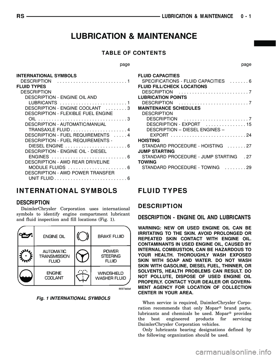
DaimlerChrysler Corporation uses international
symbols to identify engine compartment lubricant
and fluid inspection and fill locations (Fig. 1).
FLUID TYPES
DESCRIPTION
DESCRIPTION - ENGINE OIL AND LUBRICANTS
WARNING: NEW OR USED ENGINE OIL CAN BE
IRRITATING TO THE SKIN. AVOID PROLONGED OR
REPEATED SKIN CONTACT WITH ENGINE OIL.
CONTAMINANTS IN USED ENGINE OIL, CAUSED BY
INTERNAL COMBUSTION, CAN BE HAZARDOUS TO
YOUR HEALTH. THOROUGHLY WASH EXPOSED
SKIN WITH SOAP AND WATER. DO NOT WASH
SKIN WITH GASOLINE, DIESEL FUEL, THINNER, OR
SOLVENTS, HEALTH PROBLEMS CAN RESULT. DO
NOT POLLUTE, DISPOSE OF USED ENGINE OIL
PROPERLY. CONTACT YOUR DEALER OR GOVERN-
MENT AGENCY FOR LOCATION OF COLLECTION
CENTER IN YOUR AREA.
When service is required, DaimlerChrysler Corpo-
ration recommends that only Mopartbrand parts,
lubricants and chemicals be used. Mopartprovides
the best engineered products for servicing
DaimlerChrysler Corporation vehicles.
Only lubricants bearing designations defined by
the following organization should be used.
Fig. 1 INTERNATIONAL SYMBOLS
RSLUBRICATION & MAINTENANCE0-1
Page 40 of 2585
HOISTING
STANDARD PROCEDURE - HOISTING
Refer to Owner's Manual provided with vehicle for
proper emergency jacking procedures.
WARNING: THE HOISTING AND JACK LIFTING
POINTS PROVIDED ARE FOR A COMPLETE VEHI-
CLE. WHEN THE ENGINE OR REAR SUSPENSION
IS REMOVED FROM A VEHICLE, THE CENTER OF
GRAVITY IS ALTERED MAKING SOME HOISTING
CONDITIONS UNSTABLE. PROPERLY SUPPORT OR
SECURE VEHICLE TO HOISTING DEVICE WHEN
THESE CONDITIONS EXIST.
CAUTION: Do not position hoisting device on any
suspension component, including the front suspen-
sion crossmember, the rear leaf springs, and the
rear axle. Do not hoist on the front and rear
bumpers, the lower liftgate crossmember, the lower
radiator crossmember, the down standing flanges
on the sill or the front engine mount.
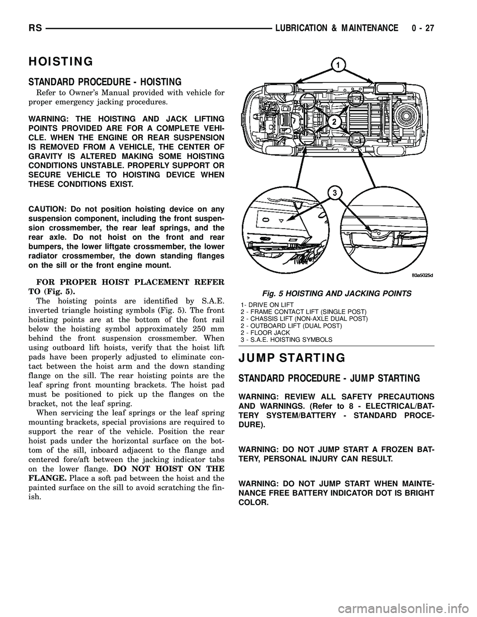
FOR PROPER HOIST PLACEMENT REFER
TO (Fig. 5).
The hoisting points are identified by S.A.E.
inverted triangle hoisting symbols (Fig. 5). The front
hoisting points are at the bottom of the font rail
below the hoisting symbol approximately 250 mm
behind the front suspension crossmember. When
using outboard lift hoists, verify that the hoist lift
pads have been properly adjusted to eliminate con-
tact between the hoist arm and the down standing
flange on the sill. The rear hoisting points are the
leaf spring front mounting brackets. The hoist pad
must be positioned to pick up the flanges on the
bracket, not the leaf spring.
When servicing the leaf springs or the leaf spring
mounting brackets, special provisions are required to
support the rear of the vehicle. Position the rear
hoist pads under the horizontal surface on the bot-
tom of the sill, inboard adjacent to the flange and
centered fore/aft between the jacking indicator tabs
on the lower flange.DO NOT HOIST ON THE
FLANGE.Place a soft pad between the hoist and the
painted surface on the sill to avoid scratching the fin-
ish.
JUMP STARTING
STANDARD PROCEDURE - JUMP STARTING
WARNING: REVIEW ALL SAFETY PRECAUTIONS
AND WARNINGS. (Refer to 8 - ELECTRICAL/BAT-
TERY SYSTEM/BATTERY - STANDARD PROCE-
DURE).
WARNING: DO NOT JUMP START A FROZEN BAT-
TERY, PERSONAL INJURY CAN RESULT.
WARNING: DO NOT JUMP START WHEN MAINTE-
NANCE FREE BATTERY INDICATOR DOT IS BRIGHT
COLOR.
Fig. 5 HOISTING AND JACKING POINTS
1- DRIVE ON LIFT
2 - FRAME CONTACT LIFT (SINGLE POST)
2 - CHASSIS LIFT (NON-AXLE DUAL POST)
2 - OUTBOARD LIFT (DUAL POST)
2 - FLOOR JACK
3 - S.A.E. HOISTING SYMBOLS
RSLUBRICATION & MAINTENANCE0-27
Page 41 of 2585
WARNING: DO NOT ALLOW JUMPER CABLE
CLAMPS TO TOUCH EACH OTHER WHEN CON-
NECTED TO A BOOSTER SOURCE.
WARNING: DO NOT USE OPEN FLAME NEAR BAT-
TERY
WARNING: REMOVE METALLIC JEWELRY WORN
ON HANDS OR WRISTS TO AVOID INJURY BY
ACCIDENTAL ARCING OF BATTERY CURRENT.
WARNING: WHEN USING A HIGH OUTPUT BOOST-
ING DEVICE, DO NOT ALLOW BATTERY VOLTAGE
TO EXCEED 16 VOLTS.
WARNING: REFER TO INSTRUCTIONS PROVIDED
WITH DEVICE BEING USED.
CAUTION: DO NOT ATTEMPT TO PUSH OR TOW
THE VEHICLE TO START IT. THE VEHICLE CANNOT
BE STARTED THIS WAY. PUSHING WITH ANOTHER
VEHICLE MAY DAMAGE THE TRANSAXLE OR THE
REAR OF THE VEHICLE.
(1) Raise hood on disabled vehicle and visually
inspect engine compartment for:
²Battery cable clamp condition, clean if necessary.
²Frozen battery.
²Clear or bright color test indicator, if equipped.
²Generator drive belt condition and tension.
²Fuel fumes or leakage, correct if necessary.
CAUTION: If the cause of starting problem on dis-
abled vehicle is severe, damage to booster vehicle
charging system can result.
(2) When using another vehicle as a booster
source, park the booster vehicle within cable reach.
Turn off all accessories, set the parking brake, place
the automatic transmission in PARK or the manual
transmission in NEUTRAL and turn the ignition
OFF.
(3) On disabled vehicle, place gear selector in park
or neutral and set park brake. Turn off all accesso-
ries.
(4) Connect jumper cables to booster battery. RED
clamp to positive terminal (+). BLACK clamp to neg-
ative terminal (-). DO NOT allow clamps at opposite
end of cables to touch, electrical arc will result.
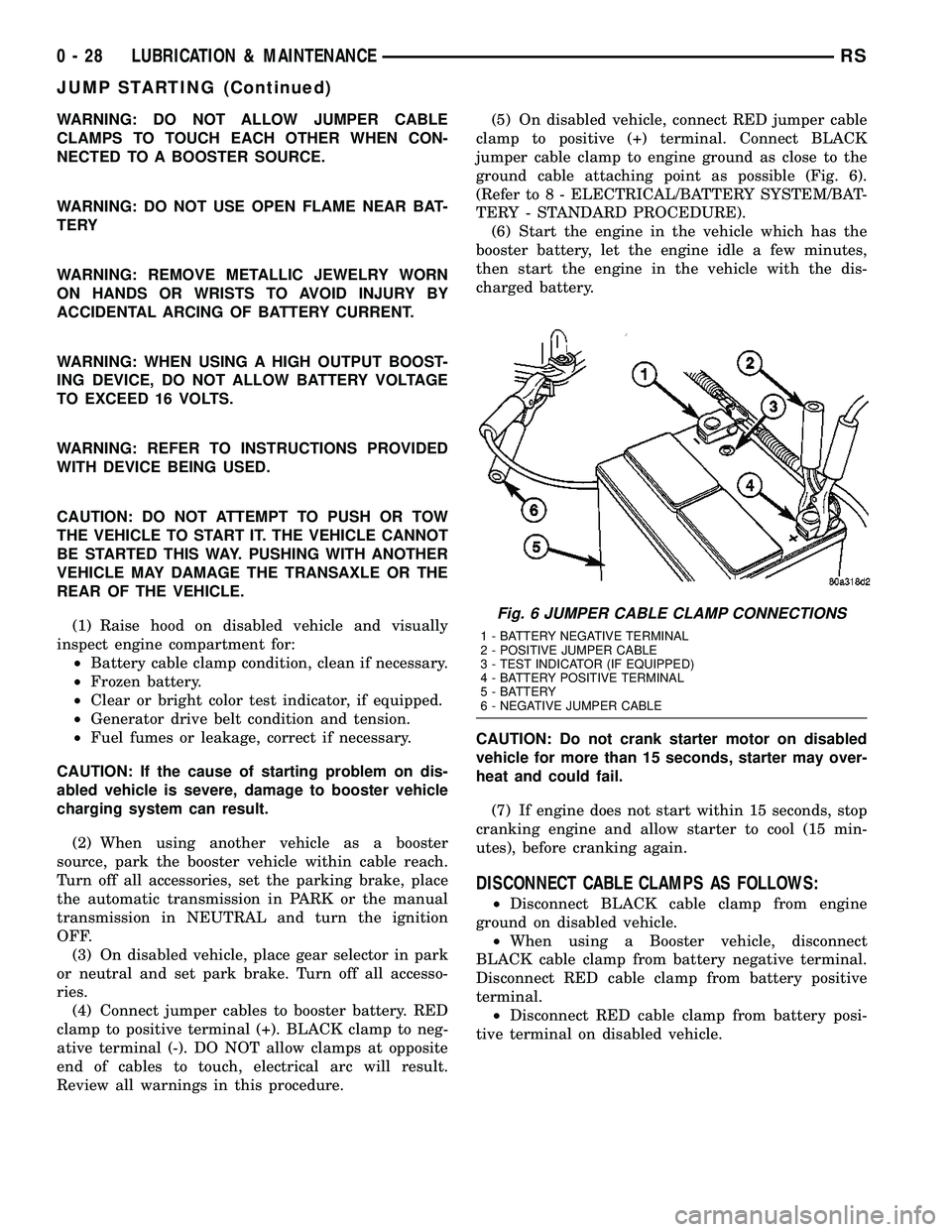
Review all warnings in this procedure.(5) On disabled vehicle, connect RED jumper cable
clamp to positive (+) terminal. Connect BLACK
jumper cable clamp to engine ground as close to the
ground cable attaching point as possible (Fig. 6).
(Refer to 8 - ELECTRICAL/BATTERY SYSTEM/BAT-
TERY - STANDARD PROCEDURE).
(6) Start the engine in the vehicle which has the
booster battery, let the engine idle a few minutes,
then start the engine in the vehicle with the dis-
charged battery.
CAUTION: Do not crank starter motor on disabled
vehicle for more than 15 seconds, starter may over-
heat and could fail.
(7) If engine does not start within 15 seconds, stop
cranking engine and allow starter to cool (15 min-
utes), before cranking again.
DISCONNECT CABLE CLAMPS AS FOLLOWS:
²Disconnect BLACK cable clamp from engine
ground on disabled vehicle.
²When using a Booster vehicle, disconnect
BLACK cable clamp from battery negative terminal.
Disconnect RED cable clamp from battery positive
terminal.
²Disconnect RED cable clamp from battery posi-
tive terminal on disabled vehicle.
Fig. 6 JUMPER CABLE CLAMP CONNECTIONS
1 - BATTERY NEGATIVE TERMINAL
2 - POSITIVE JUMPER CABLE
3 - TEST INDICATOR (IF EQUIPPED)
4 - BATTERY POSITIVE TERMINAL
5 - BATTERY
6 - NEGATIVE JUMPER CABLE
0 - 28 LUBRICATION & MAINTENANCERS
JUMP STARTING (Continued)
Page 423 of 2585
²Battery Holddown- The battery holddown
hardware secures the battery in the battery tray in
the engine compartment.
²Battery Thermowrap- The battery thermow-
rap insulates the battery to protect it from engine
compartment temperature extremes.
²Battery Tray- The battery tray provides a
secure mounting location in the vehicle for the bat-
tery and an anchor point for the battery holddown
hardware.
For battery system maintenance schedules and
jump starting procedure, see the owner's manual in
the vehicle glove box. Optionally, refer to the Lubri-
cation and Maintenance section of this manual for
the recommended battery maintenance schedules and
for the proper battery jump starting procedure. While
battery charging can be considered a maintenance
procedure, the battery charging procedure and
related information are located later in this section of
this service manual. This was done because the bat-
tery must be fully-charged before any battery system
diagnosis or testing procedures can be performed.
OPERATION
The battery system is designed to provide a safe,
efficient, reliable and mobile means of delivering and
storing electrical energy. This electrical energy is
required to operate the engine starting system, as
well as to operate many of the other vehicle acces-
sory systems for limited durations while the engine
and/or the charging system are not operating. The
battery system is also designed to provide a reserve
of electrical energy to supplement the charging sys-
tem for short durations while the engine is running
and the electrical current demands of the vehicle
exceed the output of the charging system. In addition
to delivering, and storing electrical energy for the
vehicle, the battery system serves as a capacitor and
voltage stabilizer for the vehicle electrical system. It
absorbs most abnormal or transient voltages caused
by the switching of any of the electrical components
or circuits in the vehicle.
DIAGNOSIS AND TESTING - BATTERY SYSTEM
The battery, starting, and charging systems in the
vehicle operate with one another and must be tested
as a complete system. In order for the engine to start
and the battery to maintain its charge properly, all of
the components that are used in these systems must
perform within specifications. It is important that
the battery, starting, and charging systems be thor-
oughly tested and inspected any time a battery needs
to be charged or replaced. The cause of abnormal bat-
tery discharge, overcharging or early battery failure
must be diagnosed and corrected before a battery is
replaced and before a vehicle is returned to service.
The service information for these systems has been
separated within this service manual to make it eas-
ier to locate the specific information you are seeking.
However, when attempting to diagnose any of these
systems, it is important that you keep their interde-
pendency in mind.
The diagnostic procedures used for the battery,
starting, and charging systems include the most
basic conventional diagnostic methods, to the more
sophisticated On-Board Diagnostics (OBD) built into
the Powertrain Control Module (PCM). Use of an
induction-type milliampere ammeter, a volt/ohmme-
ter, a battery charger, a carbon pile rheostat (load
tester) and a 12-volt test lamp may be required. All
OBD-sensed systems are monitored by the PCM.
Each monitored circuit is assigned a Diagnostic Trou-
ble Code (DTC). The PCM will store a DTC in elec-
tronic memory for any failure it detects. Refer to
Charging System for the proper charging system on-
board diagnostic test procedures.
MICRO 420 BATTERY TESTER
The Micro 420 automotive battery system tester is
designed to help the dealership technicians diagnose
the cause of a defective battery. Follow the instruc-
tion manual supplied with the tester to properly
diagnose a vehicle. If the instruction manual is not
available refer to the standard procedure in this sec-
tion, which includes the directions for using the
Micro 420 battery tester.
8F - 2 BATTERY SYSTEMRS
BATTERY SYSTEM (Continued)
Page 450 of 2585
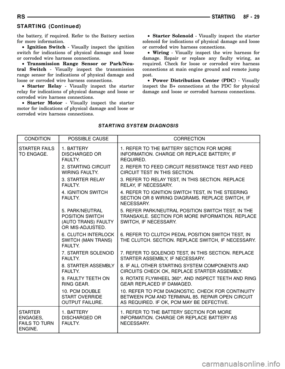
the battery, if required. Refer to the Battery section
for more information.
²Ignition Switch- Visually inspect the ignition
switch for indications of physical damage and loose
or corroded wire harness connections.
²Transmission Range Sensor or Park/Neu-
tral Switch- Visually inspect the transmission
range sensor for indications of physical damage and
loose or corroded wire harness connections.
²Starter Relay- Visually inspect the starter
relay for indications of physical damage and loose or
corroded wire harness connections.
²Starter Motor- Visually inspect the starter
motor for indications of physical damage and loose or
corroded wire harness connections.²Starter Solenoid- Visually inspect the starter
solenoid for indications of physical damage and loose
or corroded wire harness connections.
²Wiring- Visually inspect the wire harness for
damage. Repair or replace any faulty wiring, as
required. Check for loose or corroded wire harness
connections at main engine ground and remote jump
post.
²Power Distribution Center (PDC)- Visually
inspect the B+ connections at the PDC for physical
damage and loose or corroded harness connections.
STARTING SYSTEM DIAGNOSIS
CONDITION POSSIBLE CAUSE CORRECTION
STARTER FAILS
TO ENGAGE.1. BATTERY
DISCHARGED OR
FAULTY.1. REFER TO THE BATTERY SECTION FOR MORE
INFORMATION. CHARGE OR REPLACE BATTERY, IF
REQUIRED.
2. STARTING CIRCUIT
WIRING FAULTY.2. REFER TO FEED CIRCUIT RESISTANCE TEST AND FEED
CIRCUIT TEST IN THIS SECTION.
3. STARTER RELAY
FAULTY.3. REFER TO RELAY TEST, IN THIS SECTION. REPLACE
RELAY, IF NECESSARY.
4. IGNITION SWITCH
FAULTY.4. REFER TO IGNITION SWITCH TEST, IN THE STEERING
SECTION OR 8 WIRING DIAGRAMS. REPLACE SWITCH, IF
NECESSARY.
5. PARK/NEUTRAL
POSITION SWITCH
(AUTO TRANS) FAULTY
OR MIS-ADJUSTED.5. REFER PARK/NEUTRAL POSITION SWITCH TEST, IN THE
TRANSAXLE. SECTION FOR MORE INFORMATION. REPLACE
SWITCH, IF NECESSARY.
6. CLUTCH INTERLOCK
SWITCH (MAN TRANS)
FAULTY.6. REFER TO CLUTCH PEDAL POSITION SWITCH TEST, IN
THE CLUTCH. SECTION. REPLACE SWITCH, IF NECESSARY.
7. STARTER SOLENOID
FAULTY.7. REFER TO SOLENOID TEST, IN THIS SECTION. REPLACE
STARTER ASSEMBLY, IF NECESSARY.
8. STARTER ASSEMBLY
FAULTY.8. IF ALL OTHER STARTING SYSTEM COMPONENTS AND
CIRCUITS CHECK OK, REPLACE STARTER ASSEMBLY.
9. FAULTY TEETH ON
RING GEAR.9. ROTATE FLYWHEEL 360É, AND INSPECT TEETH AND RING
GEAR REPLACED IF DAMAGED.
10. PCM DOUBLE
START OVERRIDE
OUTPUT FAILURE.10. REFER TO PCM DIAGNOSTIC. CHECK FOR CONTINUITY
BETWEEN PCM AND TERMINAL 85. REPAIR OPEN CIRCUIT
AS REQUIRED. IF OK, PCM MAY BE DEFECTIVE.
STARTER
ENGAGES,
FAILS TO TURN
ENGINE.1. BATTERY
DISCHARGED OR
FAULTY.1. REFER TO THE BATTERY SECTION FOR MORE
INFORMATION. CHARGE OR REPLACE BATTERY AS
NECESSARY.
RSSTARTING8F-29
STARTING (Continued)
Page 452 of 2585
(3) Perform a visual inspection of the starter/
starter solenoid for corrosion, loose connections or
faulty wiring.
(4) Locate and remove the starter relay from the
Power Distribution Center (PDC). Refer to the PDC
label for relay identification and location.
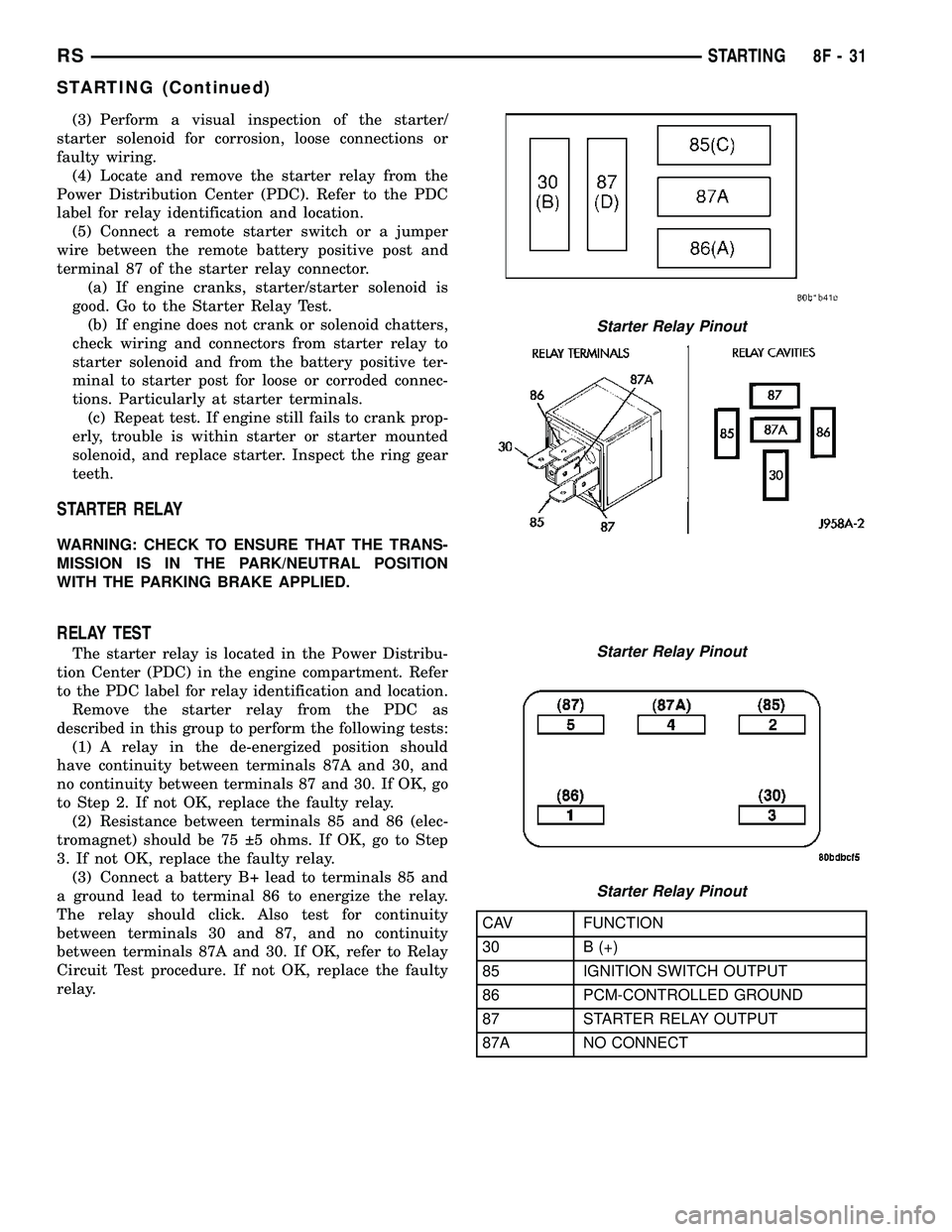
(5) Connect a remote starter switch or a jumper
wire between the remote battery positive post and
terminal 87 of the starter relay connector.
(a) If engine cranks, starter/starter solenoid is
good. Go to the Starter Relay Test.
(b) If engine does not crank or solenoid chatters,
check wiring and connectors from starter relay to
starter solenoid and from the battery positive ter-
minal to starter post for loose or corroded connec-
tions. Particularly at starter terminals.
(c) Repeat test. If engine still fails to crank prop-
erly, trouble is within starter or starter mounted
solenoid, and replace starter. Inspect the ring gear
teeth.
STARTER RELAY
WARNING: CHECK TO ENSURE THAT THE TRANS-
MISSION IS IN THE PARK/NEUTRAL POSITION
WITH THE PARKING BRAKE APPLIED.
RELAY TEST
The starter relay is located in the Power Distribu-
tion Center (PDC) in the engine compartment. Refer
to the PDC label for relay identification and location.
Remove the starter relay from the PDC as
described in this group to perform the following tests:
(1) A relay in the de-energized position should
have continuity between terminals 87A and 30, and
no continuity between terminals 87 and 30. If OK, go
to Step 2. If not OK, replace the faulty relay.
(2) Resistance between terminals 85 and 86 (elec-
tromagnet) should be 75 5 ohms. If OK, go to Step
3. If not OK, replace the faulty relay.
(3) Connect a battery B+ lead to terminals 85 and
a ground lead to terminal 86 to energize the relay.
The relay should click. Also test for continuity
between terminals 30 and 87, and no continuity
between terminals 87A and 30. If OK, refer to Relay
Circuit Test procedure. If not OK, replace the faulty
relay.
CAV FUNCTION
30 B (+)
85 IGNITION SWITCH OUTPUT
86 PCM-CONTROLLED GROUND
87 STARTER RELAY OUTPUT
87A NO CONNECT
Starter Relay Pinout
Starter Relay Pinout
Starter Relay Pinout
RSSTARTING8F-31
STARTING (Continued)
Page 459 of 2585
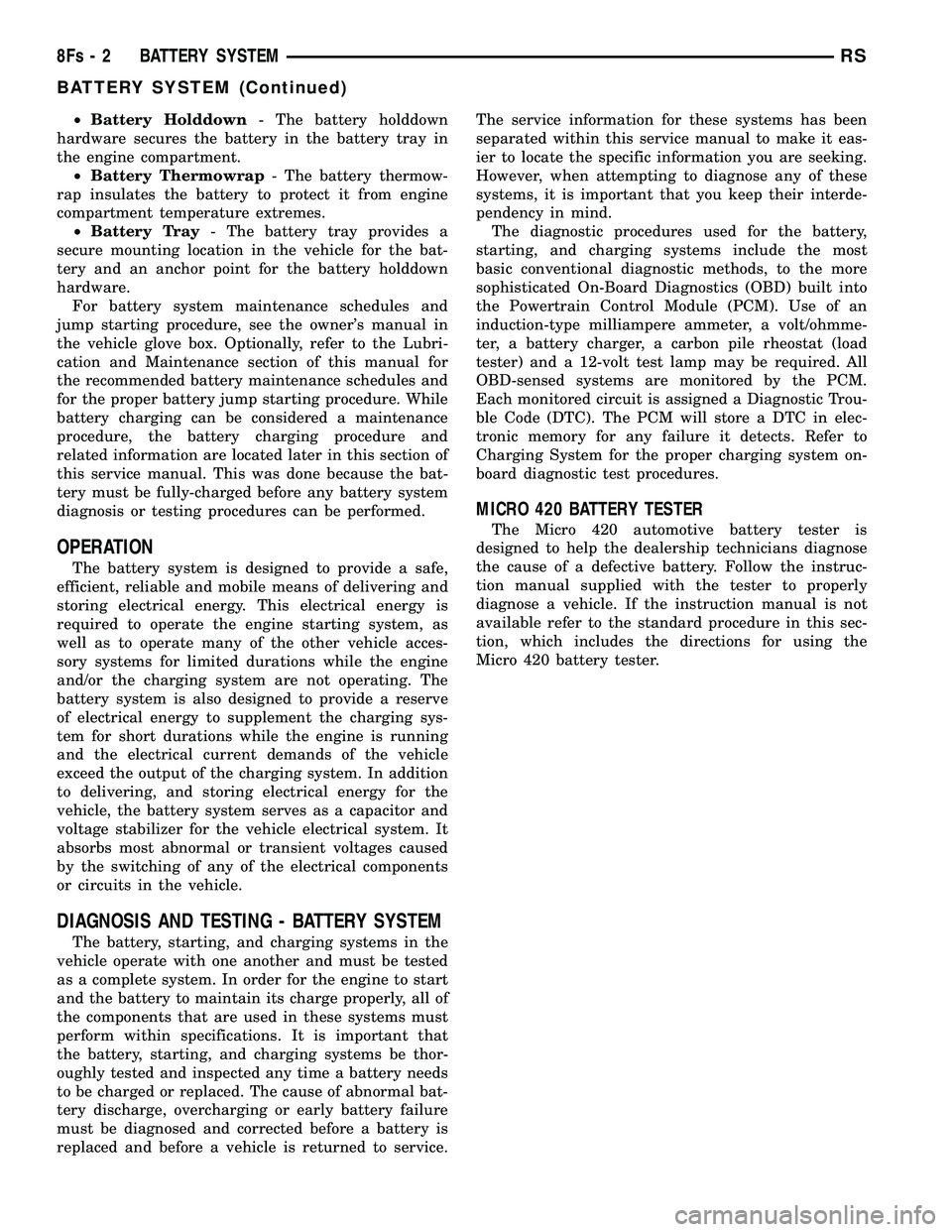
²Battery Holddown - The battery holddown
hardware secures the battery in the battery tray in
the engine compartment. ² Battery Thermowrap - The battery thermow-
rap insulates the battery to protect it from engine
compartment temperature extremes. ² Battery Tray - The battery tray provides a
secure mounting location in the vehicle for the bat-
tery and an anchor point for the battery holddown
hardware. For battery system maintenance schedules and
jump starting procedure, see the owner's manual in
the vehicle glove box. Optionally, refer to the Lubri-
cation and Maintenance section of this manual for
the recommended battery maintenance schedules and
for the proper battery jump starting procedure. While
battery charging can be considered a maintenance
procedure, the battery charging procedure and
related information are located later in this section of
this service manual. This was done because the bat-
tery must be fully-charged before any battery system
diagnosis or testing procedures can be performed.
OPERATION
The battery system is designed to provide a safe,
efficient, reliable and mobile means of delivering and
storing electrical energy. This electrical energy is
required to operate the engine starting system, as
well as to operate many of the other vehicle acces-
sory systems for limited durations while the engine
and/or the charging system are not operating. The
battery system is also designed to provide a reserve
of electrical energy to supplement the charging sys-
tem for short durations while the engine is running
and the electrical current demands of the vehicle
exceed the output of the charging system. In addition
to delivering, and storing electrical energy for the
vehicle, the battery system serves as a capacitor and
voltage stabilizer for the vehicle electrical system. It
absorbs most abnormal or transient voltages caused
by the switching of any of the electrical components
or circuits in the vehicle.
DIAGNOSIS AND TESTING - BATTERY SYSTEM
The battery, starting, and charging systems in the
vehicle operate with one another and must be tested
as a complete system. In order for the engine to start
and the battery to maintain its charge properly, all of
the components that are used in these systems must
perform within specifications. It is important that
the battery, starting, and charging systems be thor-
oughly tested and inspected any time a battery needs
to be charged or replaced. The cause of abnormal bat-
tery discharge, overcharging or early battery failure
must be diagnosed and corrected before a battery is
replaced and before a vehicle is returned to service. The service information for these systems has been
separated within this service manual to make it eas-
ier to locate the specific information you are seeking.
However, when attempting to diagnose any of these
systems, it is important that you keep their interde-
pendency in mind.
The diagnostic procedures used for the battery,
starting, and charging systems include the most
basic conventional diagnostic methods, to the more
sophisticated On-Board Diagnostics (OBD) built into
the Powertrain Control Module (PCM). Use of an
induction-type milliampere ammeter, a volt/ohmme-
ter, a battery charger, a carbon pile rheostat (load
tester) and a 12-volt test lamp may be required. All
OBD-sensed systems are monitored by the PCM.
Each monitored circuit is assigned a Diagnostic Trou-
ble Code (DTC). The PCM will store a DTC in elec-
tronic memory for any failure it detects. Refer to
Charging System for the proper charging system on-
board diagnostic test procedures.
MICRO 420 BATTERY TESTER
The Micro 420 automotive battery tester is
designed to help the dealership technicians diagnose
the cause of a defective battery. Follow the instruc-
tion manual supplied with the tester to properly
diagnose a vehicle. If the instruction manual is not
available refer to the standard procedure in this sec-
tion, which includes the directions for using the
Micro 420 battery tester.
8Fs - 2 BATTERY SYSTEMRS
BATTERY SYSTEM (Continued)
Page 488 of 2585
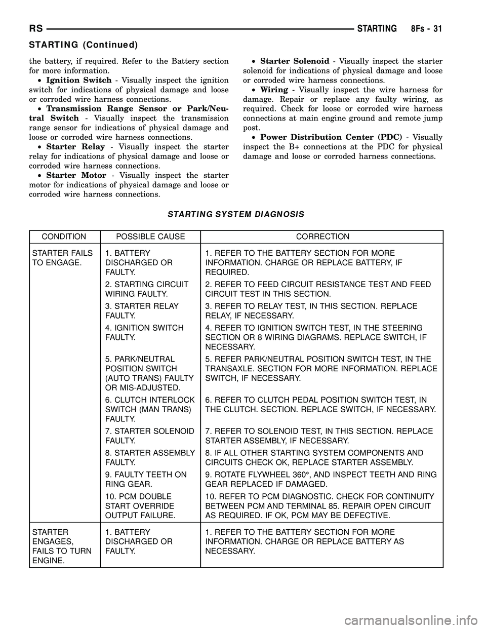
the battery, if required. Refer to the Battery section
for more information.² Ignition Switch - Visually inspect the ignition
switch for indications of physical damage and loose
or corroded wire harness connections. ² Transmission Range Sensor or Park/Neu-
tral Switch - Visually inspect the transmission
range sensor for indications of physical damage and
loose or corroded wire harness connections. ² Starter Relay - Visually inspect the starter
relay for indications of physical damage and loose or
corroded wire harness connections. ² Starter Motor - Visually inspect the starter
motor for indications of physical damage and loose or
corroded wire harness connections. ²
Starter Solenoid - Visually inspect the starter
solenoid for indications of physical damage and loose
or corroded wire harness connections. ² Wiring - Visually inspect the wire harness for
damage. Repair or replace any faulty wiring, as
required. Check for loose or corroded wire harness
connections at main engine ground and remote jump
post. ² Power Distribution Center (PDC) - Visually
inspect the B+ connections at the PDC for physical
damage and loose or corroded harness connections.
STARTING SYSTEM DIAGNOSIS
CONDITION POSSIBLE CAUSE CORRECTION
STARTER FAILS
TO ENGAGE. 1. BATTERY
DISCHARGED OR
FAULTY. 1. REFER TO THE BATTERY SECTION FOR MORE
INFORMATION. CHARGE OR REPLACE BATTERY, IF
REQUIRED.
2. STARTING CIRCUIT
WIRING FAULTY. 2. REFER TO FEED CIRCUIT RESISTANCE TEST AND FEED
CIRCUIT TEST IN THIS SECTION.
3. STARTER RELAY
FAULTY. 3. REFER TO RELAY TEST, IN THIS SECTION. REPLACE
RELAY, IF NECESSARY.
4. IGNITION SWITCH
FAULTY. 4. REFER TO IGNITION SWITCH TEST, IN THE STEERING
SECTION OR 8 WIRING DIAGRAMS. REPLACE SWITCH, IF
NECESSARY.
5. PARK/NEUTRAL
POSITION SWITCH
(AUTO TRANS) FAULTY
OR MIS-ADJUSTED. 5. REFER PARK/NEUTRAL POSITION SWITCH TEST, IN THE
TRANSAXLE. SECTION FOR MORE INFORMATION. REPLACE
SWITCH, IF NECESSARY.
6. CLUTCH INTERLOCK
SWITCH (MAN TRANS)
FAULTY. 6. REFER TO CLUTCH PEDAL POSITION SWITCH TEST, IN
THE CLUTCH. SECTION. REPLACE SWITCH, IF NECESSARY.
7. STARTER SOLENOID
FAULTY. 7. REFER TO SOLENOID TEST, IN THIS SECTION. REPLACE
STARTER ASSEMBLY, IF NECESSARY.
8. STARTER ASSEMBLY
FAULTY. 8. IF ALL OTHER STARTING SYSTEM COMPONENTS AND
CIRCUITS CHECK OK, REPLACE STARTER ASSEMBLY.
9. FAULTY TEETH ON
RING GEAR. 9. ROTATE FLYWHEEL 360É, AND INSPECT TEETH AND RING
GEAR REPLACED IF DAMAGED.
10. PCM DOUBLE
START OVERRIDE
OUTPUT FAILURE. 10. REFER TO PCM DIAGNOSTIC. CHECK FOR CONTINUITY
BETWEEN PCM AND TERMINAL 85. REPAIR OPEN CIRCUIT
AS REQUIRED. IF OK, PCM MAY BE DEFECTIVE.
STARTER
ENGAGES,
FAILS TO TURN
ENGINE. 1. BATTERY
DISCHARGED OR
FAULTY.
1. REFER TO THE BATTERY SECTION FOR MORE
INFORMATION. CHARGE OR REPLACE BATTERY AS
NECESSARY.
RS
STARTING8Fs-31
STARTING (Continued)
Page 490 of 2585
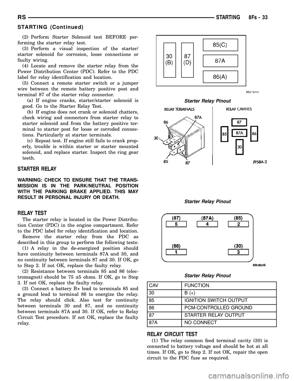
(2) Perform Starter Solenoid test BEFORE per-
forming the starter relay test. (3) Perform a visual inspection of the starter/
starter solenoid for corrosion, loose connections or
faulty wiring. (4) Locate and remove the starter relay from the
Power Distribution Center (PDC). Refer to the PDC
label for relay identification and location. (5) Connect a remote starter switch or a jumper
wire between the remote battery positive post and
terminal 87 of the starter relay connector. (a) If engine cranks, starter/starter solenoid is
good. Go to the Starter Relay Test. (b) If engine does not crank or solenoid chatters,
check wiring and connectors from starter relay to
starter solenoid and from the battery positive ter-
minal to starter post for loose or corroded connec-
tions. Particularly at starter terminals. (c) Repeat test. If engine still fails to crank prop-
erly, trouble is within starter or starter mounted
solenoid, and replace starter. Inspect the ring gear
teeth.
STARTER RELAY
WARNING: CHECK TO ENSURE THAT THE TRANS-
MISSION IS IN THE PARK/NEUTRAL POSITION
WITH THE PARKING BRAKE APPLIED. THIS MAY
RESULT IN PERSONAL INJURY OR DEATH.
RELAY TEST
The starter relay is located in the Power Distribu-
tion Center (PDC) in the engine compartment. Refer
to the PDC label for relay identification and location. Remove the starter relay from the PDC as
described in this group to perform the following tests: (1) A relay in the de-energized position should
have continuity between terminals 87A and 30, and
no continuity between terminals 87 and 30. If OK, go
to Step 2. If not OK, replace the faulty relay. (2) Resistance between terminals 85 and 86 (elec-
tromagnet) should be 75 5 ohms. If OK, go to Step
3. If not OK, replace the faulty relay. (3) Connect a battery B+ lead to terminals 85 and
a ground lead to terminal 86 to energize the relay.
The relay should click. Also test for continuity
between terminals 30 and 87, and no continuity
between terminals 87A and 30. If OK, refer to Relay
Circuit Test procedure. If not OK, replace the faulty
relay.
CAV FUNCTION
30 B (+)
85 IGNITION SWITCH OUTPUT
86 PCM-CONTROLLED GROUND
87 STARTER RELAY OUTPUT
87A NO CONNECT
RELAY CIRCUIT TEST
(1) The relay common feed terminal cavity (30) is
connected to battery voltage and should be hot at all
times. If OK, go to Step 2. If not OK, repair the open
circuit to the PDC fuse as required.
Starter Relay Pinout
Starter Relay Pinout
Starter Relay Pinout
RS STARTING8Fs-33
STARTING (Continued)
Page 2561 of 2585
INBOARD - 50/50 BENCH - REMOVAL,
SEAT BELT BUCKLE - SECOND ROW.....8O-13
INBOARD - INSTALLATION, SEAT BELT
BUCKLE - FRONT....................8O-12
INBOARD - QUAD BUCKET -
INSTALLATION, SEAT BELT BUCKLE -
FIRST ROW.........................8O-12
INBOARD - QUAD BUCKET - REMOVAL,
SEAT BELT BUCKLE - FIRST ROW.......8O-12
INBOARD - REMOVAL, SEAT BELT
BUCKLE - FRONT....................8O-12
INDICATOR LAMP - DESCRIPTION,
VTSS/SKIS..........................8Q-7
INDICATOR LAMP - OPERATION,
VTSS/SKIS..........................8Q-8
INDICATORS - DIAGNOSIS AND
TESTING, TREAD WEAR..........22-16,22s-8
INFLATION PRESSURES - STANDARD
PROCEDURE, TIRE..............22-16,22s-8
INFO CENTER - DESCRIPTION,
ELECTRONIC VEHICLE.................8M-6
INFO CENTER - INSTALLATION,
ELECTRONIC VEHICLE.................8M-9
INFO CENTER - OPERATION,
ELECTRONIC VEHICLE.................8M-7
INFO CENTER - REMOVAL, ELECTRONIC
VEHICLE............................8M-9
INFRARED TEMPERATURE SENSOR -
DESCRIPTION.......................24-29
INFRARED TEMPERATURE SENSOR -
OPERATION.........................24-29
INITIAL OPERATION - STANDARD
PROCEDURE, POWER STEERING
PUMP.............................19-37
INJECTION SYSTEM - OPERATION.......14-18
INJECTOR - DESCRIPTION, FUEL........14-26
INJECTOR - OPERATION, FUEL..........14-26
INLET AIR TEMPERATURE SENSOR -
DESCRIPTION.......................14-30
INLET FILTER - INSTALLATION..........14-13
INLET FILTER - REMOVAL..............14-13
INLET HOSE - INSTALLATION, HEATER....24-86
INLET HOSE - REMOVAL, HEATER.......24-85
INLET TUBE - 2.4L - DESCRIPTION,
WATER PUMP........................7-35
INLET TUBE - 2.4L - INSTALLATION,
WATER PUMP........................7-35
INLET TUBE - 2.4L - REMOVAL, WATER
PUMP..............................7-35
INLET TUBE - 3.3/3.8L - INSTALLATION,
WATER PUMP........................7-36
INLET TUBE - 3.3/3.8L - REMOVAL,
WATER PUMP........................7-36
INNER - INSTALLATION, CV BOOT.........3-6
INNER - REMOVAL, CV BOOT.............3-6
INNER BELT MOLDING - INSTALLATION,
FRONT DOOR......................23-115
INNER BELT MOLDING - REMOVAL,
FRONT DOOR......................23-115
INNER SEAL - INSTALLATION, HALF
SHAFT.............................21-12
INNER SEAL - REMOVAL, HALF SHAFT . . . 21-12
INNER/OUTER - INSTALLATION, CV
BOOT...............................3-17
INNER/OUTER - REMOVAL, CV BOOT......3-15
INPUT - DESCRIPTION, SPEED SENSOR . 21-239,
21s-140
INPUT - INSTALLATION, SPEED
SENSOR....................21-240,21s-141
INPUT - OPERATION, DATA BUS
COMMUNICATION RECEIVE - PCM.......8E-15
INPUT - OPERATION, IGNITION SENSE -
PCM...............................8E-15
INPUT - OPERATION, SENSOR RETURN -
PCM...............................8E-15
INPUT - OPERATION, SPEED SENSOR . . . 21-240,
21s-140
INPUT - REMOVAL, SPEED SENSOR....21-240,
21s-141
INPUT CLUTCH ASSEMBLY - ASSEMBLY . 21-216,
21s-116
INPUT CLUTCH ASSEMBLY -
DISASSEMBLY...............21-208,21s-107
INPUT FLANGE SEAL - INSTALLATION
.....3-45
INPUT FLANGE SEAL - REMOVAL
.........3-44
INPUT SHAFT - ASSEMBLY
........21-96,21s-5
INPUT SHAFT - DESCRIPTION
.....21-93,21s-1
INPUT SHAFT - DISASSEMBLY
.....21-93,21s-1INPUT SHAFT COVER SEAL -
INSTALLATION.......................21-14
INPUT SHAFT COVER SEAL - REMOVAL . . . 21-13
INPUT SHAFT END SEAL -
INSTALLATION.......................21-16
INPUT SHAFT END SEAL - REMOVAL.....21-15
INPUT SHAFT SEAL - INSTALLATION.....21-18
INPUT SHAFT SEAL - REMOVAL.........21-17
INSIDE HANDLE ACTUATOR -
INSTALLATION.......................23-27
INSIDE HANDLE ACTUATOR - REMOVAL . . 23-27
INSIDE HANDLE CABLE - INSTALLATION . . 23-38
INSIDE HANDLE CABLE - REMOVAL......23-37
INSIDE LATCH HANDLE - INSTALLATION . . 23-34
INSIDE LATCH HANDLE - REMOVAL......23-34
INSPECT, INSPECTION...............21-114
INSTRUMENT CLUSTER - DESCRIPTION . . . 8J-1
INSTRUMENT CLUSTER - OPERATION.....8J-1
INSTRUMENT PANEL - INSTALLATION,
LOWER............................23-69
INSTRUMENT PANEL - REMOVAL,
LOWER............................23-69
INSTRUMENT PANEL ANTENNA CABLE -
INSTALLATION.......................8A-9
INSTRUMENT PANEL ANTENNA CABLE -
REMOVAL...........................8A-8
INSTRUMENT PANEL ASSEMBLY -
INSTALLATION.......................23-66
INSTRUMENT PANEL ASSEMBLY -
REMOVAL............................23-65
INSTRUMENT PANEL CENTER BEZEL -
INSTALLATION.......................23-68
INSTRUMENT PANEL CENTER BEZEL -
REMOVAL..........................23-68
INSTRUMENT PANEL DEMISTER DUCTS
- INSTALLATION.....................24-55
INSTRUMENT PANEL DEMISTER DUCTS
- REMOVAL.........................24-55
INSTRUMENT PANEL DUCTS -
INSTALLATION.......................24-55
INSTRUMENT PANEL DUCTS - REMOVAL . 24-55
INSTRUMENT PANEL END CAP -
INSTALLATION.......................23-68
INSTRUMENT PANEL END CAP -
REMOVAL..........................23-68
INSTRUMENT PANEL OUTLET -
INSTALLATION.......................24-46
INSTRUMENT PANEL OUTLET -
REMOVAL..........................24-45
INSTRUMENT PANEL TOP COVER -
INSTALLATION.......................23-69
INSTRUMENT PANEL TOP COVER -
REMOVAL..........................23-68
INSTRUMENT PANEL TOP PAD
ASSEMBLY - INSTALLATION............23-72
INSTRUMENT PANEL TOP PAD
ASSEMBLY - REMOVAL................23-71
INTAKE MANIFOLD - DESCRIPTION . . 9-144,9-58
INTAKE MANIFOLD - INSTALLATION,
LOWER............................9-149
INTAKE MANIFOLD - INSTALLATION,
UPPER.............................9-147
INTAKE MANIFOLD - LOWER -
CLEANING..........................9-148
INTAKE MANIFOLD - LOWER -
INSPECTION....................9-148,9-60
INTAKE MANIFOLD - LOWER -
INSTALLATION........................9-60
INTAKE MANIFOLD - LOWER - REMOVAL . . 9-60
INTAKE MANIFOLD - REMOVAL, LOWER . . 9-148
INTAKE MANIFOLD - REMOVAL, UPPER . . . 9-145
INTAKE MANIFOLD - UPPER -
INSPECTION.........................9-59
INTAKE MANIFOLD - UPPER -
INSTALLATION........................9-59
INTAKE MANIFOLD - UPPER - REMOVAL . . . 9-58
INTAKE MANIFOLD LEAKS - DIAGNOSIS
AND TESTING...................9-145,9-58
INTAKE MANIFOLD VACUUM PORT
REPAIR - STANDARD PROCEDURE.......9-145
INTAKE PIPE - INSTALLATION, AIR
......24-114
INTAKE PIPE - REMOVAL, AIR
.........24-113
INTAKE/EXHAUST VALVES & SEATS -
CLEANING
.................9-105,9-32,9s-22
INTAKE/EXHAUST VALVES & SEATS -
DESCRIPTION
..............9-104,9-32,9s-21
INTAKE/EXHAUST VALVES & SEATS -
INSPECTION
...................9-105,9s-22INTAKE/EXHAUST VALVES & SEATS -
INSTALLATION..................9-106,9s-23
INTAKE/EXHAUST VALVES & SEATS -
OPERATION....................9-104,9s-21
INTAKE/EXHAUST VALVES & SEATS -
REMOVAL.....................9-105,9s-22
INTEGRAL ANTENNA - EXPORT -
DESCRIPTION, QUARTER GLASS.........8A-9
INTEGRAL ANTENNA - EXPORT -
DIAGNOSIS AND TESTING, QUARTER
GLASS..............................8A-9
INTEGRAL ANTENNA - EXPORT -
OPERATION, QUARTER GLASS...........8A-9
INTEGRATED POWER MODULE -
DESCRIPTION.....................8W-97-2
INTEGRATED POWER MODULE -
INSTALLATION....................8W-97-3
INTEGRATED POWER MODULE -
OPERATION.......................8W-97-2
INTEGRATED POWER MODULE -
REMOVAL........................8W-97-2
INTERACTIVE SPEED CONTROL (4
SPEED EATX ONLY) - OPERATION........8P-2
INTERFACE (PCI) BUS, OPERATION -
PROGRAMMABLE COMMUNICATIONS....14-21
INTERIOR LAMPS, SPECIFICATIONS......8L-20
INTERLOCK - DESCRIPTION, IGNITION....19-17
INTERLOCK SOLENOID - DESCRIPTION,
SHIFT......................21-233,21s-133
INTERLOCK SOLENOID - DIAGNOSIS
AND TESTING, BRAKE/TRANSMISSION
SHIFT......................21-235,21s-135
INTERLOCK SOLENOID - INSTALLATION,
SHIFT.......................21-236,21s-136
INTERLOCK SOLENOID - OPERATION,
SHIFT......................21-233,21s-134
INTERLOCK SOLENOID - REMOVAL,
SHIFT......................21-235,21s-135
INTERLOCK SWITCH - INSTALLATION,
CLUTCH PEDAL.......................6-14
INTERLOCK SWITCH - REMOVAL,
CLUTCH PEDAL.......................6-13
INTERMEDIATE SHAFT - ASSEMBLY....21-107,
21s-17
INTERMEDIATE SHAFT - DESCRIPTION . . 21-100,
21s-9
INTERMEDIATE SHAFT - DISASSEMBLY . 21-100,
21s-10
INTERNATIONAL SYMBOLS -
DESCRIPTION......................Intro.-5
INTERNATIONAL SYMBOLS -
DESCRIPTION.........................0-1
INTRODUCTION - DIAGNOSIS AND
TESTING, ENGINE DIAGNOSIS........9-3,9-76
IOD FUSE - DESCRIPTION...........8W-97-3
IOD FUSE - OPERATION.............8W-97-3
JOINT - DESCRIPTION, LOWER BALL......2-10
JOINT - DIAGNOSIS AND TESTING,
LOWER BALL........................2-10
JOINT - OPERATION, LOWER BALL.......2-10
JOINT MOLDING - INSTALLATION, ROOF . . 23-58
JOINT MOLDING - REMOVAL, ROOF......23-58
JOUNCE BUMPER - DESCRIPTION........2-36
JOUNCE BUMPER - OPERATION..........2-36
JUMP STARTING - STANDARD
PROCEDURE.........................0-27
JUNCTION BLOCK - DESCRIPTION,
NON-ABS.......................5-33,5s-32
JUNCTION BLOCK - INSTALLATION,
NON-ABS.......................5-33,5s-32
JUNCTION BLOCK - OPERATION,
NON-ABS.......................5-33,5s-32
JUNCTION BLOCK - REMOVAL, NON-ABS . . 5-33,
5s-32
KEY - DESCRIPTION, TRANSPONDER.....8Q-6
KEY - OPERATION, TRANSPONDER.......8Q-6
KEY IMMOBILIZER MODULE -
DESCRIPTION, SENTRY................8E-18
KEY IMMOBILIZER MODULE -
INSTALLATION, SENTRY
...............8E-19
KEY IMMOBILIZER MODULE -
OPERATION, SENTRY
.................8E-18
KEY IMMOBILIZER MODULE - REMOVAL,
SENTRY
............................8E-18
KEY REMOTE ENTRY MODULE -
DESCRIPTION, SENTRY
................8Q-3
KEY REMOTE ENTRY MODULE -
DIAGNOSIS AND TESTING, SENTRY
.......8Q-5
18 INDEXRS
Description Group-Page Description Group-Page Description Group-Page