ngc CHRYSLER VOYAGER 2004 Service Manual
[x] Cancel search | Manufacturer: CHRYSLER, Model Year: 2004, Model line: VOYAGER, Model: CHRYSLER VOYAGER 2004Pages: 2585, PDF Size: 62.54 MB
Page 394 of 2585
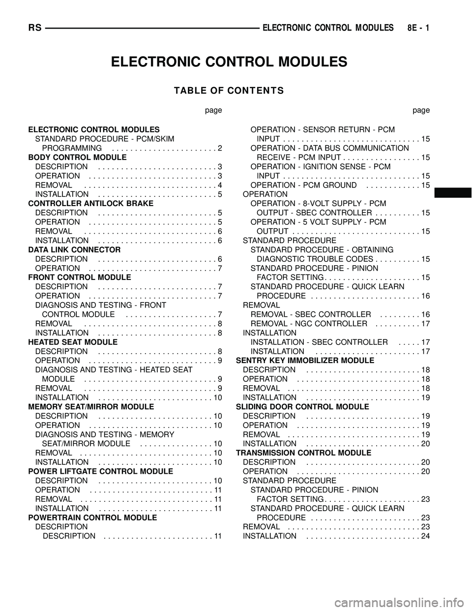
ELECTRONIC CONTROL MODULES
TABLE OF CONTENTS
page page
ELECTRONIC CONTROL MODULES
STANDARD PROCEDURE - PCM/SKIM
PROGRAMMING.......................2
BODY CONTROL MODULE
DESCRIPTION..........................3
OPERATION............................3
REMOVAL.............................4
INSTALLATION..........................5
CONTROLLER ANTILOCK BRAKE
DESCRIPTION..........................5
OPERATION............................5
REMOVAL.............................6
INSTALLATION..........................6
DATA LINK CONNECTOR
DESCRIPTION..........................6
OPERATION............................7
FRONT CONTROL MODULE
DESCRIPTION..........................7
OPERATION............................7
DIAGNOSIS AND TESTING - FRONT
CONTROL MODULE....................7
REMOVAL.............................8
INSTALLATION..........................8
HEATED SEAT MODULE
DESCRIPTION..........................8
OPERATION............................9
DIAGNOSIS AND TESTING - HEATED SEAT
MODULE.............................9
REMOVAL.............................9
INSTALLATION.........................10
MEMORY SEAT/MIRROR MODULE
DESCRIPTION.........................10
OPERATION...........................10
DIAGNOSIS AND TESTING - MEMORY
SEAT/MIRROR MODULE................10
REMOVAL.............................10
INSTALLATION.........................10
POWER LIFTGATE CONTROL MODULE
DESCRIPTION.........................10
OPERATION...........................11
REMOVAL.............................11
INSTALLATION.........................11
POWERTRAIN CONTROL MODULE
DESCRIPTION
DESCRIPTION........................11OPERATION - SENSOR RETURN - PCM
INPUT..............................15
OPERATION - DATA BUS COMMUNICATION
RECEIVE - PCM INPUT.................15
OPERATION - IGNITION SENSE - PCM
INPUT..............................15
OPERATION - PCM GROUND............15
OPERATION
OPERATION - 8-VOLT SUPPLY - PCM
OUTPUT - SBEC CONTROLLER..........15
OPERATION - 5 VOLT SUPPLY - PCM
OUTPUT............................15
STANDARD PROCEDURE
STANDARD PROCEDURE - OBTAINING
DIAGNOSTIC TROUBLE CODES..........15
STANDARD PROCEDURE - PINION
FACTOR SETTING.....................15
STANDARD PROCEDURE - QUICK LEARN
PROCEDURE........................16
REMOVAL
REMOVAL - SBEC CONTROLLER.........16
REMOVAL - NGC CONTROLLER..........17
INSTALLATION
INSTALLATION - SBEC CONTROLLER.....17
INSTALLATION.......................17
SENTRY KEY IMMOBILIZER MODULE
DESCRIPTION.........................18
OPERATION...........................18
REMOVAL.............................18
INSTALLATION.........................19
SLIDING DOOR CONTROL MODULE
DESCRIPTION.........................19
OPERATION...........................19
REMOVAL.............................19
INSTALLATION.........................20
TRANSMISSION CONTROL MODULE
DESCRIPTION.........................20
OPERATION...........................20
STANDARD PROCEDURE
STANDARD PROCEDURE - PINION
FACTOR SETTING.....................23
STANDARD PROCEDURE - QUICK LEARN
PROCEDURE........................23
REMOVAL.............................23
INSTALLATION.........................24
RSELECTRONIC CONTROL MODULES8E-1
Page 405 of 2585
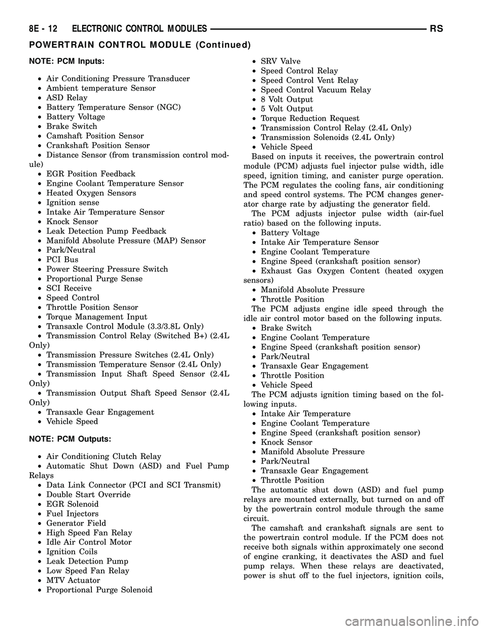
NOTE: PCM Inputs:
²Air Conditioning Pressure Transducer
²Ambient temperature Sensor
²ASD Relay
²Battery Temperature Sensor (NGC)
²Battery Voltage
²Brake Switch
²Camshaft Position Sensor
²Crankshaft Position Sensor
²Distance Sensor (from transmission control mod-
ule)
²EGR Position Feedback
²Engine Coolant Temperature Sensor
²Heated Oxygen Sensors
²Ignition sense
²Intake Air Temperature Sensor
²Knock Sensor
²Leak Detection Pump Feedback
²Manifold Absolute Pressure (MAP) Sensor
²Park/Neutral
²PCI Bus
²Power Steering Pressure Switch
²Proportional Purge Sense
²SCI Receive
²Speed Control
²Throttle Position Sensor
²Torque Management Input
²Transaxle Control Module (3.3/3.8L Only)
²Transmission Control Relay (Switched B+) (2.4L
Only)
²Transmission Pressure Switches (2.4L Only)
²Transmission Temperature Sensor (2.4L Only)
²Transmission Input Shaft Speed Sensor (2.4L
Only)
²Transmission Output Shaft Speed Sensor (2.4L
Only)
²Transaxle Gear Engagement
²Vehicle Speed
NOTE: PCM Outputs:
²Air Conditioning Clutch Relay
²Automatic Shut Down (ASD) and Fuel Pump
Relays
²Data Link Connector (PCI and SCI Transmit)
²Double Start Override
²EGR Solenoid
²Fuel Injectors
²Generator Field
²High Speed Fan Relay
²Idle Air Control Motor
²Ignition Coils
²Leak Detection Pump
²Low Speed Fan Relay
²MTV Actuator
²Proportional Purge Solenoid²SRV Valve
²Speed Control Relay
²Speed Control Vent Relay
²Speed Control Vacuum Relay
²8 Volt Output
²5 Volt Output
²Torque Reduction Request
²Transmission Control Relay (2.4L Only)
²Transmission Solenoids (2.4L Only)
²Vehicle Speed
Based on inputs it receives, the powertrain control
module (PCM) adjusts fuel injector pulse width, idle
speed, ignition timing, and canister purge operation.
The PCM regulates the cooling fans, air conditioning
and speed control systems. The PCM changes gener-
ator charge rate by adjusting the generator field.
The PCM adjusts injector pulse width (air-fuel
ratio) based on the following inputs.
²Battery Voltage
²Intake Air Temperature Sensor
²Engine Coolant Temperature
²Engine Speed (crankshaft position sensor)
²Exhaust Gas Oxygen Content (heated oxygen
sensors)
²Manifold Absolute Pressure
²Throttle Position
The PCM adjusts engine idle speed through the
idle air control motor based on the following inputs.
²Brake Switch
²Engine Coolant Temperature
²Engine Speed (crankshaft position sensor)
²Park/Neutral
²Transaxle Gear Engagement
²Throttle Position
²Vehicle Speed
The PCM adjusts ignition timing based on the fol-
lowing inputs.
²Intake Air Temperature
²Engine Coolant Temperature
²Engine Speed (crankshaft position sensor)
²Knock Sensor
²Manifold Absolute Pressure
²Park/Neutral
²Transaxle Gear Engagement
²Throttle Position
The automatic shut down (ASD) and fuel pump
relays are mounted externally, but turned on and off
by the powertrain control module through the same
circuit.
The camshaft and crankshaft signals are sent to
the powertrain control module. If the PCM does not
receive both signals within approximately one second
of engine cranking, it deactivates the ASD and fuel
pump relays. When these relays are deactivated,
power is shut off to the fuel injectors, ignition coils,
8E - 12 ELECTRONIC CONTROL MODULESRS
POWERTRAIN CONTROL MODULE (Continued)
Page 408 of 2585

OPERATION - SENSOR RETURN - PCM INPUT
The sensor return circuit provides a low electrical
noise ground reference for all of the systems sensors.
The sensor return circuit connects to internal ground
circuits within the Powertrain Control Module
(PCM).
OPERATION - DATA BUS COMMUNICATION
RECEIVE - PCM INPUT
The PCM uses the SCI communication bus to pre-
form engine diagnostics and flash operations. The
transmission side of the PCM uses the SCI commu-
nication bus to flash new software. However, diagnos-
tics is performed via the vehicles J1850 bus for the
transmission side of the PCM.
OPERATION - IGNITION SENSE - PCM INPUT
The ignition sense input informs the Powertrain
Control Module (PCM) that the ignition switch is in
the crank or run position.
OPERATION - PCM GROUND
Ground is provided through multiple pins of the
PCM connector. Depending on the vehicle there may
be as many as two different ground pins. There are
power grounds and sensor grounds.
The power grounds are used to control the ground
side relays, solenoids, ignition coil or injectors. The
signal ground is used for any input that uses sensor
return for ground, and the ground side of any inter-
nal processing component.
The PCM case is shielded to prevent RFI and EMI.
The PCM case is grounded and must be firmly
attached to a good, clean body ground.
Internally all grounds are connected together, how-
ever there is noise suppression on the sensor ground.
For EMI and RFI protection the housing and cover
are also grounded separately from the ground pins.
OPERATION
OPERATION - 8-VOLT SUPPLY - PCM OUTPUT
- SBEC CONTROLLER
The PCM supplies 8 volts to the crankshaft posi-
tion sensor, camshaft position sensor.
OPERATION - 5 VOLT SUPPLY - PCM OUTPUT
The PCM supplies 5 volts to the following sensors:
²A/C pressure transducer
²Ambient Temperature sensor
²Battery temperature
²Camshaft Position Sensor (NGC)
²Crankshaft Position Sensor (NGC)
²Electronic Throttle Control (1.6L)²Engine coolant temperature sensor
²Inlet Air Temperature Sensor
²Knock sensor
²Linear EGR solenoid (if equipped)
²Manifold absolute pressure sensor
²Oil Pressure Switch
²Pedal Position Sensor (1.6L)
²Throttle position sensor
²Vehicle Speed Sensor
STANDARD PROCEDURE
STANDARD PROCEDURE - OBTAINING
DIAGNOSTIC TROUBLE CODES
BULB CHECK
Key on: Bulb illuminated until vehicle starts, as
long as all once per trip (readiness) monitors com-
pleted. If monitors havenotbeen completed, then:
Key on: bulb check for about 5 to 8 seconds, lamp
then flashes if once per trip (readiness) monitors
havenotbeen completed until vehicle is started,
then MIL is extinguished.
OBTAINING DTC'S USING DRB SCAN TOOL
(1) Connect the DRB scan tool to the data link
(diagnostic) connector. This connector is located in
the passenger compartment; at the lower edge of
instrument panel; near the steering column.
(2) Turn the ignition switch on and access the
ªRead Faultº screen.
(3) Record all the DTC's and ªfreeze frameº infor-
mation shown on the DRB scan tool.
(4) To erase DTC's, use the ªErase Trouble Codeº
data screen on the DRB scan tool.Do not erase any
DTC's until problems have been investigated
and repairs have been performed.
STANDARD PROCEDURE - PINION FACTOR
SETTING
NOTE: This procedure must be performed if the
PCM/TCM has been replaced with a NEW or
replacement unit. Failure to perform this procedure
will result in an inoperative or improperly calibrated
speedometer.
The vehicle speed readings for the speedometer are
taken from the output speed sensor. The PCM/TCM
must be calibrated to the different combinations of
equipment (final drive and tires) available. Pinion
Factor allows the technician to set the Powertrain/
Transmission Control Module initial setting so that
the speedometer readings will be correct. To properly
RSELECTRONIC CONTROL MODULES8E-15
POWERTRAIN CONTROL MODULE (Continued)
Page 410 of 2585

REMOVAL - NGC CONTROLLER
The PCM engine control strategy prevents reduced
idle speeds until after the engine operates for 320 km
(200 miles). If the PCM is replaced after 320 km (200
miles) of usage, update the mileage and vehicle iden-
tification number (VIN) in the new PCM. Use the
DRBIIItscan tool to change the millage and VIN in
the PCM. If this step is not done a Diagnostic Trou-
ble Code (DTC) may be set. Refer to the appropriate
Powertrain Diagnostic Manual and the DRBIIItscan
tool.
(1) Turn wheels to the left.
(2) Disconnect the negative battery cable.
(3) Raise vehicle and support.
(4) Remove the left front wheel well splash shield
(Fig. 13).
(5) Unlock and disconnect the electrical connectors
(Fig. 14).
(6) Remove 3 screws from PCM to mounting
bracket.
(7) Remove the PCM.
INSTALLATION
INSTALLATION - SBEC CONTROLLER
(1) Install the PCM.
(2) Install the lower PCM mounting bolt. Tighten
bolt.
(3) Install the 2 upper PCM bracket bolts. Tighten
bolt.
(4) Install the headlamp, refer to the Lamps sec-
tion for more information.
(5) Install the 2 PCM connectors.(6) Install the battery shield, refer to the Battery
section for more information.
(7) Connect the negative battery cable.
INSTALLATION
The PCM engine control strategy prevents reduced
idle speeds until after the engine operates for 320 km
(200 miles). If the PCM is replaced after 320 km (200
miles) of usage, update the mileage and vehicle iden-
tification number (VIN) in the new PCM. Use the
DRBIIItscan tool to change the millage and VIN in
the PCM. If this step is not done a diagnostic trouble
code (DTC) may be set and SKIM must be done or
car will not start if it is a SKIM equipped car. If a
SKIM car you must do a secret key transfer also.
NGC CONTROLLER LOCATION
Fig. 13 SPLASH SHIELD
Fig. 14 NGC CONTROLLER
RSELECTRONIC CONTROL MODULES8E-17
POWERTRAIN CONTROL MODULE (Continued)
Page 444 of 2585
SPECIAL TOOLS
BATTERY TEMPERATURE
SENSOR
DESCRIPTION
(NGC Vehicles) The PCM incorporates a Battery
Temperature Sensor (BTS) on its circuit board.
OPERATION
The PCM uses the temperature of the battery area
to control the charge system voltage. This tempera-
ture, along with data from monitored line voltage, is
used by the PCM to vary the battery charging rate.
The system voltage is higher at cold temperatures
and is gradually reduced as temperature around the
battery increases.
(NGC Vehicles) The ambient temperature sensor is
used to control the battery voltage based upon ambi-
ent temperature (approximation of battery tempera-
ture). The PCM maintains the optimal output of the
generator by monitoring battery voltage and control-
ling it to a range of 13.5 - 14.7 volts based on battery
temperature. The system target voltage is 13.5 ± 14.7
volts. However the actual voltage go below this dur-
ing heavy electrical loads and generator speeds. Also
the actual voltage can be lower than the target volt-
age between the battery and the battery voltage
sense circuit, approximately 0.2 Ð 0.3 volts.
The battery temperature sensor is also used for
OBD II diagnostics. Certain faults and OBD II mon-
itors are either enabled or disabled depending upon
the battery temperature sensor input (example: dis-
able purge and EGR, enable LDP). Most OBD II
monitors are disabled below 20ÉF.
REMOVAL
The battery temperature sensor is not serviced sep-
arately. If replacement is necessary, the PCM must
be replaced.
GENERATOR
DESCRIPTION
The generator is belt-driven by the engine. The
generator produces DC voltage at the B+ terminal. If
the generator is failed, the generator assembly sub-
components (generator and decoupler pulley) must be
inspected for individual failure and replaced accord-
ingly.
OPERATION
As the energized rotor begins to rotate within the
generator, the spinning magnetic field induces a cur-
rent into the windings of the stator coil. Once the
generator begins producing sufficient current, it also
provides the current needed to energize the rotor.
The Y type stator winding connections deliver the
induced AC current to 3 positive and 3 negative
diodes for rectification. From the diodes, rectified DC
current is delivered to the vehicles electrical system
through the generator, battery, and ground terminals.
Excessive or abnormal noise emitting from the gen-
erator may be caused by:
²Worn, loose or defective bearings
²Loose or defective drive pulley (2.4L) or decou-
pler (3.3/3.8L)
²Incorrect, worn, damaged or misadjusted drive
belt
²Loose mounting bolts
²Misaligned drive pulley
²Defective stator or diode
²Damaged internal fins
REMOVAL
REMOVAL - 2.4L
(1) Release hood latch and open hood.
(2) Disconnect battery negative cable.
(3) Disconnect the Inlet Air Temperature sensor.
(4) Remove the Air Box, refer to the Engine/Air
Cleaner for more information.
(5) Remove the EVAP Purge solenoid from its
bracket and reposition.
(6) Disconnect the push-in field wire connector
from back of generator.
(7) Remove nut holding B+ wire terminal to back
of generator.
(8) Separate B+ terminal from generator.
(9) Remove accessory drive belt, refer to the Cool-
ing System section for proper procedures.
(10) Remove the generator.
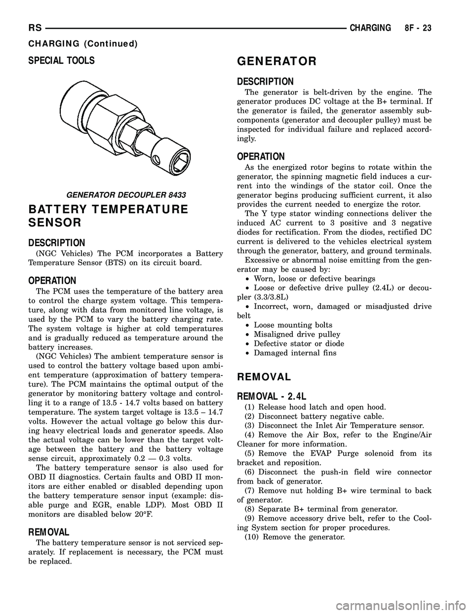
GENERATOR DECOUPLER 8433
RSCHARGING8F-23
CHARGING (Continued)
Page 448 of 2585

VOLTAGE REGULATOR
DESCRIPTION
The Electronic Voltage Regulator (EVR) is not a
separate component. It is actually a voltage regulat-
ing circuit located within the Powertrain Control
Module (PCM). The EVR is not serviced separately. If
replacement is necessary, the PCM must be replaced.
OPERATION
The amount of DC current produced by the gener-
ator is controlled by EVR circuitry contained within
the PCM. This circuitry is connected in series with
the generators second rotor field terminal and its
ground.
Voltage is regulated by cycling the ground path on
SBEC vehicles or the power side on the NGC vehi-
cles, to control the strength of the rotor magnetic
field. The EVR circuitry monitors system line voltage
at the PDC and calculated battery temperature or
inlet air temperature sensor (refer to Inlet Air Tem-
perature Sensor, if equipped, for more information ).
It then determines a target charging voltage. If
sensed battery voltage is lower than the target volt-
age, the PCM feeds the field winding until sensed
battery voltage is at the target voltage. A circuit in
the PCM cycles the feed side of the generator field at
250 times per second (250Hz), but has the capability
to feed the field control wire 100% of the time (full
field) to achieve the target voltage. If the charging
rate cannot be monitored (limp-in), a duty cycle of
20% is used by the PCM in order to have some gen-
erator output. Also refer to Charging System Opera-
tion for additional information.
Fig. 7 DECOUPLER INSTALLATION (Litens)
RSCHARGING8F-27
GENERATOR DECOUPLER PULLEY (Continued)
Page 480 of 2585
SPECIAL TOOLS
BATTERY TEMPERATURE
SENSOR
DESCRIPTION
(NGC Vehicles) The PCM incorporates a Battery
Temperature Sensor (BTS) on its circuit board.
OPERATION
The PCM uses the temperature of the battery area
to control the charge system voltage. This tempera-
ture, along with data from monitored line voltage, is
used by the PCM to vary the battery charging rate.
The system voltage is higher at cold temperatures
and is gradually reduced as temperature around the
battery increases. For vehicles with 1.6L engine, there is no physical
battery temp sensor in place to detect battery temp.
Rather, an algorithm buit in PCM is employed to pre-
dict battery temp using inlet air temp, vehicle speed,
and coolant temp, among other signals. The PCM
maintains the optimal output of the generator by
monitoring battery voltage and controlling it to a
range of 13.5 - 14.7 volts based on battery tempera-
ture. The system target voltage is 13.5 ± 14.7 volts.
However the actual voltage go below this during
heavy electrical loads and generator speeds. Also the
actual voltage can be lower than the target voltage
between the battery and the battery voltage sense
circuit, approximately 0.2 Ð 0.3 volts. The battery temperature sensor is also used for
OBD II diagnostics. Certain faults and OBD II mon-
itors are either enabled or disabled depending upon
the battery temperature sensor input (example: dis-
able purge and EGR, enable LDP). Most OBD II
monitors are disabled below 20ÉF.
REMOVAL
The battery temperature sensor is not serviced sep-
arately. If replacement is necessary, the PCM must
be replaced.
GENERATOR
DESCRIPTION
The generator is belt-driven by the engine. The
generator produces DC voltage at the B+ terminal. If
the generator is failed, the generator assembly sub-
components (generator and decoupler pulley) must be
inspected for individual failure and replaced accord-
ingly.
OPERATION
As the energized rotor begins to rotate within the
generator, the spinning magnetic field induces a cur-
rent into the windings of the stator coil. Once the
generator begins producing sufficient current, it also
provides the current needed to energize the rotor. The Y type stator winding connections deliver the
induced AC current to 3 positive and 3 negative
diodes for rectification. From the diodes, rectified DC
current is delivered to the vehicles electrical system
through the generator, battery, and ground terminals. Excessive or abnormal noise emitting from the gen-
erator may be caused by: ² Worn, loose or defective bearings
² Loose or defective drive pulley (2.4L) or decou-
pler (3.3/3.8L) ² Incorrect, worn, damaged or misadjusted drive
belt ² Loose mounting bolts
² Misaligned drive pulley
² Defective stator or diode
² Damaged internal fins
REMOVAL
REMOVAL - 2.4L
(1) Release hood latch and open hood.
(2) Disconnect battery negative cable.
(3) Disconnect the Inlet Air Temperature sensor.
(4) Remove the Air Box, refer to the Engine/Air
Cleaner for more information. (5) Remove the EVAP Purge solenoid from its
bracket and reposition. (6) Disconnect the push-in field wire connector
from back of generator. (7) Remove nut holding B+ wire terminal to back
of generator. (8) Separate B+ terminal from generator.
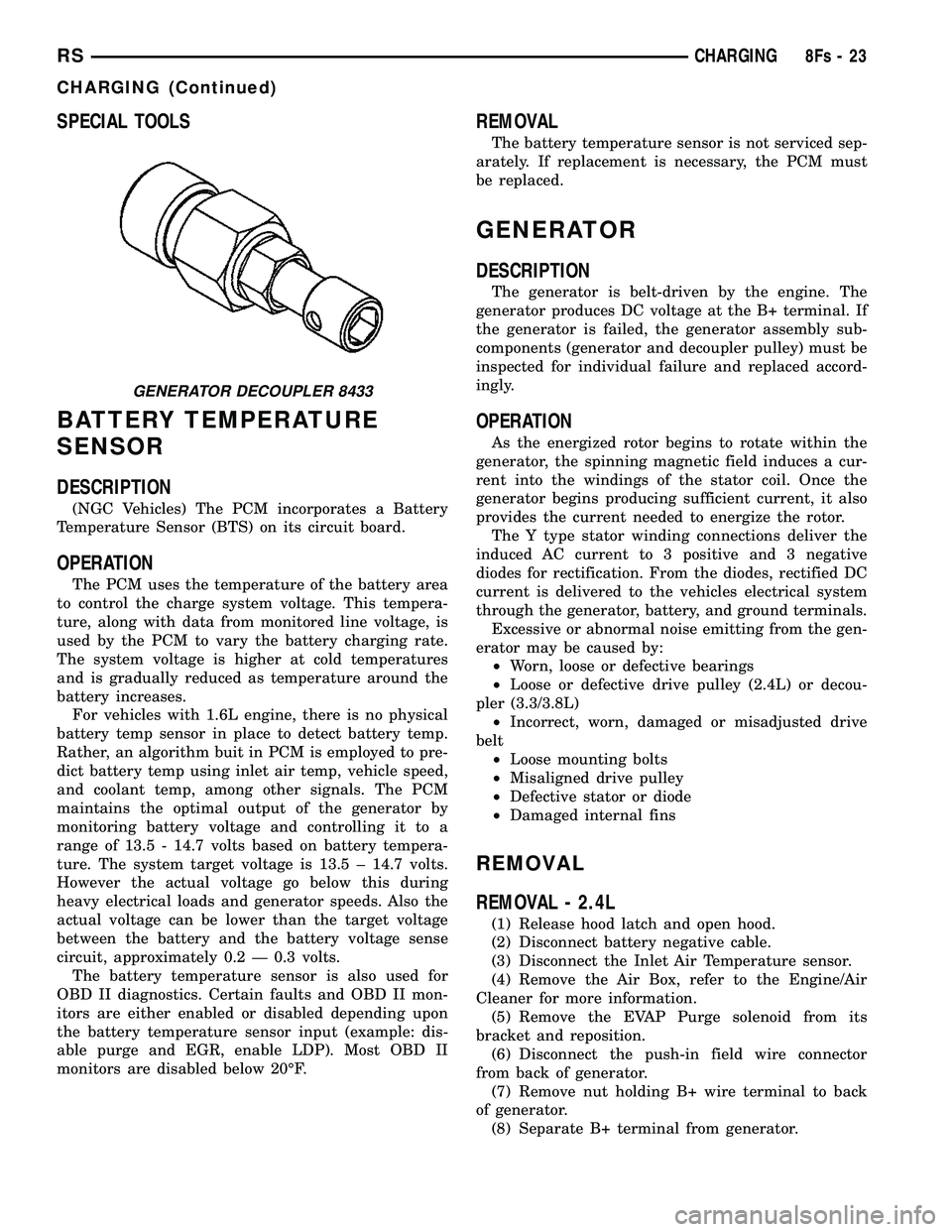
GENERATOR DECOUPLER 8433
RS CHARGING8Fs-23
CHARGING (Continued)
Page 486 of 2585
VOLTAGE REGULATOR
DESCRIPTION
The Electronic Voltage Regulator (EVR) is not a
separate component. It is actually a voltage regulat-
ing circuit located within the Powertrain Control
Module (PCM). The EVR is not serviced separately. If
replacement is necessary, the PCM must be replaced.
OPERATION
The amount of DC current produced by the gener-
ator is controlled by EVR circuitry contained within
the PCM. This circuitry is connected in series with
the generators second rotor field terminal and its
ground. Voltage is regulated within the PCM on the NGC
vehicles, to control the strength of the rotor magnetic
field. The EVR circuitry monitors system line voltage
at the PDC and calculated battery temperature or
inlet air temperature sensor (refer to Inlet Air Tem-
perature Sensor, if equipped, for more information ).
It then determines a target charging voltage. If
sensed battery voltage is lower than the target volt-
age, the PCM feeds the field winding until sensed
battery voltage is at the target voltage. A circuit in
the PCM cycles the feed side of the generator field at
250 times per second (250Hz), but has the capability
to feed the field control wire 100% of the time (full
field) to achieve the target voltage. If the charging
rate cannot be monitored (limp-in), a duty cycle of
20% is used by the PCM in order to have some gen-
erator output. Also refer to Charging System Opera-
tion for additional information.
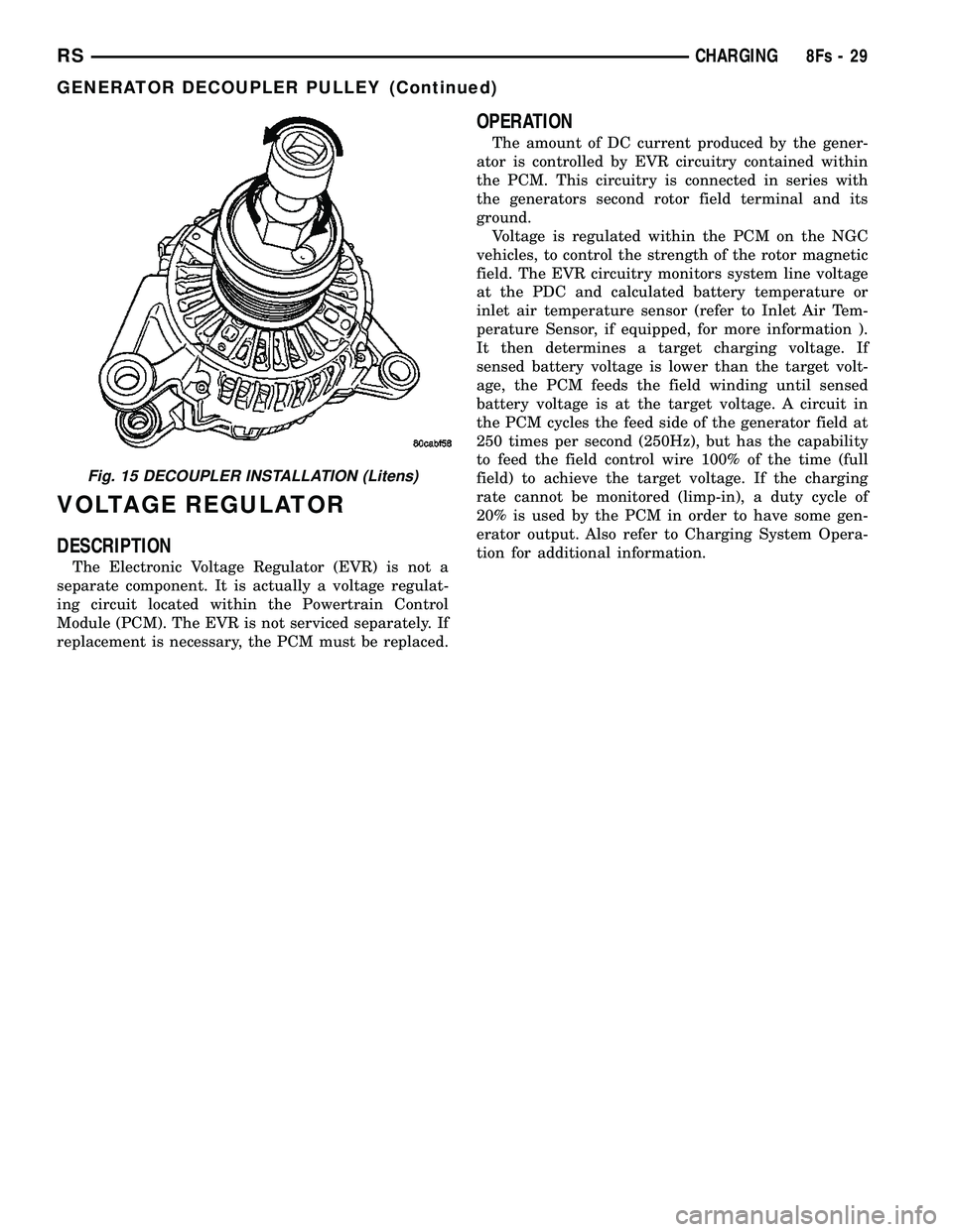
Fig. 15 DECOUPLER INSTALLATION (Litens)
RS CHARGING8Fs-29
GENERATOR DECOUPLER PULLEY (Continued)
Page 518 of 2585

FIRING ORDERAUTO SHUT DOWN RELAY
DESCRIPTION
The relay is located in the Power Distribution Cen-
ter (PDC). For the location of the relay within the
PDC, refer to the PDC cover for location. Check elec-
trical terminals for corrosion and repair as necessary
OPERATION
The engine switched battery (NGC vehicles)
informs the PCM when the ASD relay energizes. A 12
volt signal at this input indicates to the PCM that
the ASD has been activated. This input is also used
to power certain drivers on NGC vehicles.
When energized, the ASD relay on NGC vehicles
provides power to operate the injectors, ignition coil,
generator field, O2 sensor heaters (both upstream
and downstream), evaporative purge solenoid, EGR
solenoid (if equipped) wastegate solenoid (if
equipped), and NVLD solenoid (if equipped).
The ASD relay also provides a sense circuit to the
PCM for diagnostic purposes. If the PCM does not
receive 12 volts from this input after grounding the
control side of the ASD relay, it sets a Diagnostic
Trouble Code (DTC). The PCM energizes the ASD
any time there is an engine speed that exceeds a pre-
determined value (typically about 50 rpm). The ASD
relay can also be energized after the engine has been
turned off to perform an O2 sensor heater test, if
vehicle is equipped with OBD II diagnostics.
As mentioned earlier, the PCM energizes the ASD
relay during an O2 sensor heater test. On NGC vehi-
cles it checks the O2 heater upon vehicle start. The
PCM still operates internally to perform several
checks, including monitoring the O2 sensor heaters.
FIRING ORDER 2.4L
Firing Order 1-2-3-4-5-6 3.3/3.8L
1 - Electrical Connector
RSIGNITION CONTROL8I-3
IGNITION CONTROL (Continued)
Page 675 of 2585

NOTE: Turning the system off by depressing the
OFF switch or turning off the ignition switch will
erase the set speed stored in the PCM.
For added safety, the speed control system is pro-
grammed to disengage for any of the following condi-
tions:
²An indication of Park or Neutral
²A rapid increase rpm (indicates that the clutch
has been disengaged)
²Excessive engine rpm (indicates that the trans-
mission may be in a low gear)
²The speed signal increases at a rate of 10 mph
per second (indicates that the co-efficient of friction
between the road surface and tires is extremely low)
²The speed signal decreases at a rate of 10 mph
per second (indicates that the vehicle may have
decelerated at an extremely high rate)
²If the actual speed is greater than 20 mph over
the set speed.
²Autostick shifts into 1st or 2nd gear (autostick,
if equipped)
Once the speed control has been disengaged,
depressing the RESUME switch when speed is
greater than 20 mph allows the vehicle to resume
control to the target speed that was stored in the
PCM.
While the speed control is engaged, the driver can
increase the vehicle speed by depressing the ACCEL
switch. The new target speed is stored in the PCM
when the ACCEL switch is released. The PCM also
has a9tap-up9feature in which target speed
increases by 2 mph for each momentary switch acti-
vation of the ACCEL switch. The PCM also provides
a means to decelerate to a new lower target speed
without disengaging speed control. Depress and hold
the COAST switch until the desired speed is reached,
then release the switch.
The PCM also has a ªTap Downº feature in which
target speed decreases at 1 mph for each momentary
switch activation of the coast switch.
OPERATION - INTERACTIVE SPEED CONTROL
(4 Speed EATX Only)
Interactive means that communication between the
PCM and the TCM is taking place, this communica-
tion is internal to the PCM on NGC vehicles. Inter-
active speed control avoids unnecessary shifting for
smoother, quieter operation and when downshifts are
required, makes the shifts smoother.
CLIMBING A GRADE
DESCRIPTION
When climbing a grade the interactive speed con-
trol tries to maintain the set speed by increasing the
throttle opening, while inhibiting/delaying down-
shifts.
OPERATION
If opening the throttle alone cannot maintain the
set speed and the vehicle speed drops more than
three mph below the set speed, the transmission will
downshift to third gear. If the vehicle continues to
lose speed, by more than 6 mph, the transmission
will downshift again to maintain the set speed. After
the vehicle encounters a less-steep grade, or has
crested the grade (reduced the load on the power-
train) and can maintain the set speed at a reduced
throttle position, the transmission will upshift, as
appropriate, until the set speed can be maintained in
Overdrive.
GRADE HUNTING
DESCRIPTION
All vehicles equipped with a four speed automatic
transmission have a grade hunting feature for the
2nd to 3rd gear upshift and the 3rd to Overdrive
upshift.
OPERATION
The TCM (on SBEC vehicles) (PCM on NGC vehi-
cles) identifies the powertrain loading conditions and
selects the proper gear to maintain the current vehi-
cle speed. Under moderate loading conditions the
transaxle will stay in 3rd gear until the top of the
grade is reached or the powertrain loading is
reduced.
If powertrain loading is severe, the transaxle may
shift into 2nd gear and remain there until power-
train loading is reduced, then a 2nd to 3rd gear
upshift will be scheduled. Grade hunting features
always operate regardless of whether or not the
interactive speed control is engaged.If the interac-
tive speed control is not engaged and power-
train loading is not reduced, the driver may
have to completely lift off of the throttle before
an upshift will occur. If the driver does lift off the
throttle to induce an upshift under these conditions,
vehicle speed will reduce and the Overdrive to 3rd
and 3rd to 2nd gear downshifts will reoccur when the
throttle is reapplied. If grade hunting is repeatedly
induced by the driver, transaxle damage may result.
8P - 2 SPEED CONTROLRS
SPEED CONTROL (Continued)