warning CHRYSLER VOYAGER 2005 Service Manual
[x] Cancel search | Manufacturer: CHRYSLER, Model Year: 2005, Model line: VOYAGER, Model: CHRYSLER VOYAGER 2005Pages: 2339, PDF Size: 59.69 MB
Page 1376 of 2339
FUEL RAIL
REMOVAL
REMOVAL - 2.4L
(1) Perform fuel system pressure release procedure
before servicing or starting repairs.Refer to
Fuel System Pressure Release Procedure in this sec-
tion.
(2) Disconnect negative cable from battery.
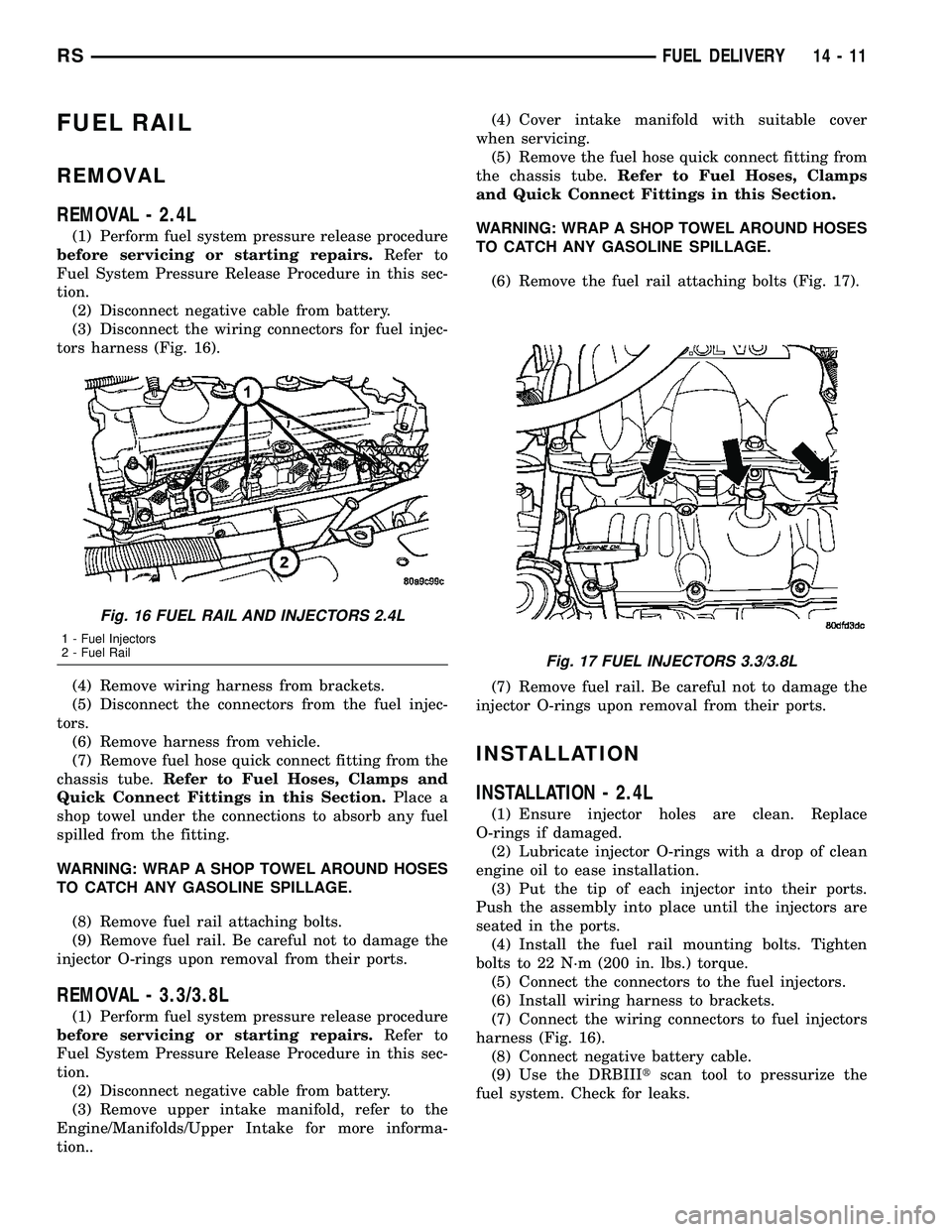
(3) Disconnect the wiring connectors for fuel injec-
tors harness (Fig. 16).
(4) Remove wiring harness from brackets.
(5) Disconnect the connectors from the fuel injec-
tors.
(6) Remove harness from vehicle.
(7) Remove fuel hose quick connect fitting from the
chassis tube.Refer to Fuel Hoses, Clamps and
Quick Connect Fittings in this Section.Place a
shop towel under the connections to absorb any fuel
spilled from the fitting.
WARNING: WRAP A SHOP TOWEL AROUND HOSES
TO CATCH ANY GASOLINE SPILLAGE.
(8) Remove fuel rail attaching bolts.
(9) Remove fuel rail. Be careful not to damage the
injector O-rings upon removal from their ports.
REMOVAL - 3.3/3.8L
(1) Perform fuel system pressure release procedure
before servicing or starting repairs.Refer to
Fuel System Pressure Release Procedure in this sec-
tion.
(2) Disconnect negative cable from battery.
(3) Remove upper intake manifold, refer to the
Engine/Manifolds/Upper Intake for more informa-
tion..(4) Cover intake manifold with suitable cover
when servicing.
(5) Remove the fuel hose quick connect fitting from
the chassis tube.Refer to Fuel Hoses, Clamps
and Quick Connect Fittings in this Section.
WARNING: WRAP A SHOP TOWEL AROUND HOSES
TO CATCH ANY GASOLINE SPILLAGE.
(6) Remove the fuel rail attaching bolts (Fig. 17).
(7) Remove fuel rail. Be careful not to damage the
injector O-rings upon removal from their ports.
INSTALLATION
INSTALLATION - 2.4L
(1) Ensure injector holes are clean. Replace
O-rings if damaged.
(2) Lubricate injector O-rings with a drop of clean
engine oil to ease installation.
(3) Put the tip of each injector into their ports.
Push the assembly into place until the injectors are
seated in the ports.
(4) Install the fuel rail mounting bolts. Tighten
bolts to 22 N´m (200 in. lbs.) torque.
(5) Connect the connectors to the fuel injectors.
(6) Install wiring harness to brackets.
(7) Connect the wiring connectors to fuel injectors
harness (Fig. 16).
(8) Connect negative battery cable.
(9) Use the DRBIIItscan tool to pressurize the
fuel system. Check for leaks.
Fig. 16 FUEL RAIL AND INJECTORS 2.4L
1 - Fuel Injectors
2 - Fuel Rail
Fig. 17 FUEL INJECTORS 3.3/3.8L
RSFUEL DELIVERY14-11
Page 1383 of 2339
QUICK CONNECT FITTING
STANDARD PROCEDURE - QUICK-CONNECT
FITTINGS
REMOVAL
When disconnecting a quick-connect fitting, the
retainer will remain on the fuel tube nipple.
WARNING: RELEASE FUEL SYSTEM PRESSURE
BEFORE DISCONNECTING A QUICK-CONNECT FIT-
TINGS. REFER TO THE FUEL PRESSURE RELEASE
PROCEDURE. THIS MAY RESULT IN PERSONAL
INJURY OR DEATH.
(1) Perform Fuel Pressure Release Procedure.
Refer to the Fuel Pressure Release Procedure in this
section.
(2) Disconnect negative cable from battery or aux-
iliary jumper terminal.
(3) Squeeze retainer tabs together and pull fuel
tube/quick-connect fitting assembly off of fuel tube
nipple. The retainer will remain on fuel tube.
INSTALLATION
CAUTION: Make sure that the o-ring in installed in
fitting. Never install a quick-connect fitting without
the retainer being either on the fuel tube or already
in the quick-connect fitting. In either case, ensure
the retainer locks securely into the quick-connect
fitting by firmly push-pulling-push on fuel tube and
fitting to ensure it is secured.
(1) Using a clean lint free cloth, clean the fuel tube
nipple and retainer.
(2) Prior to connecting the fitting to the fuel tube,
coat the fuel tube nipple with clean engine oil.
(3) Push the quick-connect fitting over the fuel
tube until theretainer seats and a click is heard.
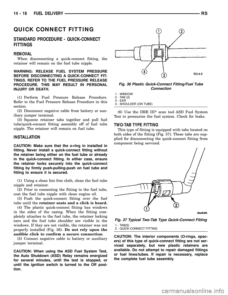
(4) The plastic quick-connect fitting has windows
in the sides of the casing. When the fitting com-
pletely attaches to the fuel tube, the retainer locking
ears and the fuel tube shoulder are visible in the
windows. If they are not visible, the retainer was not
properly installed (Fig. 36).Do not rely upon the
audible click to confirm a secure connection.
(5) Connect negative cable to battery or auxiliary
jumper terminal.
CAUTION: When using the ASD Fuel System Test,
the Auto Shutdown (ASD) Relay remains energized
for several minutes, until the test is stopped, or
until the ignition switch is turned to the Off posi-
tion.(6) Use the DRB IIItscan tool ASD Fuel System
Test to pressurize the fuel system. Check for leaks.
TWO-TAB TYPE FITTING
This type of fitting is equipped with tabs located on
both sides of the fitting (Fig. 37). These tabs are sup-
plied for disconnecting the quick-connect fitting from
component being serviced.
CAUTION: The interior components (O-rings, spac-
ers) of this type of quick-connect fitting are not ser-
viced separately, but new plastic retainers are
available. Do not attempt to repair damaged fittings
or fuel lines/tubes. If repair is necessary, replace
the complete fuel tube assembly.
Fig. 36 Plastic Quick-Connect Fitting/Fuel Tube
Connection
1 - WINDOW
2-TAB(2)
3 - EAR
4 - SHOULDER (ON TUBE)
Fig. 37 Typical Two-Tab Type Quick-Connect Fitting
1 - TAB(S)
2 - QUICK-CONNECT FITTING
14 - 18 FUEL DELIVERYRS
Page 1384 of 2339

WARNING: THE FUEL SYSTEM IS UNDER A CON-
STANT PRESSURE (EVEN WITH THE ENGINE OFF).
BEFORE SERVICING ANY FUEL SYSTEM HOSES,
FITTINGS OR LINES, THE FUEL SYSTEM PRES-
SURE MUST BE RELEASED. REFER TO THE FUEL
PRESSURE RELEASE PROCEDURE IN THIS
GROUP. THIS MAY RESULT IN PERSONAL INJURY
OR DEATH.
DISCONNECTION/CONNECTION
(1) Perform fuel pressure release procedure. Refer
to Fuel Pressure Release Procedure in this group.
(2) Disconnect negative battery cable from battery
or auxiliary jumper terminal.
(3) Clean fitting of any foreign material before dis-
assembly.
(4) To disconnect quick-connect fitting, squeeze
plastic retainer tabs (Fig. 37) against sides of quick-
connect fitting with your fingers. Tool use is not
required for removal and may damage plastic
retainer. Pull fitting from fuel system component
being serviced. The plastic retainer will remain on
component being serviced after fitting is discon-
nected. The O-rings and spacer will remain in quick-
connect fitting connector body.
(5) Inspect quick-connect fitting body and compo-
nent for damage. Replace as necessary.
CAUTION: When the quick-connect fitting was dis-
connected, the plastic retainer will remain on the
component being serviced. If this retainer must be
removed, very carefully release the retainer from
the component with two small screwdrivers. After
removal, inspect the retainer for cracks or any dam-
age.
(6) Prior to connecting quick-connect fitting to
component being serviced, check condition of fitting
and component. Clean parts with a lint-free cloth.
Lubricate with clean engine oil.
(7) Insert quick-connect fitting to component being
serviced and into plastic retainer. When a connection
is made, a click will be heard.
(8) Verify a locked condition by firmly push-pull-
ing-push on fuel tube and fitting (15-30 lbs.).
(9) Connect negative cable to battery or auxiliary
jumper terminal.
(10) Use the DRB IIItscan tool ASD Fuel System
Test to pressurize the fuel system. Check for leaks.PLASTIC RETAINER RING TYPE FITTING
This type of fitting can be identified by the use of a
full-round plastic retainer ring (Fig. 38) usually black
in color.
CAUTION: The interior components (O-rings, spac-
ers, retainers) of this type of quick-connect fitting
are not serviced separately. Do not attempt to repair
damaged fittings or fuel lines/tubes. If repair is nec-
essary, replace the complete fuel tube assembly.
WARNING: THE FUEL SYSTEM IS UNDER A CON-
STANT PRESSURE (EVEN WITH THE ENGINE OFF).
BEFORE SERVICING ANY FUEL SYSTEM HOSES,
FITTINGS OR LINES, THE FUEL SYSTEM PRES-
SURE MUST BE RELEASED. REFER TO THE FUEL
SYSTEM PRESSURE RELEASE PROCEDURE IN
THIS GROUP. THIS MAY RESULT IN PERSONAL
INJURY OR DEATH.
Fig. 38 Plastic Retainer Ring Type Fitting
1 - FUEL TUBE
2 - QUICK CONNECT FITTING
3 - PUSH
4 - PLASTIC RETAINER
5 - PUSH
6 - PUSH
7 - PUSH
8 - PUSH
RSFUEL DELIVERY14-19
QUICK CONNECT FITTING (Continued)
Page 1417 of 2339
COLUMN
TABLE OF CONTENTS
page page
COLUMN
DESCRIPTION - STEERING COLUMN.......10
WARNING
WARNINGS AND CAUTIONS.............10
DIAGNOSIS AND TESTING - STEERING
COLUMN............................11
REMOVAL.............................11
INSTALLATION.........................16
SPECIFICATIONS
COLUMN FASTENER TORQUE...........17
IGNITION SWITCH
REMOVAL.............................17
INSTALLATION.........................19
KEY/LOCK CYLINDER
DESCRIPTION.........................20OPERATION...........................20
REMOVAL.............................20
INSTALLATION.........................20
SHROUD - LOWER
REMOVAL.............................21
INSTALLATION.........................21
SHROUD - UPPER
REMOVAL.............................22
INSTALLATION.........................22
STEERING WHEEL
REMOVAL.............................23
INSTALLATION.........................24
COLUMN
DESCRIPTION - STEERING COLUMN
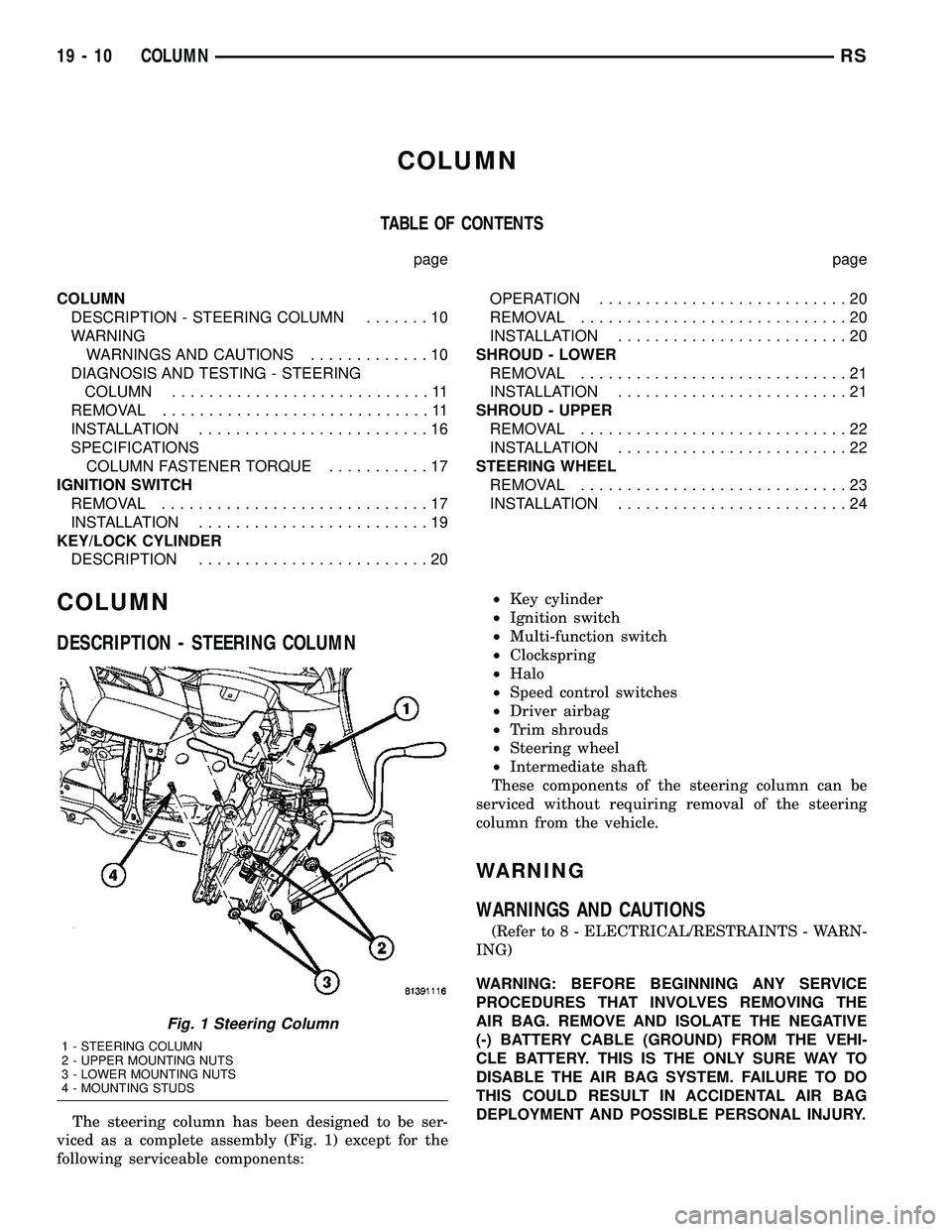
The steering column has been designed to be ser-
viced as a complete assembly (Fig. 1) except for the
following serviceable components:²Key cylinder
²Ignition switch
²Multi-function switch
²Clockspring
²Halo
²Speed control switches
²Driver airbag
²Trim shrouds
²Steering wheel
²Intermediate shaft
These components of the steering column can be
serviced without requiring removal of the steering
column from the vehicle.
WARNING
WARNINGS AND CAUTIONS
(Refer to 8 - ELECTRICAL/RESTRAINTS - WARN-
ING)
WARNING: BEFORE BEGINNING ANY SERVICE
PROCEDURES THAT INVOLVES REMOVING THE
AIR BAG. REMOVE AND ISOLATE THE NEGATIVE
(-) BATTERY CABLE (GROUND) FROM THE VEHI-
CLE BATTERY. THIS IS THE ONLY SURE WAY TO
DISABLE THE AIR BAG SYSTEM. FAILURE TO DO
THIS COULD RESULT IN ACCIDENTAL AIR BAG
DEPLOYMENT AND POSSIBLE PERSONAL INJURY.
Fig. 1 Steering Column
1 - STEERING COLUMN
2 - UPPER MOUNTING NUTS
3 - LOWER MOUNTING NUTS
4 - MOUNTING STUDS
19 - 10 COLUMNRS
Page 1418 of 2339
WARNING: THE AIR BAG SYSTEM IS A SENSITIVE,
COMPLEX ELECTRO-MECHANICAL UNIT. BEFORE
ATTEMPTING TO DIAGNOSE, REMOVE OR INSTALL
THE AIR BAG SYSTEM COMPONENTS YOU MUST
FIRST DISCONNECT AND ISOLATE THE BATTERY
NEGATIVE (GROUND) CABLE. THEN WAIT TWO
MINUTES FOR THE SYSTEM CAPACITOR TO DIS-
CHARGE. FAILURE TO DO SO COULD RESULT IN
ACCIDENTAL DEPLOYMENT OF THE AIR BAG AND
POSSIBLE PERSONAL INJURY. THE FASTENERS,
SCREWS, AND BOLTS, ORIGINALLY USED FOR
THE AIR BAG COMPONENTS, HAVE SPECIAL
COATINGS AND ARE SPECIFICALLY DESIGNED
FOR THE AIR BAG SYSTEM. THEY MUST NEVER
BE REPLACED WITH ANY SUBSTITUTES. ANYTIME
A NEW FASTENER IS NEEDED, REPLACE WITH
THE CORRECT FASTENERS PROVIDED IN THE
SERVICE PACKAGE OR FASTENERS LISTED IN
THE PARTS BOOKS.
WARNING: SAFETY GOGGLES SHOULD BE WORN
AT ALL TIMES WHEN WORKING ON STEERING
COLUMNS.
CAUTION: Disconnect negative (ground) cable from
the battery before servicing any column compo-
nent.
CAUTION: Do not attempt to remove the pivot pins
to disassemble the tilting mechanism. Damage will
occur.
DIAGNOSIS AND TESTING - STEERING
COLUMN
For diagnosis of conditions relating to the steering
column, (Refer to 19 - STEERING - DIAGNOSIS
AND TESTING).
REMOVAL
NOTE: Before proceeding, (Refer to 19 - STEERING/
COLUMN - WARNING)(Refer to 8 - ELECTRICAL/RE-
STRAINTS/DRIVER AIRBAG - REMOVAL).
(1) Make sure the front wheels of the vehicle are
in the STRAIGHT AHEAD position before beginning
the column removal procedure.
(2) Disconnect and isolate the negative (ground)
cable from the battery. Wait at least two minutes for
the airbag system reserve capacitor to discharge
before beginning any steering column, instrument
panel, or airbag system/component service.WARNING: WHEN AN UNDEPLOYED AIRBAG IS TO
BE REMOVED FROM THE VEHICLE, FIRST DISCON-
NECT AND ISOLATE THE BATTERY NEGATIVE
(GROUND) CABLE. ALLOW THE AIRBAG SYSTEM
RESERVE CAPACITOR TO DISCHARGE FOR TWO
MINUTES BEFORE BEGINNING ANY AIRBAG SYS-
TEM OR COMPONENT SERVICE. PERSONAL
INJURY MAY RESULT IF THIS PROCEDURE IS NOT
FOLLOWED.
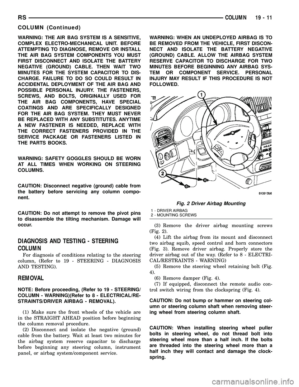
(3) Remove the driver airbag mounting screws
(Fig. 2).
(4) Lift the airbag from its mount and disconnect
two airbag squib, speed control and horn connectors
(Fig. 3). Remove driver airbag. Properly store the
driver airbag out of the way. (Refer to 8 - ELECTRI-
CAL/RESTRAINTS - WARNING)
(5) Remove the steering wheel retaining bolt (Fig.
4).
(6) Remove damper (Fig. 4).
(7) If equipped, disconnect the remote audio con-
trol switch wiring from the clockspring (Fig. 4).
CAUTION: Do not bump or hammer on steering col-
umn or steering column shaft when removing steer-
ing wheel from steering column shaft.
CAUTION: When installing steering wheel puller
bolts in steering wheel, do not thread bolt into
steering wheel more than a half inch. If the bolts
are threaded into the steering wheel more than a
half inch they will contact and damage the clock-
spring.
Fig. 2 Driver Airbag Mounting
1 - DRIVER AIRBAG
2 - MOUNTING SCREWS
RSCOLUMN19-11
COLUMN (Continued)
Page 1423 of 2339
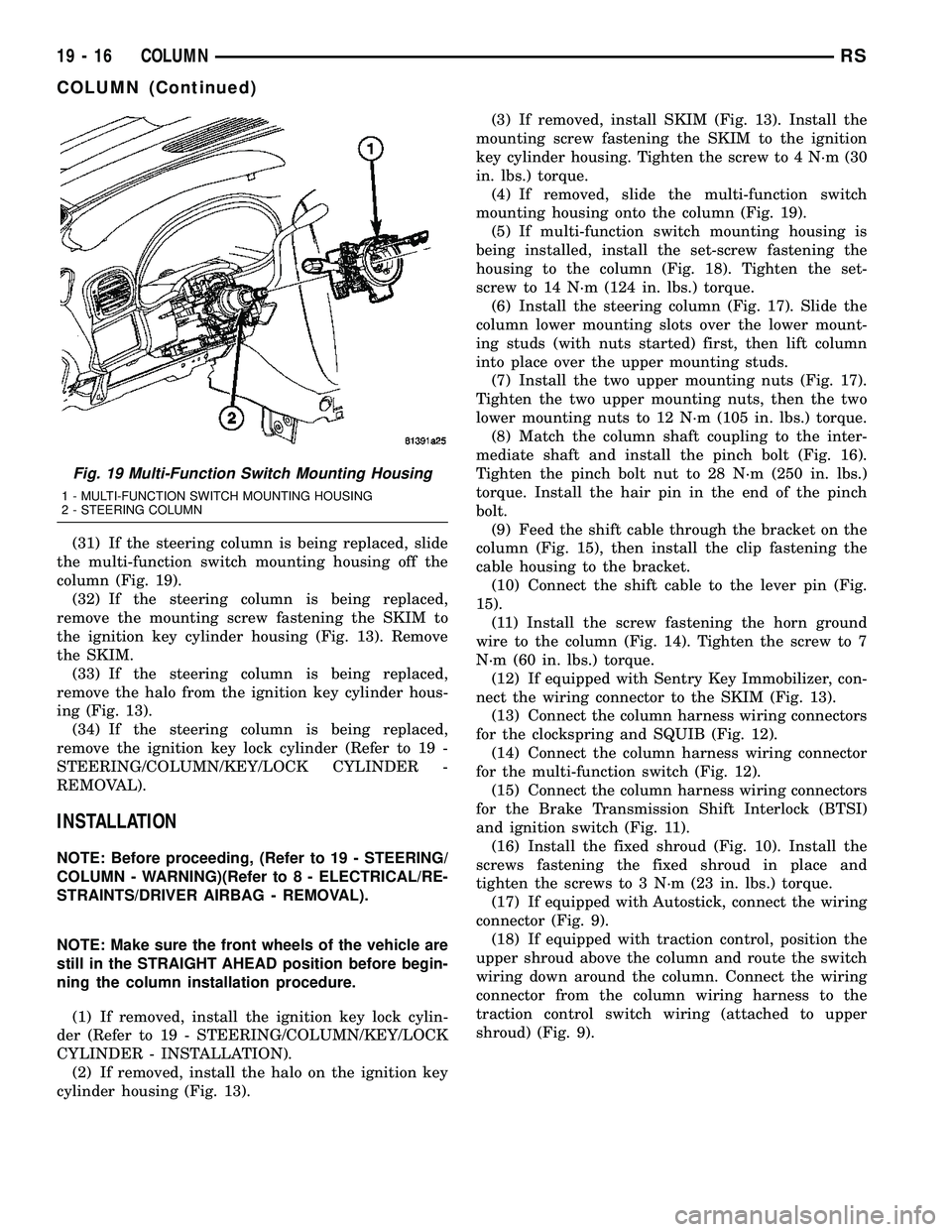
(31) If the steering column is being replaced, slide
the multi-function switch mounting housing off the
column (Fig. 19).
(32) If the steering column is being replaced,
remove the mounting screw fastening the SKIM to
the ignition key cylinder housing (Fig. 13). Remove
the SKIM.
(33) If the steering column is being replaced,
remove the halo from the ignition key cylinder hous-
ing (Fig. 13).
(34) If the steering column is being replaced,
remove the ignition key lock cylinder (Refer to 19 -
STEERING/COLUMN/KEY/LOCK CYLINDER -
REMOVAL).
INSTALLATION
NOTE: Before proceeding, (Refer to 19 - STEERING/
COLUMN - WARNING)(Refer to 8 - ELECTRICAL/RE-
STRAINTS/DRIVER AIRBAG - REMOVAL).
NOTE: Make sure the front wheels of the vehicle are
still in the STRAIGHT AHEAD position before begin-
ning the column installation procedure.
(1) If removed, install the ignition key lock cylin-
der (Refer to 19 - STEERING/COLUMN/KEY/LOCK
CYLINDER - INSTALLATION).
(2) If removed, install the halo on the ignition key
cylinder housing (Fig. 13).(3) If removed, install SKIM (Fig. 13). Install the
mounting screw fastening the SKIM to the ignition
key cylinder housing. Tighten the screw to 4 N´m (30
in. lbs.) torque.
(4) If removed, slide the multi-function switch
mounting housing onto the column (Fig. 19).
(5) If multi-function switch mounting housing is
being installed, install the set-screw fastening the
housing to the column (Fig. 18). Tighten the set-
screw to 14 N´m (124 in. lbs.) torque.
(6) Install the steering column (Fig. 17). Slide the
column lower mounting slots over the lower mount-
ing studs (with nuts started) first, then lift column
into place over the upper mounting studs.
(7) Install the two upper mounting nuts (Fig. 17).
Tighten the two upper mounting nuts, then the two
lower mounting nuts to 12 N´m (105 in. lbs.) torque.
(8) Match the column shaft coupling to the inter-
mediate shaft and install the pinch bolt (Fig. 16).
Tighten the pinch bolt nut to 28 N´m (250 in. lbs.)
torque. Install the hair pin in the end of the pinch
bolt.
(9) Feed the shift cable through the bracket on the
column (Fig. 15), then install the clip fastening the
cable housing to the bracket.
(10) Connect the shift cable to the lever pin (Fig.
15).
(11) Install the screw fastening the horn ground
wire to the column (Fig. 14). Tighten the screw to 7
N´m (60 in. lbs.) torque.
(12) If equipped with Sentry Key Immobilizer, con-
nect the wiring connector to the SKIM (Fig. 13).
(13) Connect the column harness wiring connectors
for the clockspring and SQUIB (Fig. 12).
(14) Connect the column harness wiring connector
for the multi-function switch (Fig. 12).
(15) Connect the column harness wiring connectors
for the Brake Transmission Shift Interlock (BTSI)
and ignition switch (Fig. 11).
(16) Install the fixed shroud (Fig. 10). Install the
screws fastening the fixed shroud in place and
tighten the screws to 3 N´m (23 in. lbs.) torque.
(17) If equipped with Autostick, connect the wiring
connector (Fig. 9).
(18) If equipped with traction control, position the
upper shroud above the column and route the switch
wiring down around the column. Connect the wiring
connector from the column wiring harness to the
traction control switch wiring (attached to upper
shroud) (Fig. 9).
Fig. 19 Multi-Function Switch Mounting Housing
1 - MULTI-FUNCTION SWITCH MOUNTING HOUSING
2 - STEERING COLUMN
19 - 16 COLUMNRS
COLUMN (Continued)
Page 1427 of 2339

(6) Connect negative cable to battery.
(7) Check for proper operation of ignition switch
and key-in warning switch.
KEY/LOCK CYLINDER
DESCRIPTION
The lock cylinder is inserted in the end of the
housing opposite the ignition switch.
OPERATION
The ignition key rotates the cylinder to 5 different
detents (Fig. 30) :
²Accessory
²Off (lock)
²Unlock
²On/Run
²Start
REMOVAL
(1) Disconnect negative cable from battery.
(2) Remove steering column cover retaining
screws.
(3) Remove screws holding steering column
shrouds and remove lower shroud.
(4) Place key cylinder in RUN position. Depress
lock cylinder retaining tab on the bottom of the lock
housing and remove key cylinder.
INSTALLATION
(1) Install key in lock cylinder. Turn key to run
position (retaining tab on lock cylinder can be
depressed).(2) The shaft at the end of the lock cylinder aligns
with the socket in the end of the housing. To align
the socket with the lock cylinder, ensure the socket is
in the Run position (Fig. 31).
(3) Align the lock cylinder with the grooves in the
housing. Slide the lock cylinder into the housing
until the tab sticks through the opening in the hous-
ing.
(4) Turn the key to the Off position. Remove the
key.
(5) Install lower steering column shroud.
(6) Install steering column cover.
(7) Connect negative cable to battery.
Fig. 29 Ignition Switch Installation
1 - IGNITION SWITCH
2 - ACTUATOR SHAFT
3 - RETAINING TABS
Fig. 30 Ignition Lock Cylinder Detents
Fig. 31 Socket in Lock Cylinder Housing
1 - LOCK CYLINDER HOUSING
2 - SOCKET
19 - 20 COLUMNRS
IGNITION SWITCH (Continued)
Page 1430 of 2339
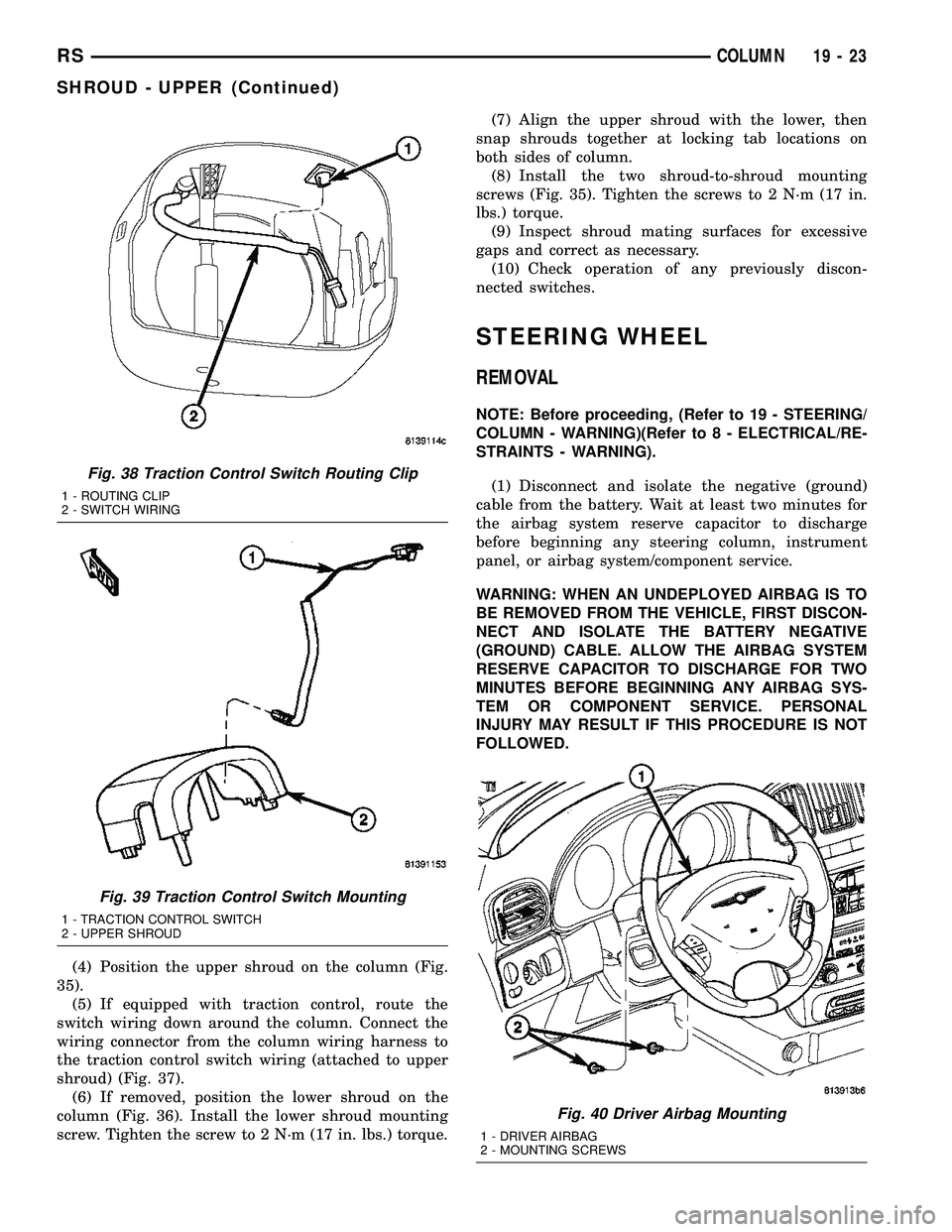
(4) Position the upper shroud on the column (Fig.
35).
(5) If equipped with traction control, route the
switch wiring down around the column. Connect the
wiring connector from the column wiring harness to
the traction control switch wiring (attached to upper
shroud) (Fig. 37).
(6) If removed, position the lower shroud on the
column (Fig. 36). Install the lower shroud mounting
screw. Tighten the screw to 2 N´m (17 in. lbs.) torque.(7) Align the upper shroud with the lower, then
snap shrouds together at locking tab locations on
both sides of column.
(8) Install the two shroud-to-shroud mounting
screws (Fig. 35). Tighten the screws to 2 N´m (17 in.
lbs.) torque.
(9) Inspect shroud mating surfaces for excessive
gaps and correct as necessary.
(10) Check operation of any previously discon-
nected switches.
STEERING WHEEL
REMOVAL
NOTE: Before proceeding, (Refer to 19 - STEERING/
COLUMN - WARNING)(Refer to 8 - ELECTRICAL/RE-
STRAINTS - WARNING).
(1) Disconnect and isolate the negative (ground)
cable from the battery. Wait at least two minutes for
the airbag system reserve capacitor to discharge
before beginning any steering column, instrument
panel, or airbag system/component service.
WARNING: WHEN AN UNDEPLOYED AIRBAG IS TO
BE REMOVED FROM THE VEHICLE, FIRST DISCON-
NECT AND ISOLATE THE BATTERY NEGATIVE
(GROUND) CABLE. ALLOW THE AIRBAG SYSTEM
RESERVE CAPACITOR TO DISCHARGE FOR TWO
MINUTES BEFORE BEGINNING ANY AIRBAG SYS-
TEM OR COMPONENT SERVICE. PERSONAL
INJURY MAY RESULT IF THIS PROCEDURE IS NOT
FOLLOWED.
Fig. 38 Traction Control Switch Routing Clip
1 - ROUTING CLIP
2 - SWITCH WIRING
Fig. 39 Traction Control Switch Mounting
1 - TRACTION CONTROL SWITCH
2 - UPPER SHROUD
Fig. 40 Driver Airbag Mounting
1 - DRIVER AIRBAG
2 - MOUNTING SCREWS
RSCOLUMN19-23
SHROUD - UPPER (Continued)
Page 1431 of 2339

(2) Remove the driver airbag mounting screws
(Fig. 40).
(3) Lift the airbag from its mount and disconnect
two airbag squib, speed control and horn connectors
(Fig. 41). Remove driver airbag. Properly store the
driver airbag out of the way. (Refer to 8 - ELECTRI-
CAL/RESTRAINTS - WARNING)(4) Remove the steering wheel retaining bolt (Fig.
42).
(5) Remove damper (Fig. 42).
(6) If equipped, disconnect the remote audio con-
trol switch wiring from the clockspring (Fig. 42).
CAUTION: Do not bump or hammer on steering col-
umn or steering column shaft when removing steer-
ing wheel from steering column shaft.
CAUTION: When installing steering wheel puller
bolts in steering wheel, do not thread bolt into
steering wheel more than a half inch. If the bolts
are threaded into the steering wheel more than a
half inch they will contact and damage the clock-
spring.
(7) While holding the steering wheel firmly in the
straight-aheadposition, remove the steering wheel
from steering column shaft using a steering wheel
puller (Fig. 43).
(8) Remove the puller from the steering wheel.
(9) If the remote audio switches need removed
from the steering wheel, (Refer to 8 - ELECTRICAL/
AUDIO/REMOTE SWITCHES - REMOVAL).
INSTALLATION
(1) If the remote radio switches need to be
installed on the steering wheel, (Refer to 8 - ELEC-
TRICAL/AUDIO/REMOTE SWITCHES - INSTALLA-
TION).
CAUTION: Do not force steering wheel onto steer-
ing column shaft by driving it on. Pull steering
wheel down onto shaft using only the steering
wheel retaining nut.
Fig. 41 Driver Airbag Wiring Connections
1 - DRIVER AIRBAG
2 - SQUIB CONNECTORS
3 - SPEED CONTROL/HORN WIRING CONNECTOR
4 - CLOCKSPRING
Fig. 42 Steering Wheel Mounting
1 - STEERING WHEEL
2 - REMOTE AUDIO CONTROL WIRING CONNECTOR (IF
EQUIPPED)
3 - RETAINING BOLT
4 - DAMPER
Fig. 43 Steering Wheel Removal
1 - STEERING WHEEL
2 - PULLER
19 - 24 COLUMNRS
STEERING WHEEL (Continued)
Page 1433 of 2339

GEAR
TABLE OF CONTENTS
page page
GEAR
DESCRIPTION.........................26
OPERATION...........................26
WARNING
WARNINGS AND CAUTIONS.............26
REMOVAL
REMOVAL - LHD GEAR.................26
REMOVAL - RHD GEAR................29INSTALLATION
INSTALLATION - LHD GEAR.............31
INSTALLATION - RHD GEAR.............33
SPECIAL TOOLS
POWER STEERING GEAR..............34
OUTER TIE ROD
REMOVAL.............................34
INSTALLATION.........................35
GEAR
DESCRIPTION
This vehicle is equipped with a rack and pinion
power steering gear (Fig. 1). It is mounted to the
underside of the front suspension cradle/crossmem-
ber.
The steering column is attached to the gear
through the use of an intermediate shaft and cou-
plers. The outer ends of the power steering gear's
outer tie rods connect to the steering knuckles.
NOTE: The power steering gear should NOT be ser-
viced or adjusted unless DaimlerChrysler Corpora-
tion authorizes. If a malfunction or oil leak occurs,
the complete steering gear should be replaced.
Only the outer tie rods may be replaced separately
from the rest of the gear.
OPERATION
Turning of the steering wheel is converted into lin-
ear (side-to-side) travel through the meshing of the
helical pinion teeth with the rack teeth in the steer-
ing gear. This travel pushes and pulls the tie rods to
change the direction of the vehicle's front wheels.
Power assist steering provided by the power steer-
ing pump is controlled by an open center, rotary type
control valve which directs oil from the pump to
either side of the integral rack piston upon demand.
Road feel is controlled by the diameter of a torsion
bar which initially steers the vehicle. As required
steering effort increases, as in a turn, the torsion bar
twists, causing relative rotary motion between the
rotary valve body and the valve spool. This move-
ment directs oil behind the integral rack piston
which, in turn, builds hydraulic pressure and assists
in the turning effort.Manual steering control of the vehicle can be main-
tained if power steering assist is lost. However,
under this condition, steering effort is significantly
increased.
WARNING
WARNINGS AND CAUTIONS
WARNING: POWER STEERING FLUID, ENGINE
PARTS AND EXHAUST SYSTEM MAY BE
EXTREMELY HOT IF ENGINE HAS BEEN RUNNING.
DO NOT START ENGINE WITH ANY LOOSE OR DIS-
CONNECTED HOSES. DO NOT ALLOW HOSES TO
TOUCH HOT EXHAUST MANIFOLD OR CATALYST.
WARNING: FLUID LEVEL SHOULD BE CHECKED
WITH THE ENGINE OFF TO PREVENT PERSONAL
INJURY FROM MOVING PARTS.
CAUTION: When the system is open, cap all open
ends of the hoses, power steering pump fittings or
power steering gear ports to prevent entry of for-
eign material into the components.
REMOVAL
REMOVAL - LHD GEAR
(1) Remove cap from power steering fluid reser-
voir.
(2) Using a siphon pump, remove as much fluid as
possible from the power steering fluid reservoir.Use
care not to damage the filter mesh below the
fluid surface.
19 - 26 GEARRS