air filter CHRYSLER VOYAGER 2005 User Guide
[x] Cancel search | Manufacturer: CHRYSLER, Model Year: 2005, Model line: VOYAGER, Model: CHRYSLER VOYAGER 2005Pages: 2339, PDF Size: 59.69 MB
Page 31 of 2339
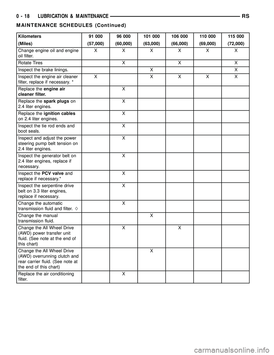
Kilometers 91 000 96 000 101 000 106 000 110 000 115 000
(Miles) (57,000) (60,000) (63,000) (66,000) (69,000) (72,000)
Change engine oil and engine
oil filter.XXXXX X
Rotate Tires X X X
Inspect the brake linings. X X
Inspect the engine air cleaner
filter, replace if necessary. *X XXX X
Replace theengine air
cleaner filter.X
Replace thespark plugson
2.4 liter engines.X
Replace theignition cables
on 2.4 liter engines.X
Inspect the tie rod ends and
boot seals.X
Inspect and adjust the power
steering pump belt tension on
2.4 liter engines.X
Inspect the generator belt on
2.4 liter engines, replace if
necessary.X
Inspect thePCV valveand
replace if necessary.*X
Inspect the serpentine drive
belt on 3.3 liter engines,
replace if necessary.X
Change the automatic
transmission fluid and filter.LX
Change the manual
transmission fluid.X
Change the All Wheel Drive
(AWD) power transfer unit
fluid. (See note at the end of
this chart)XX
Change the All Wheel Drive
(AWD) overrunning clutch and
rear carrier fluid. (See note at
the end of this chart)X
Replace the air conditioning
filter.X
0 - 18 LUBRICATION & MAINTENANCERS
MAINTENANCE SCHEDULES (Continued)
Page 32 of 2339
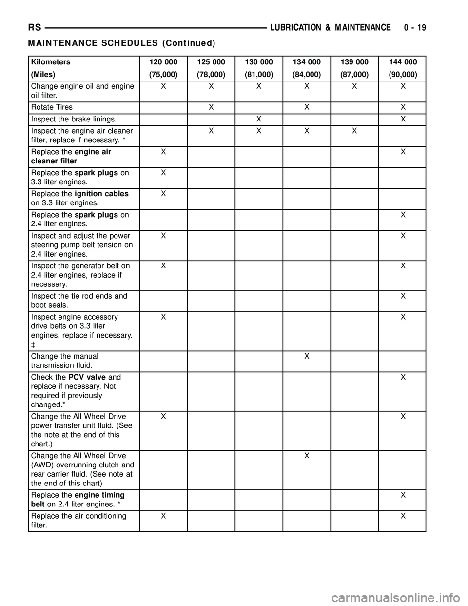
Kilometers 120 000 125 000 130 000 134 000 139 000 144 000
(Miles) (75,000) (78,000) (81,000) (84,000) (87,000) (90,000)
Change engine oil and engine
oil filter.XXXXX X
Rotate Tires X X X
Inspect the brake linings. X X
Inspect the engine air cleaner
filter, replace if necessary. *XXXX
Replace theengine air
cleaner filterXX
Replace thespark plugson
3.3 liter engines.X
Replace theignition cables
on 3.3 liter engines.X
Replace thespark plugson
2.4 liter engines.X
Inspect and adjust the power
steering pump belt tension on
2.4 liter engines.XX
Inspect the generator belt on
2.4 liter engines, replace if
necessary.XX
Inspect the tie rod ends and
boot seals.X
Inspect engine accessory
drive belts on 3.3 liter
engines, replace if necessary.
³XX
Change the manual
transmission fluid.X
Check thePCV valveand
replace if necessary. Not
required if previously
changed.*X
Change the All Wheel Drive
power transfer unit fluid. (See
the note at the end of this
chart.)XX
Change the All Wheel Drive
(AWD) overrunning clutch and
rear carrier fluid. (See note at
the end of this chart)X
Replace theengine timing
belton 2.4 liter engines. *X
Replace the air conditioning
filter.XX
RSLUBRICATION & MAINTENANCE0-19
MAINTENANCE SCHEDULES (Continued)
Page 33 of 2339
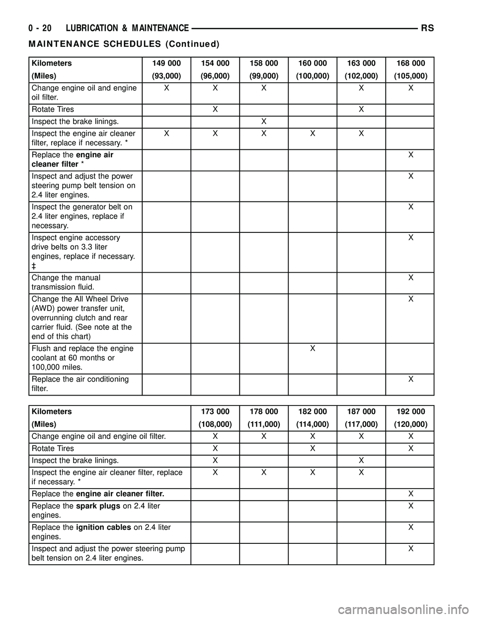
Kilometers 149 000 154 000 158 000 160 000 163 000 168 000
(Miles) (93,000) (96,000) (99,000) (100,000) (102,000) (105,000)
Change engine oil and engine
oil filter.XXX X X
Rotate Tires X X
Inspect the brake linings. X
Inspect the engine air cleaner
filter, replace if necessary. *XXXXX
Replace theengine air
cleaner filter*X
Inspect and adjust the power
steering pump belt tension on
2.4 liter engines.X
Inspect the generator belt on
2.4 liter engines, replace if
necessary.X
Inspect engine accessory
drive belts on 3.3 liter
engines, replace if necessary.
³X
Change the manual
transmission fluid.X
Change the All Wheel Drive
(AWD) power transfer unit,
overrunning clutch and rear
carrier fluid. (See note at the
end of this chart)X
Flush and replace the engine
coolant at 60 months or
100,000 miles.X
Replace the air conditioning
filter.X
Kilometers 173 000 178 000 182 000 187 000 192 000
(Miles) (108,000) (111,000) (114,000) (117,000) (120,000)
Change engine oil and engine oil filter.XXXX X
Rotate Tires X X X
Inspect the brake linings. X X
Inspect the engine air cleaner filter, replace
if necessary. *XXXX
Replace theengine air cleaner filter.X
Replace thespark plugson 2.4 liter
engines.X
Replace theignition cableson 2.4 liter
engines.X
Inspect and adjust the power steering pump
belt tension on 2.4 liter engines.X
0 - 20 LUBRICATION & MAINTENANCERS
MAINTENANCE SCHEDULES (Continued)
Page 34 of 2339
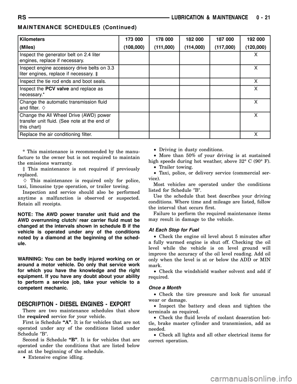
Kilometers 173 000 178 000 182 000 187 000 192 000
(Miles) (108,000) (111,000) (114,000) (117,000) (120,000)
Inspect the generator belt on 2.4 liter
engines, replace if necessary.X
Inspect engine accessory drive belts on 3.3
liter engines, replace if necessary. ³X
Inspect the tie rod ends and boot seals. X
Inspect thePCV valveand replace as
necessary.*X
Change the automatic transmission fluid
and filter.LX
Change the All Wheel Drive (AWD) power
transfer unit fluid. (See note at the end of
this chart)X
Replace the air conditioning filter.X
* This maintenance is recommended by the manu-
facture to the owner but is not required to maintain
the emissions warranty.
³ This maintenance is not required if previously
replaced.
LThis maintenance is required only for police,
taxi, limousine type operation, or trailer towing.
Inspection and service should also be performed
anytime a malfunction is observed or suspected.
Retain all receipts.
NOTE: The AWD power transfer unit fluid and the
AWD overrunning clutch/ rear carrier fluid must be
changed at the intervals shown in schedule B if the
vehicle is operated under any of the conditions
noted by a diamond at the beginning of the sched-
ule.
WARNING: You can be badly injured working on or
around a motor vehicle. Do only that service work
for which you have the knowledge and the right
equipment. If you have any doubt about your ability
to perform a service job, take your vehicle to a
competent mechanic.
DESCRIPTION - DIESEL ENGINES - EXPORT
There are two maintenance schedules that show
therequiredservice for your vehicle.
First is ScheduleªAº. It is for vehicles that are not
operated under any of the conditions listed under
Schedule9B9.
Second is ScheduleªBº. It is for vehicles that are
operated under the conditions that are listed below
and at the beginning of the schedule.
²Extensive engine idling.²Driving in dusty conditions.
²More than 50% of your driving is at sustained
high speeds during hot weather, above 32É C (90É F).
²Trailer towing.
²Taxi, police, or delivery service (commercial ser-
vice).
Most vehicles are operated under the conditions
listed for Schedule9B9.
Use the schedule that best describes your driving
conditions. Where time and mileage are listed, follow
the interval that occurs first.
Failure to perform the required maintenance items
may result in damage to the vehicle.
At Each Stop for Fuel
²Check the engine oil level about 5 minutes after
a fully warmed engine is shut off. Checking the oil
level while the vehicle is on level ground will
improve the accuracy of the oil level reading. Add oil
only when the level is at or below the ADD or MIN
mark.
²Check the windshield washer solvent and add if
required.
Once a Month
²Check the tire pressure and look for unusual
wear or damage.
²Inspect the battery and clean and tighten the
terminals as required.
²Check the fluid levels of coolant deaeration bot-
tle, brake master cylinder and transmission, add as
needed.
²Check all lights and all other electrical items for
correct operation.
RSLUBRICATION & MAINTENANCE0-21
MAINTENANCE SCHEDULES (Continued)
Page 35 of 2339
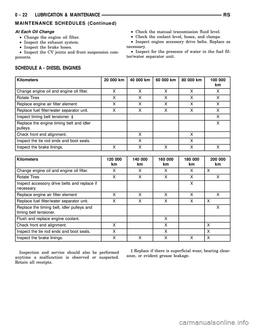
At Each Oil Change
²Change the engine oil filter.
²Inspect the exhaust system.
²Inspect the brake hoses.
²Inspect the CV joints and front suspension com-
ponents.²Check the manual transmission fluid level.
²Check the coolant level, hoses, and clamps.
²Inspect engine accessory drive belts. Replace as
necessary.
²Inspect for the presence of water in the fuel fil-
ter/water separator unit.
SCHEDULE A - DIESEL ENGINES
Kilometers 20 000 km 40 000 km 60 000 km 80 000 km 100 000
km
Change engine oil and engine oil filter.XXXX X
Rotate TiresXXXX X
Replace engine air filter elementXXXX X
Replace fuel filter/water separator unit.XXXX X
Inspect timing belt tensioner. ³X
Replace the engine timing belt and idler
pulleys.X
Check front end alignment. X X
Inspect the tie rod ends and boot seals. X X
Inspect the brake linings.XXXX X
Kilometers 120 000
km140 000
km160 000
km180 000
km200 000
km
Change engine oil and engine oil filter.XXXXX
Rotate TiresXXXX X
Inspect accessory drive belts and replace if
necessary.X
Replace engine air filter elementXXXX X
Replace fuel filter/water separator unit.XXXXX
Replace the timing belt, idler pulleys and
timing belt tensioner.X
Flush and replace engine coolant. X
Check front end alignment. X X X
Inspect the tie rod ends and boot seals. X X X
Inspect the brake linings.XXXXX
Inspection and service should also be performed
anytime a malfunction is observed or suspected.
Retain all receipts.³ Replace if there is superficial wear, bearing clear-
ance, or evident grease leakage.
0 - 22 LUBRICATION & MAINTENANCERS
MAINTENANCE SCHEDULES (Continued)
Page 36 of 2339
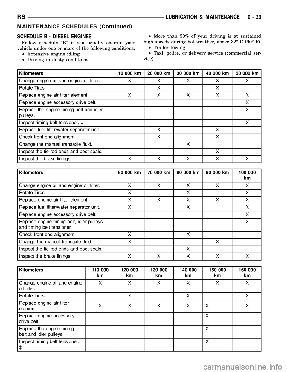
SCHEDULE B - DIESEL ENGINES
Follow schedule ªBº if you usually operate your
vehicle under one or more of the following conditions.
²Extensive engine idling.
²Driving in dusty conditions.²More than 50% of your driving is at sustained
high speeds during hot weather, above 32É C (90É F).
²Trailer towing.
²Taxi, police, or delivery service (commercial ser-
vice).
Kilometers 10 000 km 20 000 km 30 000 km 40 000 km 50 000 km
Change engine oil and engine oil filter.XXXX X
Rotate Tires X X
Replace engine air filter elementXXXX X
Replace engine accessory drive belt. X
Replace the engine timing belt and idler
pulleys.X
Inspect timing belt tensioner. ³X
Replace fuel filter/water separator unit. X X
Check front end alignment. X X
Change the manual transaxle fluid. X
Inspect the tie rod ends and boot seals. X
Inspect the brake linings.XXXX X
Kilometers 60 000 km 70 000 km 80 000 km 90 000 km 100 000
km
Change engine oil and engine oil filter.XXXX X
Rotate Tires X X X
Replace engine air filter elementXXXX X
Replace fuel filter/water separator unit. X X X
Replace engine accessory drive belt. X
Replace engine timing belt, idler pulleys
and timing belt tensioner.X
Check front end alignment. X X
Change the manual transaxle fluid. X X
Inspect the tie rod ends and boot seals. X
Inspect the brake linings.XXXX X
Kilometers 110 000
km120 000
km130 000
km140 000
km150 000
km160 000
km
Change engine oil and engine
oil filter.XXXXX X
Rotate Tires X X X
Replace engine air filter
elementXXXXX X
Replace engine accessory
drive belt.X
Replace the engine timing
belt and idler pulleys.X
Inspect timing belt tensioner.
³X
RSLUBRICATION & MAINTENANCE0-23
MAINTENANCE SCHEDULES (Continued)
Page 274 of 2339
CAUTION: Pulling the antenna cable straight out of
the radio without pulling on the locking antenna
connector could damage the cable or radio.
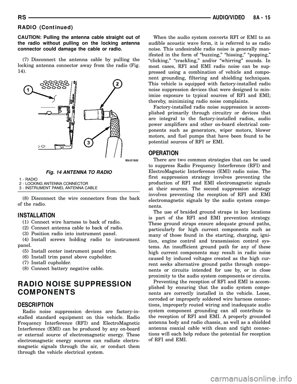
(7) Disconnect the antenna cable by pulling the
locking antenna connector away from the radio (Fig.
14).
(8) Disconnect the wire connectors from the back
of the radio.
INSTALLATION
(1) Connect wire harness to back of radio.
(2) Connect antenna cable to back of radio.
(3) Position radio into instrument panel.
(4) Install screws holding radio to instrument
panel.
(5) Install center instrument panel trim.
(6) Install trim panel above cupholder.
(7) Install cupholder.
(8) Connect battery negative cable.
RADIO NOISE SUPPRESSION
COMPONENTS
DESCRIPTION
Radio noise suppression devices are factory-in-
stalled standard equipment on this vehicle. Radio
Frequency Interference (RFI) and ElectroMagnetic
Interference (EMI) can be produced by any on-board
or external source of electromagnetic energy. These
electromagnetic energy sources can radiate electro-
magnetic signals through the air, or conduct them
through the vehicle electrical system.When the audio system converts RFI or EMI to an
audible acoustic wave form, it is referred to as radio
noise. This undesirable radio noise is generally man-
ifested in the form of ªbuzzing,º ªhissing,º ªpopping,º
ªclicking,º ªcrackling,º and/or ªwhirringº sounds. In
most cases, RFI and EMI radio noise can be sup-
pressed using a combination of vehicle and compo-
nent grounding, filtering and shielding techniques.
This vehicle is equipped with factory-installed radio
noise suppression devices that were designed to min-
imize exposure to typical sources of RFI and EMI;
thereby, minimizing radio noise complaints.
Factory-installed radio noise suppression is accom-
plished primarily through circuitry or devices that
are integral to the factory-installed radios, audio
power amplifiers and other on-board electrical com-
ponents such as generators, wiper motors, blower
motors, and fuel pumps that have been found to be
potential sources of RFI or EMI.
OPERATION
There are two common strategies that can be used
to suppress Radio Frequency Interference (RFI) and
ElectroMagnetic Interference (EMI) radio noise. The
first suppression strategy involves preventing the
production of RFI and EMI electromagnetic signals
at their sources. The second suppression strategy
involves preventing the reception of RFI and EMI
electromagnetic signals by the audio system compo-
nents.
The use of braided ground straps in key locations
is part of the RFI and EMI prevention strategy.
These ground straps ensure adequate ground paths,
particularly for high current components such as
many of those found in the starting, charging, igni-
tion, engine control and transmission control sys-
tems. An insufficient ground path for any of these
high current components may result in radio noise
caused by induced voltages created as the high cur-
rent seeks alternative ground paths through compo-
nents or circuits intended for use by, or in close
proximity to the audio system components or circuits.
Preventing the reception of RFI and EMI is accom-
plished by ensuring that the audio system compo-
nents are correctly installed in the vehicle. Loose,
corroded or improperly soldered wire harness connec-
tions, improperly routed wiring and inadequate audio
system component grounding can all contribute to
the reception of RFI and EMI. A properly grounded
antenna body and radio chassis, as well as a shielded
antenna coaxial cable with clean and tight connec-
tions will each help reduce the potential for reception
of RFI and EMI.
Fig. 14 ANTENNA TO RADIO
1 - RADIO
2 - LOCKING ANTENNA CONNECTOR
3 - INSTRUMENT PANEL ANTENNA CABLE
RSAUDIO/VIDEO8A-15
RADIO (Continued)
Page 374 of 2339
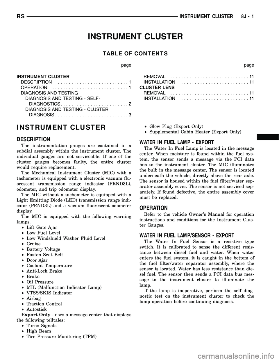
INSTRUMENT CLUSTER
TABLE OF CONTENTS
page page
INSTRUMENT CLUSTER
DESCRIPTION..........................1
OPERATION............................1
DIAGNOSIS AND TESTING
DIAGNOSIS AND TESTING - SELF-
DIAGNOSTICS.........................2
DIAGNOSIS AND TESTING - CLUSTER
DIAGNOSIS...........................3REMOVAL.............................11
INSTALLATION.........................11
CLUSTER LENS
REMOVAL.............................11
INSTALLATION.........................11
INSTRUMENT CLUSTER
DESCRIPTION
The instrumentation gauges are contained in a
subdial assembly within the instrument cluster. The
individual gauges are not serviceable. If one of the
cluster gauges becomes faulty, the entire cluster
would require replacement.
The Mechanical Instrument Cluster (MIC) with a
tachometer is equipped with a electronic vacuum flu-
orescent transmission range indicator (PRND3L),
odometer, and trip odometer display.
The MIC without a tachometer is equipped with a
Light Emitting Diode (LED) transmission range indi-
cator (PRND3L) and a vacuum fluorescent odometer
display.
The MIC is equipped with the following warning
lamps.
²Lift Gate Ajar
²Low Fuel Level
²Low Windshield Washer Fluid Level
²Cruise
²Battery Voltage
²Fasten Seat Belt
²Door Ajar
²Coolant Temperature
²Anti-Lock Brake
²Brake
²Oil Pressure
²MIL (Malfunction Indicator Lamp)
²VTSS/SKIS Indicator
²Airbag
²Traction Control
²Autostick
Export Only- uses a message center that displays
the following telltales:
²Turns Signals
²High Beam
²Tire Pressure Monitoring (TPM)²Glow Plug (Export Only)
²Supplemental Cabin Heater (Export Only)WATER IN FUEL LAMP - EXPORT
The Water In Fuel Lamp is located in the message
center. When moisture is found within the fuel sys-
tem, the sensor sends a message via the PCI data
bus to the instrument cluster. The MIC illuminates
the bulb in the message center, The sensor is located
underneath the vehicle, directly above the rear axle.
The sensor is housed within the fuel filter/water sep-
arator assembly cover. The sensor is not serviced sep-
arately. If found defective, the entire assembly cover
must be replaced.
OPERATION
Refer to the vehicle Owner's Manual for operation
instructions and conditions for the Instrument Clus-
ter Gauges.
WATER IN FUEL LAMP/SENSOR - EXPORT
The Water In Fuel Sensor is a resistive type
switch. It is calibrated to sense the different resis-
tance between diesel fuel and water. When water
enters the fuel system, it is caught in the bottom of
the fuel filter/water separator assembly, where the
sensor is located. Water has less resistance than die-
sel fuel. The sensor then sends a PCI data bus mes-
sage to the instrument cluster to illuminate the
lamp.
If the lamp is inoperative, perform the self diag-
nostic test on the instrument cluster to check the
lamp operation before continuing diagnosis.
RSINSTRUMENT CLUSTER8J-1
Page 1181 of 2339

DIAGNOSIS AND TESTING - ENGINE DIAGNOSIS - PERFORMANCE
CONDITION POSSIBLE CAUSE CORRECTION
ENGINE WILL NOT START 1. Weak battery. 1. Test battery. Charge or replace
as necessary. (Refer to 8 -
ELECTRICAL/BATTERY SYSTEM -
DIAGNOSIS AND TESTING)
2. Corroded or loose battery
connections.2. Clean and tighten battery
connections. Apply a coat of light
mineral grease to terminals.
3. Faulty starter. 3. Test starting system. (Refer to 8 -
ELECTRICAL/STARTING -
DIAGNOSIS AND TESTING)
4. Faulty coil(s) or control unit. 4. Test and replace as needed.
(Refer to Appropriate Diagnostic
Information)
5. Incorrect spark plug gap. 5. Set gap. (Refer to 8 -
ELECTRICAL/IGNITION CONTROL
- SPECIFICATIONS)
6. Contamination in fuel system. 6. Clean system and replace fuel
filter.
7. Faulty fuel pump. 7. Test fuel pump and replace as
needed. (Refer to Appropriate
Diagnostic Information)
8. Incorrect engine timing. 8. Check for a skipped timing
belt/chain.
ENGINE STALLS OR IDLES
ROUGH1. Idle speed too low. 1. Test minimum air flow. (Refer to
Appropriate Diagnostic Information)
2. Incorrect fuel mixture. 2. (Refer to Appropriate Diagnostic
Information)
3. Intake manifold leakage. 3. Inspect intake manifold, manifold
gasket, and vacuum hoses.
4. Faulty ignition coil(s). 4. Test and replace as necessary.
(Refer to Appropriate Diagnostic
Information)
9 - 4 ENGINE 2.4LRS
ENGINE 2.4L (Continued)
Page 1183 of 2339
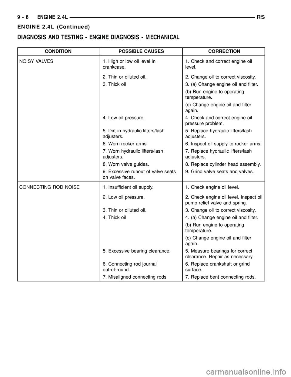
DIAGNOSIS AND TESTING - ENGINE DIAGNOSIS - MECHANICAL
CONDITION POSSIBLE CAUSES CORRECTION
NOISY VALVES 1. High or low oil level in
crankcase.1. Check and correct engine oil
level.
2. Thin or diluted oil. 2. Change oil to correct viscosity.
3. Thick oil 3. (a) Change engine oil and filter.
(b) Run engine to operating
temperature.
(c) Change engine oil and filter
again.
4. Low oil pressure. 4. Check and correct engine oil
pressure problem.
5. Dirt in hydraulic lifters/lash
adjusters.5. Replace hydraulic lifters/lash
adjusters.
6. Worn rocker arms. 6. Inspect oil supply to rocker arms.
7. Worn hydraulic lifters/lash
adjusters.7. Replace hydraulic lifters/lash
adjusters.
8. Worn valve guides. 8. Replace cylinder head assembly.
9. Excessive runout of valve seats
on valve faces.9. Grind valve seats and valves.
CONNECTING ROD NOISE 1. Insufficient oil supply. 1. Check engine oil level.
2. Low oil pressure. 2. Check engine oil level. Inspect oil
pump relief valve and spring.
3. Thin or diluted oil. 3. Change oil to correct viscosity.
4. Thick oil 4. (a) Change engine oil and filter.
(b) Run engine to operating
temperature.
(c) Change engine oil and filter
again.
5. Excessive bearing clearance. 5. Measure bearings for correct
clearance. Repair as necessary.
6. Connecting rod journal
out-of-round.6. Replace crankshaft or grind
surface.
7. Misaligned connecting rods. 7. Replace bent connecting rods.
9 - 6 ENGINE 2.4LRS
ENGINE 2.4L (Continued)