battery replacement CHRYSLER VOYAGER 2005 User Guide
[x] Cancel search | Manufacturer: CHRYSLER, Model Year: 2005, Model line: VOYAGER, Model: CHRYSLER VOYAGER 2005Pages: 2339, PDF Size: 59.69 MB
Page 335 of 2339

(7) Install the right front lower splash shield.
(8) Lower vehicle.
(9) Connect battery negative cable.
VOLTAGE REGULATOR
DESCRIPTION
The Electronic Voltage Regulator (EVR) is not a
separate component. It is actually a voltage regulat-ing circuit located within the Powertrain Control
Module (PCM). The EVR is not serviced separately. If
replacement is necessary, the PCM must be replaced.
OPERATION
The amount of DC current produced by the gener-
ator is controlled by EVR circuitry contained within
the PCM. This circuitry is connected in series with
the generators second rotor field terminal and its
ground.
Voltage is regulated within the PCM on the NGC
vehicles, to control the strength of the rotor magnetic
field. The EVR circuitry monitors system line voltage
at the PDC and calculated battery temperature or
inlet air temperature sensor (refer to Inlet Air Tem-
perature Sensor, if equipped, for more information ).
It then determines a target charging voltage. If
sensed battery voltage is lower than the target volt-
age, the PCM feeds the field winding until sensed
battery voltage is at the target voltage. A circuit in
the PCM cycles the feed side of the generator field at
250 times per second (250Hz), but has the capability
to feed the field control wire 100% of the time (full
field) to achieve the target voltage. If the charging
rate cannot be monitored (limp-in), a duty cycle of
20% is used by the PCM in order to have some gen-
erator output. Also refer to Charging System Opera-
tion for additional information.
Fig. 15 DECOUPLER INSTALLATION (Litens)
8F - 30 CHARGINGRS
GENERATOR DECOUPLER PULLEY (Continued)
Page 357 of 2339
1&4). There should be continuity. If OK, (Refer to 8 -
ELECTRICAL/ELECTRONIC CONTROL MOD-
ULES/MEMORY HEATED SEAT/MIRROR MOD-
ULE - DIAGNOSIS AND TESTING) for complete
system testing procedures. If not OK, install a
replacement heated seat cushion element, (Refer to 8
- ELECTRICAL/HEATED SEATS/HEATED SEAT
ELEMENT - INSTALLATION).
SEAT BACK ELEMENT
(1) From under the vehicle, remove the appropri-
ate seats four retaining nuts.
(2) From inside the vehicle, pull the seat up and
off the mounting studs and lay it back, up against
one of the rear seats.
(3) Locate the heated seat module, attached to the
bottom of the seat cushion pan. Remove the heated
seat module from the seat cushion pan. Do not dis-
connect the electrical connectors at this time.
(4) Locate and disconnect the gray 2-way electrical
connector, connected to the heated seat module.
(5) Check for continuity between the two circuit
cavities of the 2-way wire harness connector. There
should be continuity. If OK, (Refer to 8 - ELECTRI-
CAL/ELECTRONIC CONTROL MODULES/MEM-
ORY HEATED SEAT/MIRROR MODULE -
DIAGNOSIS AND TESTING) for complete system
testing procedures. If not OK, install a replacement
heated seat back element, (Refer to 8 - ELECTRI-
CAL/HEATED SEATS/HEATED SEAT ELEMENT -
INSTALLATION).
REMOVAL
NOTE: Do not remove the factory installed heating
elements from the seat or seat back cushions. The
original element is permanently attached and can-
not be removed without permanent damage. The
replacement heating element is designed to be
applied directly on top of the factory installed heat-
ing element.
(1) Disconnect and isolate the battery negative
cable.
(2) Remove the appropriate seat cushion or seat
back trim cover.
(3) Disconnect the inoperative heated seat cushion
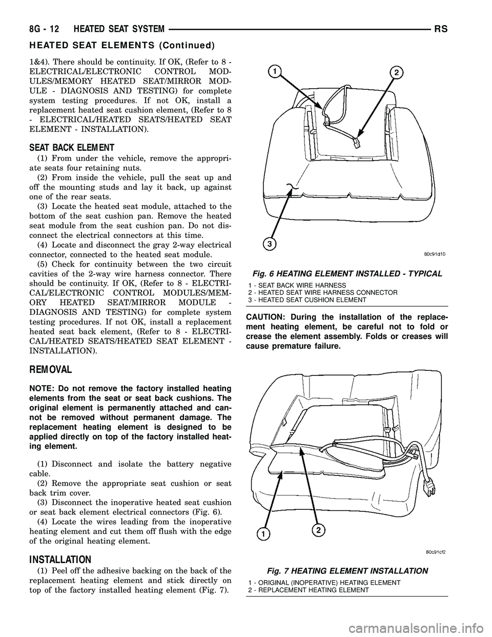
or seat back element electrical connectors (Fig. 6).
(4) Locate the wires leading from the inoperative
heating element and cut them off flush with the edge
of the original heating element.
INSTALLATION
(1) Peel off the adhesive backing on the back of the
replacement heating element and stick directly on
top of the factory installed heating element (Fig. 7).CAUTION: During the installation of the replace-
ment heating element, be careful not to fold or
crease the element assembly. Folds or creases will
cause premature failure.
Fig. 6 HEATING ELEMENT INSTALLED - TYPICAL
1 - SEAT BACK WIRE HARNESS
2 - HEATED SEAT WIRE HARNESS CONNECTOR
3 - HEATED SEAT CUSHION ELEMENT
Fig. 7 HEATING ELEMENT INSTALLATION
1 - ORIGINAL (INOPERATIVE) HEATING ELEMENT
2 - REPLACEMENT HEATING ELEMENT
8G - 12 HEATED SEAT SYSTEMRS
HEATED SEAT ELEMENTS (Continued)
Page 374 of 2339
INSTRUMENT CLUSTER
TABLE OF CONTENTS
page page
INSTRUMENT CLUSTER
DESCRIPTION..........................1
OPERATION............................1
DIAGNOSIS AND TESTING
DIAGNOSIS AND TESTING - SELF-
DIAGNOSTICS.........................2
DIAGNOSIS AND TESTING - CLUSTER
DIAGNOSIS...........................3REMOVAL.............................11
INSTALLATION.........................11
CLUSTER LENS
REMOVAL.............................11
INSTALLATION.........................11
INSTRUMENT CLUSTER
DESCRIPTION
The instrumentation gauges are contained in a
subdial assembly within the instrument cluster. The
individual gauges are not serviceable. If one of the
cluster gauges becomes faulty, the entire cluster
would require replacement.
The Mechanical Instrument Cluster (MIC) with a
tachometer is equipped with a electronic vacuum flu-
orescent transmission range indicator (PRND3L),
odometer, and trip odometer display.
The MIC without a tachometer is equipped with a
Light Emitting Diode (LED) transmission range indi-
cator (PRND3L) and a vacuum fluorescent odometer
display.
The MIC is equipped with the following warning
lamps.
²Lift Gate Ajar
²Low Fuel Level
²Low Windshield Washer Fluid Level
²Cruise
²Battery Voltage
²Fasten Seat Belt
²Door Ajar
²Coolant Temperature
²Anti-Lock Brake
²Brake
²Oil Pressure
²MIL (Malfunction Indicator Lamp)
²VTSS/SKIS Indicator
²Airbag
²Traction Control
²Autostick
Export Only- uses a message center that displays
the following telltales:
²Turns Signals
²High Beam
²Tire Pressure Monitoring (TPM)²Glow Plug (Export Only)
²Supplemental Cabin Heater (Export Only)WATER IN FUEL LAMP - EXPORT
The Water In Fuel Lamp is located in the message
center. When moisture is found within the fuel sys-
tem, the sensor sends a message via the PCI data
bus to the instrument cluster. The MIC illuminates
the bulb in the message center, The sensor is located
underneath the vehicle, directly above the rear axle.
The sensor is housed within the fuel filter/water sep-
arator assembly cover. The sensor is not serviced sep-
arately. If found defective, the entire assembly cover
must be replaced.
OPERATION
Refer to the vehicle Owner's Manual for operation
instructions and conditions for the Instrument Clus-
ter Gauges.
WATER IN FUEL LAMP/SENSOR - EXPORT
The Water In Fuel Sensor is a resistive type
switch. It is calibrated to sense the different resis-
tance between diesel fuel and water. When water
enters the fuel system, it is caught in the bottom of
the fuel filter/water separator assembly, where the
sensor is located. Water has less resistance than die-
sel fuel. The sensor then sends a PCI data bus mes-
sage to the instrument cluster to illuminate the
lamp.
If the lamp is inoperative, perform the self diag-
nostic test on the instrument cluster to check the
lamp operation before continuing diagnosis.
RSINSTRUMENT CLUSTER8J-1
Page 407 of 2339
DOME/CARGO LAMP
REMOVAL
(1) Disconnect and isolate the battery negative
cable.
(2) Using a flat bladed tool, pry off the lamp lens.
(3) Remove bulb from lamp.
INSTALLATION
(1) Install bulb to lamp.
(2) Press lens into place.
(3) Connect battery negative cable.
GLOVE BOX LAMP SWITCH
REMOVAL
(1) Disconnect and isolate the battery negative
cable.
(2) Open glove box door.
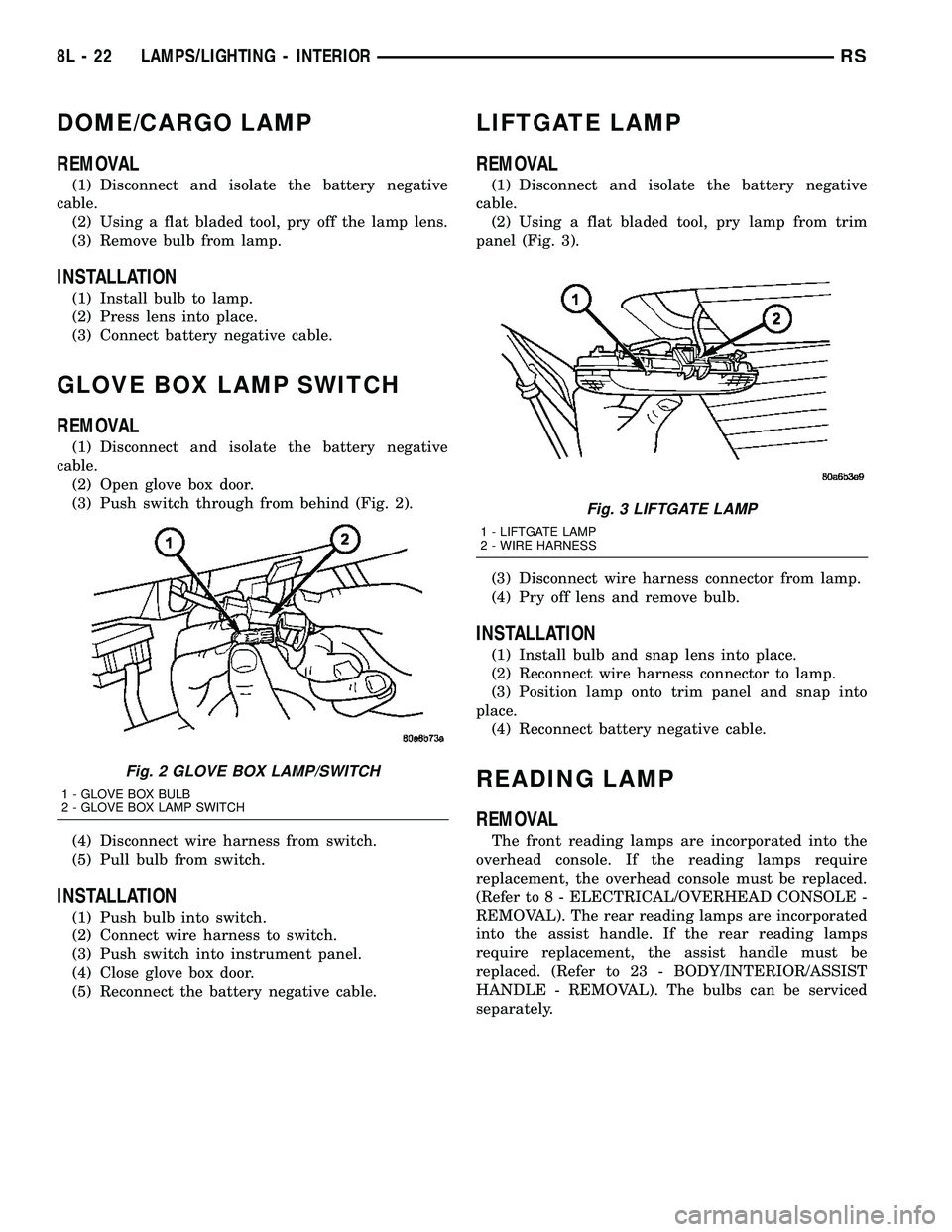
(3) Push switch through from behind (Fig. 2).
(4) Disconnect wire harness from switch.
(5) Pull bulb from switch.
INSTALLATION
(1) Push bulb into switch.
(2) Connect wire harness to switch.
(3) Push switch into instrument panel.
(4) Close glove box door.
(5) Reconnect the battery negative cable.
LIFTGATE LAMP
REMOVAL
(1) Disconnect and isolate the battery negative
cable.
(2) Using a flat bladed tool, pry lamp from trim
panel (Fig. 3).
(3) Disconnect wire harness connector from lamp.
(4) Pry off lens and remove bulb.
INSTALLATION
(1) Install bulb and snap lens into place.
(2) Reconnect wire harness connector to lamp.
(3) Position lamp onto trim panel and snap into
place.
(4) Reconnect battery negative cable.
READING LAMP
REMOVAL
The front reading lamps are incorporated into the
overhead console. If the reading lamps require
replacement, the overhead console must be replaced.
(Refer to 8 - ELECTRICAL/OVERHEAD CONSOLE -
REMOVAL). The rear reading lamps are incorporated
into the assist handle. If the rear reading lamps
require replacement, the assist handle must be
replaced. (Refer to 23 - BODY/INTERIOR/ASSIST
HANDLE - REMOVAL). The bulbs can be serviced
separately.
Fig. 2 GLOVE BOX LAMP/SWITCH
1 - GLOVE BOX BULB
2 - GLOVE BOX LAMP SWITCH
Fig. 3 LIFTGATE LAMP
1 - LIFTGATE LAMP
2 - WIRE HARNESS
8L - 22 LAMPS/LIGHTING - INTERIORRS
Page 426 of 2339

travel is accomplished by hall effect sensors, drive
motor speed and pinch sensors (tape switches).
Anytime the liftgate is opened or closed using the
power liftgate system the power liftgate control mod-
ule learns from the cycle. If a replacement power lift-
gate component is installed or a liftgate adjustment
is made, the module will relearn the effort and/or
time required to open or close the liftgate. This learn
cycle can be performed with a DRB IIIt, or equiva-
lent scan tool, or with a complete cycle of the liftgate,
using any one of the command switches. (Refer to 8 -
ELECTRICAL/POWER DOORS - STANDARD PRO-
CEDURE) for detailed instructions.
The power liftgate system is designed with a num-
ber of system inhibitors. These inhibitors are neces-
sary for safety and / or feasibility of the power
liftgate system. The power liftgate system inhibitors
are:
²The Power Liftgate may not operate in extreme
temperatures. These extreme temperatures will be
approximately less than -12É F (-24.4É C) or greater
than 143É F (61.6É C). A chime/thermister assembly
in the rear light bar assembly monitors the outside
temperature.
²The vehicle transmission must be in Park or
Neutral for the power liftgate to start a cycle.
²If multiple obstacles are detected during the
same power open or close cycle, the liftgate goes into
manual operation.
²If severe problems occur, Diagnostic Trouble
Codes (DTC) are stored in the power liftgate control
module.
POWER LIFTGATE SYSTEM CAUTIONS AND
WARNINGS
WARNING: ALWAYS DISCONNECT THE BATTERY
NEGATIVE CABLE BEFORE ATTEMPTING ANY
POWER LIFTGATE SYSTEM SERVICE.
WARNING: THERE IS A SMALL AREA ON BOTH
SIDES OF THE LOWER POWER LIFTGATE WHICH
IS NOT PROTECTED BY PINCH SENSORS.
EXTREME CARE MUST BE TAKEN TO PREVENT
OBJECTS FROM ENTERING THIS AREA ONCE THELIFTGATE REACHES THE SECONDARY LATCH
CONTACT (APPROXIMATELY 1/2 INCH BEFORE
FULLY CLOSED).
WARNING: NEVER ATTEMPT TO ENTER OR EXIT
THE VEHICLE WITH THE LIFTGATE IN MOTION.
YOU COULD DAMAGE THE POWER LIFTGATE SYS-
TEM AND/OR COMPONENTS AND/OR CAUSE PER-
SONAL INJURY.
WARNING: NEVER STICK OBJECTS IN THE POWER
LIFTGATE WHEN CINCHING CLOSED. YOU COULD
DAMAGE THE VEHICLE, POWER LIFTGATE SYS-
TEM COMPONENTS AND/OR CAUSE PERSONAL
INJURY.
DIAGNOSIS AND TESTING
POWER LIFTGATE SYSTEM
The power liftgate system contains many compo-
nents and modules. In order to obtain conclusive
testing the Programmable Communications Interface
(PCI) data bus network and all of the electronic mod-
ules that provide inputs to, or receive outputs from
the power liftgate system must be checked.
The power liftgate system can be diagnosed with
an appropriate scan tool, such as the DRB IIItor
equivalent. The DRB IIItcan be used to observe var-
ious switch statuses throughout the power liftgate
system to help diagnose an inoperative switch or
component. The DRB IIItcan also be used to actuate
various components throughout the power liftgate
system to help diagnose an inoperative component.
Before any testing of the power liftgate system is
attempted, the battery should be fully charged, all
built-in power liftgate system inhibitors read and
understood, and all wire harness and ground connec-
tions inspected around the affected areas on the vehi-
cle.
The following are quick reference diagnostic tables
to help when diagnosing and testing the power lift-
gate system.
RSPOWER LIFTGATE SYSTEM8N-3
POWER LIFTGATE SYSTEM (Continued)
Page 438 of 2339
LIFTGATE MOTOR
DESCRIPTION
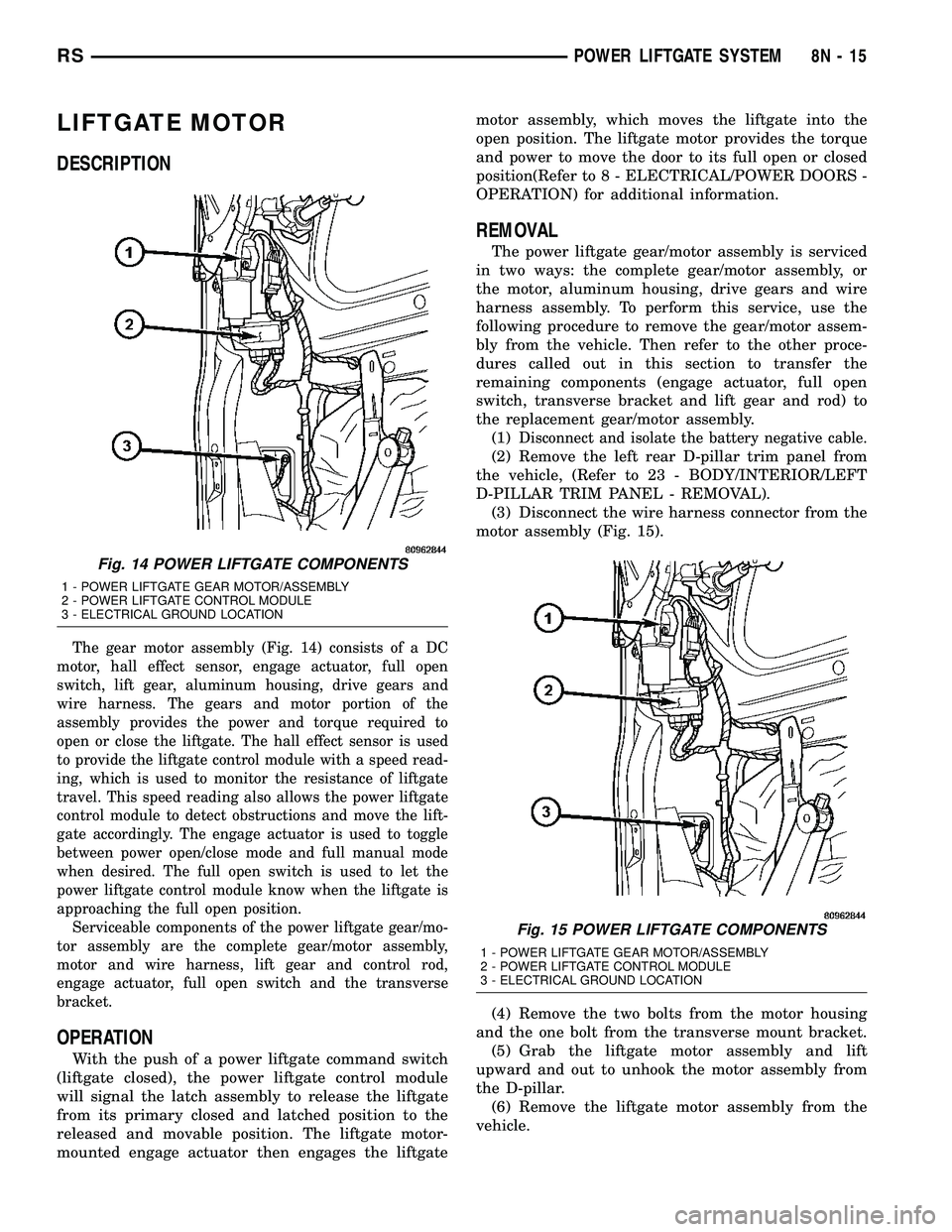
The gear motor assembly (Fig. 14) consists of a DC
motor, hall effect sensor, engage actuator, full open
switch, lift gear, aluminum housing, drive gears and
wire harness. The gears and motor portion of the
assembly provides the power and torque required to
open or close the liftgate. The hall effect sensor is used
to provide the liftgate control module with a speed read-
ing, which is used to monitor the resistance of liftgate
travel. This speed reading also allows the power liftgate
control module to detect obstructions and move the lift-
gate accordingly. The engage actuator is used to toggle
between power open/close mode and full manual mode
when desired. The full open switch is used to let the
power liftgate control module know when the liftgate is
approaching the full open position.
Serviceable components of the power liftgate gear/mo-
tor assembly are the complete gear/motor assembly,
motor and wire harness, lift gear and control rod,
engage actuator, full open switch and the transverse
bracket.
OPERATION
With the push of a power liftgate command switch
(liftgate closed), the power liftgate control module
will signal the latch assembly to release the liftgate
from its primary closed and latched position to the
released and movable position. The liftgate motor-
mounted engage actuator then engages the liftgatemotor assembly, which moves the liftgate into the
open position. The liftgate motor provides the torque
and power to move the door to its full open or closed
position(Refer to 8 - ELECTRICAL/POWER DOORS -
OPERATION) for additional information.
REMOVAL
The power liftgate gear/motor assembly is serviced
in two ways: the complete gear/motor assembly, or
the motor, aluminum housing, drive gears and wire
harness assembly. To perform this service, use the
following procedure to remove the gear/motor assem-
bly from the vehicle. Then refer to the other proce-
dures called out in this section to transfer the
remaining components (engage actuator, full open
switch, transverse bracket and lift gear and rod) to
the replacement gear/motor assembly.
(1)
Disconnect and isolate the battery negative cable.
(2) Remove the left rear D-pillar trim panel from
the vehicle, (Refer to 23 - BODY/INTERIOR/LEFT
D-PILLAR TRIM PANEL - REMOVAL).
(3) Disconnect the wire harness connector from the
motor assembly (Fig. 15).
(4) Remove the two bolts from the motor housing
and the one bolt from the transverse mount bracket.
(5) Grab the liftgate motor assembly and lift
upward and out to unhook the motor assembly from
the D-pillar.
(6) Remove the liftgate motor assembly from the
vehicle.
Fig. 14 POWER LIFTGATE COMPONENTS
1 - POWER LIFTGATE GEAR MOTOR/ASSEMBLY
2 - POWER LIFTGATE CONTROL MODULE
3 - ELECTRICAL GROUND LOCATION
Fig. 15 POWER LIFTGATE COMPONENTS
1 - POWER LIFTGATE GEAR MOTOR/ASSEMBLY
2 - POWER LIFTGATE CONTROL MODULE
3 - ELECTRICAL GROUND LOCATION
RSPOWER LIFTGATE SYSTEM8N-15
Page 443 of 2339
POWER LOCKS
TABLE OF CONTENTS
page page
POWER LOCKS
DESCRIPTION.........................20
OPERATION...........................21
DOOR CYLINDER LOCK SWITCH - EXPORT
DESCRIPTION.........................22
OPERATION...........................22
DIAGNOSIS AND TESTING
DOOR CYLINDER LOCK SWITCH -
EXPORT............................22
REMOVAL.............................22
INSTALLATION.........................22
DOOR LOCK MOTOR
DIAGNOSIS AND TESTING
DOOR LOCK MOTOR..................23
DOOR LOCK SWITCH
DIAGNOSIS AND TESTING
DOOR LOCK SWITCH..................23
REMOVAL.............................23INSTALLATION.........................23
KEYLESS ENTRY TRANSMITTER
DIAGNOSIS AND TESTING
KEYLESS ENTRY TRANSMITTER.........24
STANDARD PROCEDURE
STANDARD PROCEDURE - HORN CHIRP
PREFERENCE........................24
STANDARD PROCEDURE - BATTERY
REPLACEMENT.......................24
STANDARD PROCEDURE - REMOTE
KEYLESS ENTRY TRANSMITTER
PROGRAMMING......................24
SPECIFICATIONS
SPECIFICATIONS - TRANSMITTER RANGE . 24
SPECIFICATIONS - BATTERY............24
SLIDING DOOR LOCK MOTOR
REMOVAL.............................25
INSTALLATION.........................25
POWER LOCKS
DESCRIPTION
POWER LOCKS
The power lock system allows all of the doors to be
locked or unlocked electrically by operating a switch
on either front door trim panel. The power lock sys-
tem receives non-switched battery current through a
fuse in the Integrated Power Module (IPM), so that
the power locks remain operational, regardless of the
ignition switch position.
The Body Control Module (BCM) locks the doors
automatically when the vehicle is driven beyond the
speed of 25.7 Km/h (15 mph), all doors are closed, the
accelerator pedal is depressed and the door lock actu-
ation had not been previously activated. The rolling
door lock feature is customer programmable.
This vehicle also offers several customer program-
mable features, which allows the selection of several
optional electronic features to suit individual prefer-
ences.
The power lock system for this vehicle can also be
operated remotely using the available Remote Key-
less Entry (RKE) system radio frequency transmit-
ters, if equipped.
AUTOMATIC DOOR LOCKS
When enabled, this feature will lock all of the door
locks if all of the doors are closed and the vehicle
speed goes above 25.7 km/h (15 mph). If a door
unlock has occurred, then the BCM will perform
another auto lock, if the doors did not electrically
unlock, another auto lock will not occur.
DOOR LOCK INHIBIT
When the key is in the ignition (in any switch posi-
tion) and either front door is opened, the door lock
switches LOCK functions are disabled. The
UN-LOCK functions are still functional. This protects
against locking the vehicle with the key still in the
ignition. The RKE key fob will still lock the doors.
After the key is removed from the ignition or the
doors are closed, the power door locks will operate
normally.
REMOTE KEYLESS ENTRY
The Remote Keyless Entry (RKE) system allows
the use of a remote battery-powered radio transmit-
ter to communicate with the BCM to actuate the
power lock system.
The RKE transmitters are also equipped with a
Panic button. If the Panic button on the RKE trans-
mitter is depressed, the horn will sound and the
exterior lights will flash on the vehicle for about
three minutes, or until the Panic button is depressed
8N - 20 POWER LOCKSRS
Page 447 of 2339
KEYLESS ENTRY
TRANSMITTER
DIAGNOSIS AND TESTING
KEYLESS ENTRY TRANSMITTER
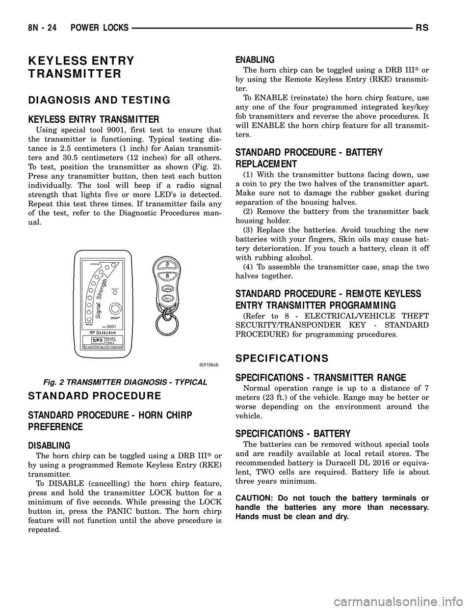
Using special tool 9001, first test to ensure that
the transmitter is functioning. Typical testing dis-
tance is 2.5 centimeters (1 inch) for Asian transmit-
ters and 30.5 centimeters (12 inches) for all others.
To test, position the transmitter as shown (Fig. 2).
Press any transmitter button, then test each button
individually. The tool will beep if a radio signal
strength that lights five or more LED's is detected.
Repeat this test three times. If transmitter fails any
of the test, refer to the Diagnostic Procedures man-
ual.
STANDARD PROCEDURE
STANDARD PROCEDURE - HORN CHIRP
PREFERENCE
DISABLING
The horn chirp can be toggled using a DRB IIItor
by using a programmed Remote Keyless Entry (RKE)
transmitter.
To DISABLE (cancelling) the horn chirp feature,
press and hold the transmitter LOCK button for a
minimum of five seconds. While pressing the LOCK
button in, press the PANIC button. The horn chirp
feature will not function until the above procedure is
repeated.
ENABLING
The horn chirp can be toggled using a DRB IIItor
by using the Remote Keyless Entry (RKE) transmit-
ter.
To ENABLE (reinstate) the horn chirp feature, use
any one of the four programmed integrated key/key
fob transmitters and reverse the above procedures. It
will ENABLE the horn chirp feature for all transmit-
ters.
STANDARD PROCEDURE - BATTERY
REPLACEMENT
(1) With the transmitter buttons facing down, use
a coin to pry the two halves of the transmitter apart.
Make sure not to damage the rubber gasket during
separation of the housing halves.
(2) Remove the battery from the transmitter back
housing holder.
(3) Replace the batteries. Avoid touching the new
batteries with your fingers, Skin oils may cause bat-
tery deterioration. If you touch a battery, clean it off
with rubbing alcohol.
(4) To assemble the transmitter case, snap the two
halves together.
STANDARD PROCEDURE - REMOTE KEYLESS
ENTRY TRANSMITTER PROGRAMMING
(Refer to 8 - ELECTRICAL/VEHICLE THEFT
SECURITY/TRANSPONDER KEY - STANDARD
PROCEDURE) for programming procedures.
SPECIFICATIONS
SPECIFICATIONS - TRANSMITTER RANGE
Normal operation range is up to a distance of 7
meters (23 ft.) of the vehicle. Range may be better or
worse depending on the environment around the
vehicle.
SPECIFICATIONS - BATTERY
The batteries can be removed without special tools
and are readily available at local retail stores. The
recommended battery is Duracell DL 2016 or equiva-
lent, TWO cells are required. Battery life is about
three years minimum.
CAUTION: Do not touch the battery terminals or
handle the batteries any more than necessary.
Hands must be clean and dry.
Fig. 2 TRANSMITTER DIAGNOSIS - TYPICAL
8N - 24 POWER LOCKSRS
Page 464 of 2339
travel. This allows the power sliding door to stop and
reverse direction any time an obstruction is felt or
any of the command switches are operated (while
closing only). Battery voltage is supplied to the power
sliding door system through a 40 amp fuse, located in
the Integrated Power Module (IPM) assembly. The
child lockout switch prevents children from opening
or actuating the power sliding door system when
desired. In the unlikely event that the power sliding
door system develops a fault, the power sliding door
can still be operated manually from the interior or
exterior door handle, just like a standard manual
sliding door.
The power sliding door control module communi-
cates on the Programmable Communication Interface
(PCI) Data Bus Circuit. Therefore, the power sliding
door control module can generate and store its own
Diagnostic Trouble Codes (DTC). A diagnostic scan
tool, such as the DRB IIItis used to read and diag-
nose these trouble codes.
NOTE: It may be possible to generate Sliding Door
Diagnostic Trouble Codes during normal power
sliding door operation. Refer to the Body Diagnos-
tic Manual for a complete list of diagnostic routines.
For additional information, (Refer to 8 - ELECTRI-
CAL/POWER DOORS - OPERATION). Refer to the
appropriate wiring information for complete circuit
schematic or connector pin-out information.WARNING: BE CERTAIN TO READ ALL WARNINGS
AND CAUTIONS IN POWER SLIDING DOOR OPER-
ATION BEFORE ATTEMPTING ANY SERVICE OF
THE POWER SLIDING DOOR SYSTEM OR COMPO-
NENTS.
OPERATION
With the push of a power sliding door open/close
command switch (key fob, overhead console or B-pil-
lar mounted) a signal is sent out to the Body Control
Module (BCM). The BCM then sends a signal out on
the Programmable Communication Interface (PCI)
Data Bus circuit to the power sliding door module.
The power sliding door module then signals the
power sliding door latch to release the door to the
unlatched and movable position. The motor then
starts an open cycle.
During the door cycle, if the power sliding door
module detects sufficient resistance to door travel,
such as an obstruction in the door's path, the power
sliding door module will immediately stop door move-
ment and reverse door travel to the full open or
closed position. The ability for the power sliding door
module to detect resistance to door travel is accom-
plished by hall effect sensors detecting the door
motor speed.
The power sliding door control module has the abil-
ity to learn. Anytime a door is opened or closed using
the power sliding door system the module learns
from its cycle. If a replacement power sliding door
component is installed or a door adjustment is made,
the module must re-learn the effort required to open
or close the door. A learn cycle can be performed with
a complete cycle of the door, using any one of the
command switches or with the DRB IIIt, or equiva-
lent scan tool. (Refer to 8 - ELECTRICAL/POWER
DOORS - STANDARD PROCEDURE - LEARN
CYCLE) for detailed instructions.
The power sliding door system is designed with a
number of system inhibitors. These inhibitors are
necessary for safety and/or feasibility of the power
sliding door system. The power sliding door system
inhibitors are:
²The power sliding door must be in thefullopen
or closed position in order for the power sliding door
system to start a cycle. If the door is not in this posi-
tion (based on the input from the full open, pawl or
ratchet switches) the door control module will not
respond to command switch inputs.
²The transmission must be inpark or neutral
in order for the power sliding door system to start a
cycle.
²The child lockout switch must be in the
ªUNLOCKEDº position in order for the power sliding
door systems B-pillar switches to function.
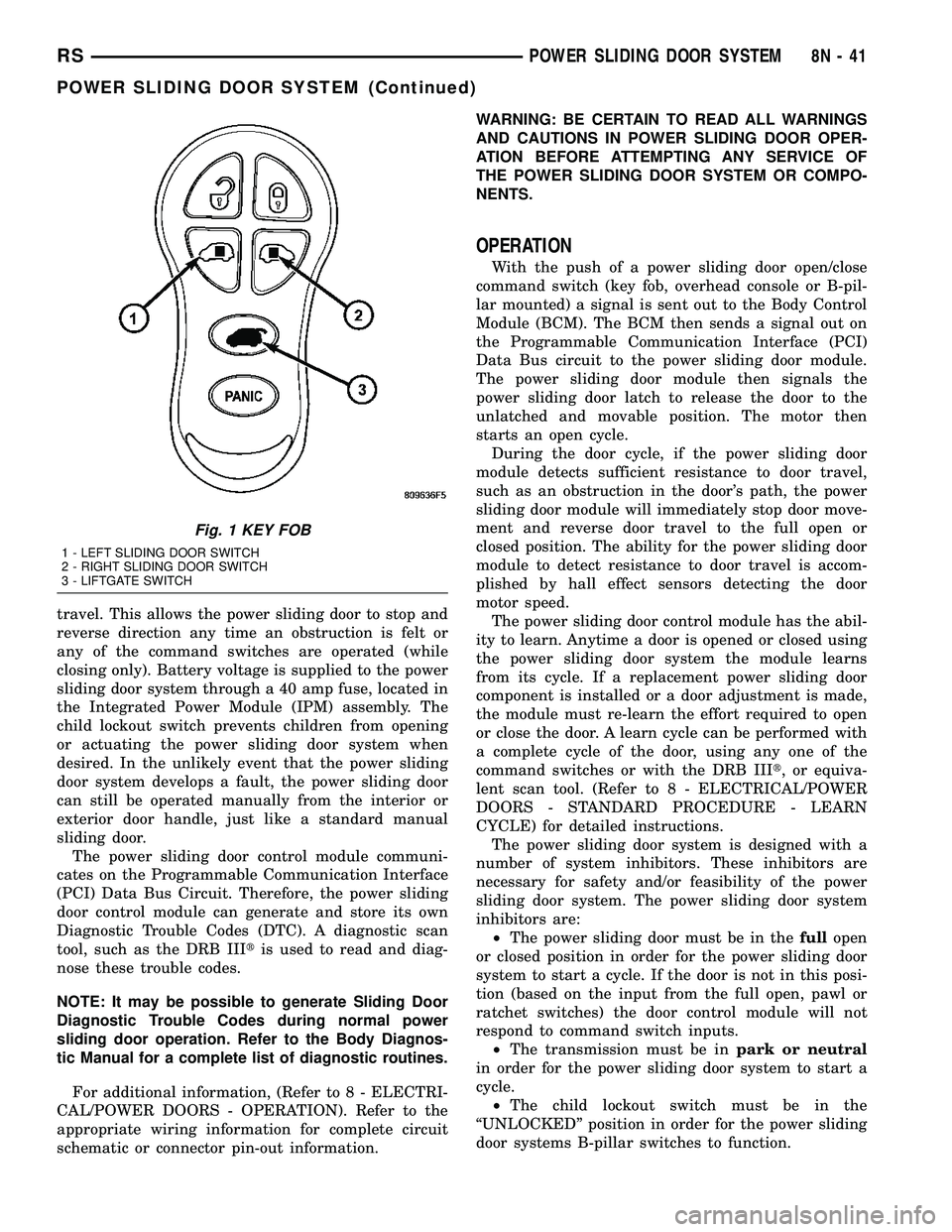
Fig. 1 KEY FOB
1 - LEFT SLIDING DOOR SWITCH
2 - RIGHT SLIDING DOOR SWITCH
3 - LIFTGATE SWITCH
RSPOWER SLIDING DOOR SYSTEM8N-41
POWER SLIDING DOOR SYSTEM (Continued)
Page 473 of 2339

(5) Partially close the door and pull the latch
assembly out of the side door inner panel, (Fig. 5).
(6) Disconnect all electrical connectors leading to
the latch assembly.
(7) Disconnect the inside and outside handle cables
from the latch assembly.
(8) Disconnect the hold open latch cable from the
latch assembly.
(9) Disconnect lock actuator link rod from the
latch assembly.
(10) Remove the latch assembly from the vehicle.
INSTALLATION
(1) Position the latch assembly in the vehicle. Be
certain all latch mounted components are installed
on the replacement latch assembly. If not, transfer
components from the old latch to the new latch
assembly, (Fig. 6).
(2) Connect the lock actuator link rod on the latch
assembly.
(3) Connect the hold open latch cable on the latch
assembly.
(4) Connect the inside and outside handle cables
on the latch assembly.
(5) Connect all electrical connectors leading to the
latch assembly.
(6) With assistance from another person, position
the side door and install the door latch retaining
bolts, (Fig. 7). Torque to 10 - 12 N´m (100 in. lbs.).
(7) Install the weathershield if necessary.(8) Install the appropriate side door trim panel,
(Refer to 23 - BODY/DOORS - SLIDING/TRIM
PANEL - INSTALLATION) for detailed instructions.
(9) Connect the negative battery cable.
Fig. 5 POWER LATCH POSITION & ORIENTATION
1 - POWER LATCH ASSEMBLY
Fig. 6 POWER LATCH POSITION & ORIENTATION
1 - POWER LATCH ASSEMBLY
Fig. 7 REMOVING LATCH RETAINING BOLTS
1 - LATCH RETAINING BOLTS
2 - SIDE DOOR
8N - 50 POWER SLIDING DOOR SYSTEMRS
LATCH (Continued)