tires CHRYSLER VOYAGER 2005 User Guide
[x] Cancel search | Manufacturer: CHRYSLER, Model Year: 2005, Model line: VOYAGER, Model: CHRYSLER VOYAGER 2005Pages: 2339, PDF Size: 59.69 MB
Page 31 of 2339
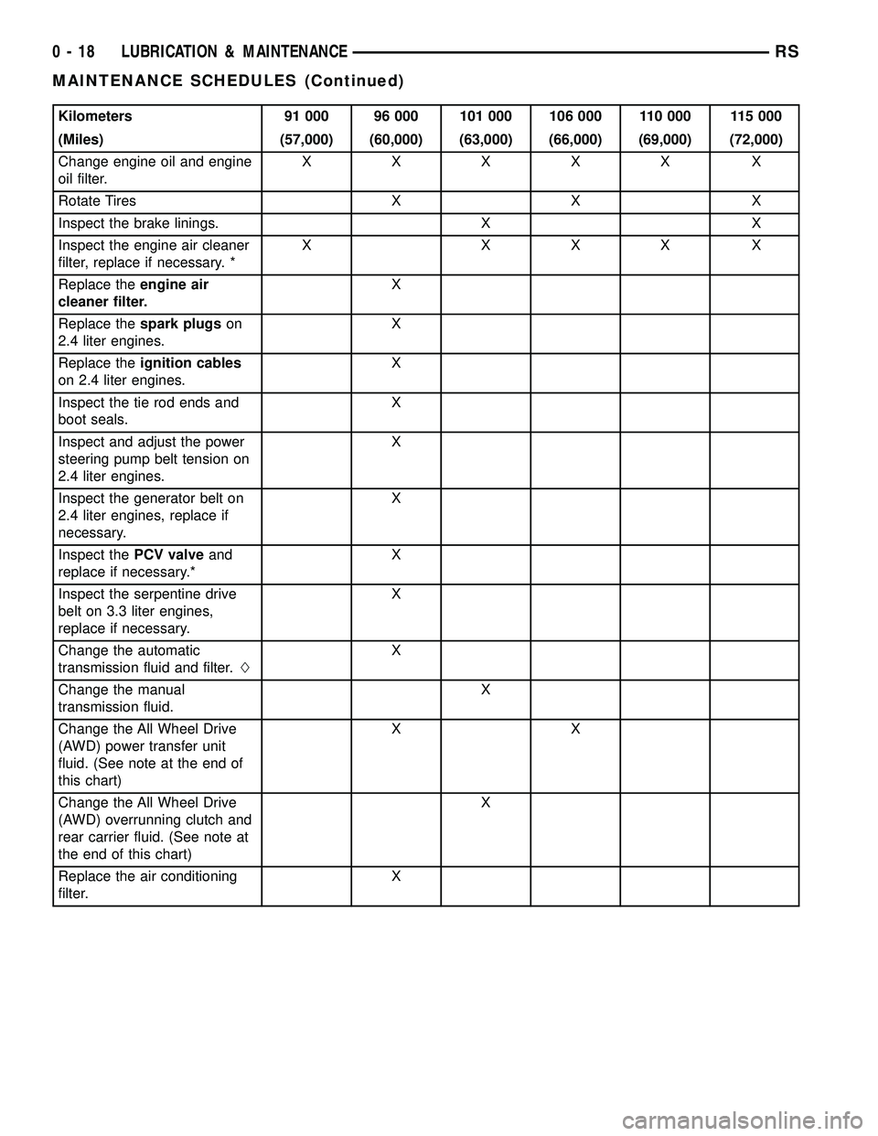
Kilometers 91 000 96 000 101 000 106 000 110 000 115 000
(Miles) (57,000) (60,000) (63,000) (66,000) (69,000) (72,000)
Change engine oil and engine
oil filter.XXXXX X
Rotate Tires X X X
Inspect the brake linings. X X
Inspect the engine air cleaner
filter, replace if necessary. *X XXX X
Replace theengine air
cleaner filter.X
Replace thespark plugson
2.4 liter engines.X
Replace theignition cables
on 2.4 liter engines.X
Inspect the tie rod ends and
boot seals.X
Inspect and adjust the power
steering pump belt tension on
2.4 liter engines.X
Inspect the generator belt on
2.4 liter engines, replace if
necessary.X
Inspect thePCV valveand
replace if necessary.*X
Inspect the serpentine drive
belt on 3.3 liter engines,
replace if necessary.X
Change the automatic
transmission fluid and filter.LX
Change the manual
transmission fluid.X
Change the All Wheel Drive
(AWD) power transfer unit
fluid. (See note at the end of
this chart)XX
Change the All Wheel Drive
(AWD) overrunning clutch and
rear carrier fluid. (See note at
the end of this chart)X
Replace the air conditioning
filter.X
0 - 18 LUBRICATION & MAINTENANCERS
MAINTENANCE SCHEDULES (Continued)
Page 32 of 2339
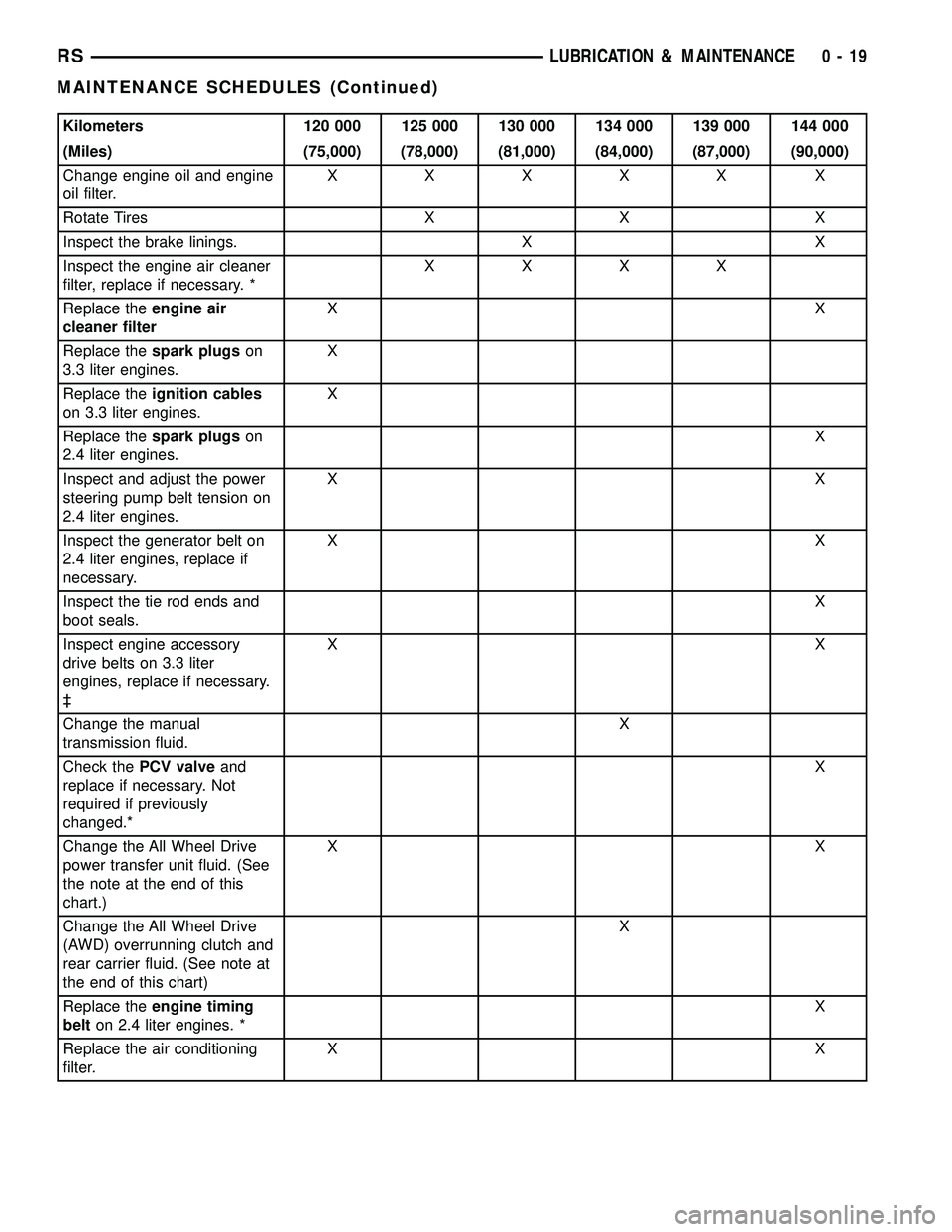
Kilometers 120 000 125 000 130 000 134 000 139 000 144 000
(Miles) (75,000) (78,000) (81,000) (84,000) (87,000) (90,000)
Change engine oil and engine
oil filter.XXXXX X
Rotate Tires X X X
Inspect the brake linings. X X
Inspect the engine air cleaner
filter, replace if necessary. *XXXX
Replace theengine air
cleaner filterXX
Replace thespark plugson
3.3 liter engines.X
Replace theignition cables
on 3.3 liter engines.X
Replace thespark plugson
2.4 liter engines.X
Inspect and adjust the power
steering pump belt tension on
2.4 liter engines.XX
Inspect the generator belt on
2.4 liter engines, replace if
necessary.XX
Inspect the tie rod ends and
boot seals.X
Inspect engine accessory
drive belts on 3.3 liter
engines, replace if necessary.
³XX
Change the manual
transmission fluid.X
Check thePCV valveand
replace if necessary. Not
required if previously
changed.*X
Change the All Wheel Drive
power transfer unit fluid. (See
the note at the end of this
chart.)XX
Change the All Wheel Drive
(AWD) overrunning clutch and
rear carrier fluid. (See note at
the end of this chart)X
Replace theengine timing
belton 2.4 liter engines. *X
Replace the air conditioning
filter.XX
RSLUBRICATION & MAINTENANCE0-19
MAINTENANCE SCHEDULES (Continued)
Page 33 of 2339
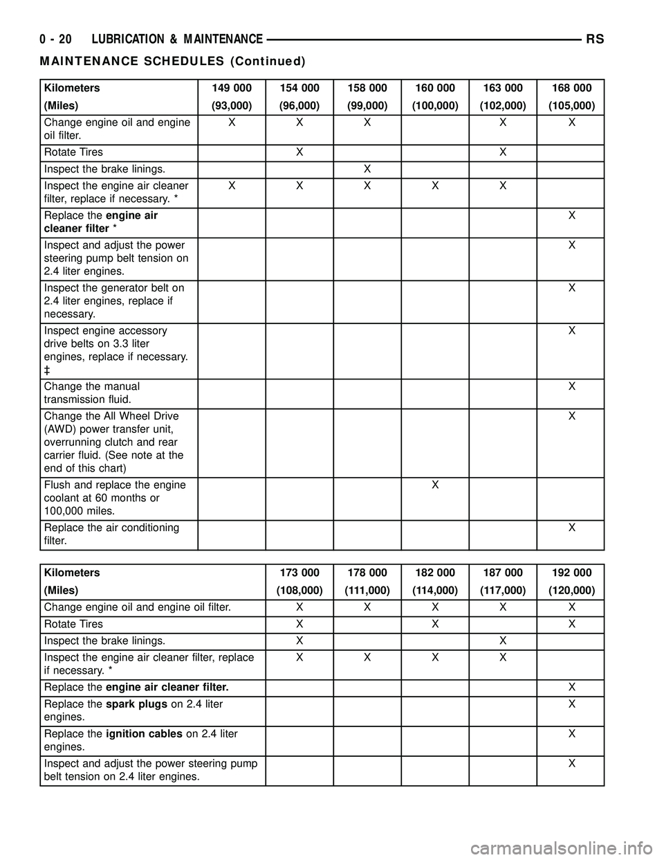
Kilometers 149 000 154 000 158 000 160 000 163 000 168 000
(Miles) (93,000) (96,000) (99,000) (100,000) (102,000) (105,000)
Change engine oil and engine
oil filter.XXX X X
Rotate Tires X X
Inspect the brake linings. X
Inspect the engine air cleaner
filter, replace if necessary. *XXXXX
Replace theengine air
cleaner filter*X
Inspect and adjust the power
steering pump belt tension on
2.4 liter engines.X
Inspect the generator belt on
2.4 liter engines, replace if
necessary.X
Inspect engine accessory
drive belts on 3.3 liter
engines, replace if necessary.
³X
Change the manual
transmission fluid.X
Change the All Wheel Drive
(AWD) power transfer unit,
overrunning clutch and rear
carrier fluid. (See note at the
end of this chart)X
Flush and replace the engine
coolant at 60 months or
100,000 miles.X
Replace the air conditioning
filter.X
Kilometers 173 000 178 000 182 000 187 000 192 000
(Miles) (108,000) (111,000) (114,000) (117,000) (120,000)
Change engine oil and engine oil filter.XXXX X
Rotate Tires X X X
Inspect the brake linings. X X
Inspect the engine air cleaner filter, replace
if necessary. *XXXX
Replace theengine air cleaner filter.X
Replace thespark plugson 2.4 liter
engines.X
Replace theignition cableson 2.4 liter
engines.X
Inspect and adjust the power steering pump
belt tension on 2.4 liter engines.X
0 - 20 LUBRICATION & MAINTENANCERS
MAINTENANCE SCHEDULES (Continued)
Page 35 of 2339
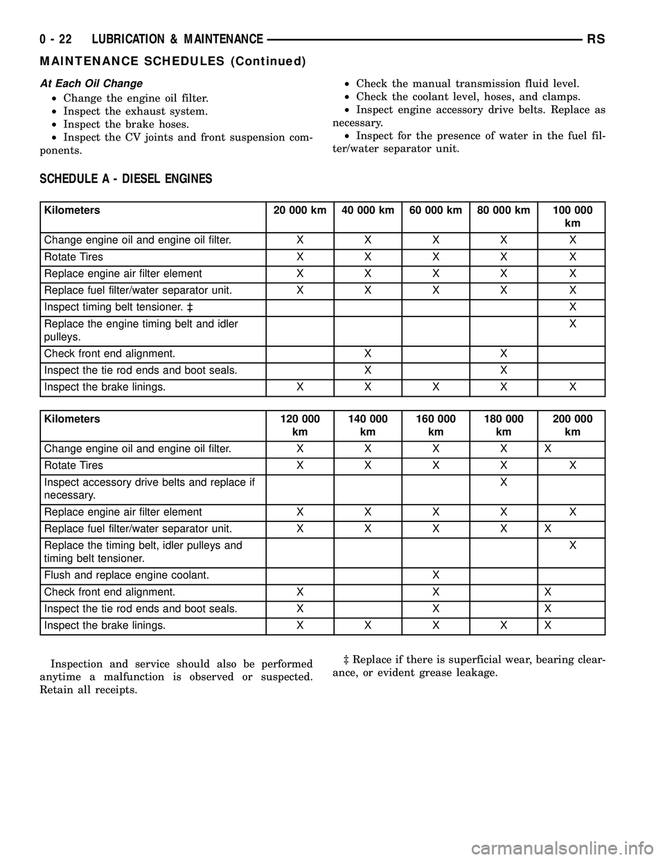
At Each Oil Change
²Change the engine oil filter.
²Inspect the exhaust system.
²Inspect the brake hoses.
²Inspect the CV joints and front suspension com-
ponents.²Check the manual transmission fluid level.
²Check the coolant level, hoses, and clamps.
²Inspect engine accessory drive belts. Replace as
necessary.
²Inspect for the presence of water in the fuel fil-
ter/water separator unit.
SCHEDULE A - DIESEL ENGINES
Kilometers 20 000 km 40 000 km 60 000 km 80 000 km 100 000
km
Change engine oil and engine oil filter.XXXX X
Rotate TiresXXXX X
Replace engine air filter elementXXXX X
Replace fuel filter/water separator unit.XXXX X
Inspect timing belt tensioner. ³X
Replace the engine timing belt and idler
pulleys.X
Check front end alignment. X X
Inspect the tie rod ends and boot seals. X X
Inspect the brake linings.XXXX X
Kilometers 120 000
km140 000
km160 000
km180 000
km200 000
km
Change engine oil and engine oil filter.XXXXX
Rotate TiresXXXX X
Inspect accessory drive belts and replace if
necessary.X
Replace engine air filter elementXXXX X
Replace fuel filter/water separator unit.XXXXX
Replace the timing belt, idler pulleys and
timing belt tensioner.X
Flush and replace engine coolant. X
Check front end alignment. X X X
Inspect the tie rod ends and boot seals. X X X
Inspect the brake linings.XXXXX
Inspection and service should also be performed
anytime a malfunction is observed or suspected.
Retain all receipts.³ Replace if there is superficial wear, bearing clear-
ance, or evident grease leakage.
0 - 22 LUBRICATION & MAINTENANCERS
MAINTENANCE SCHEDULES (Continued)
Page 36 of 2339
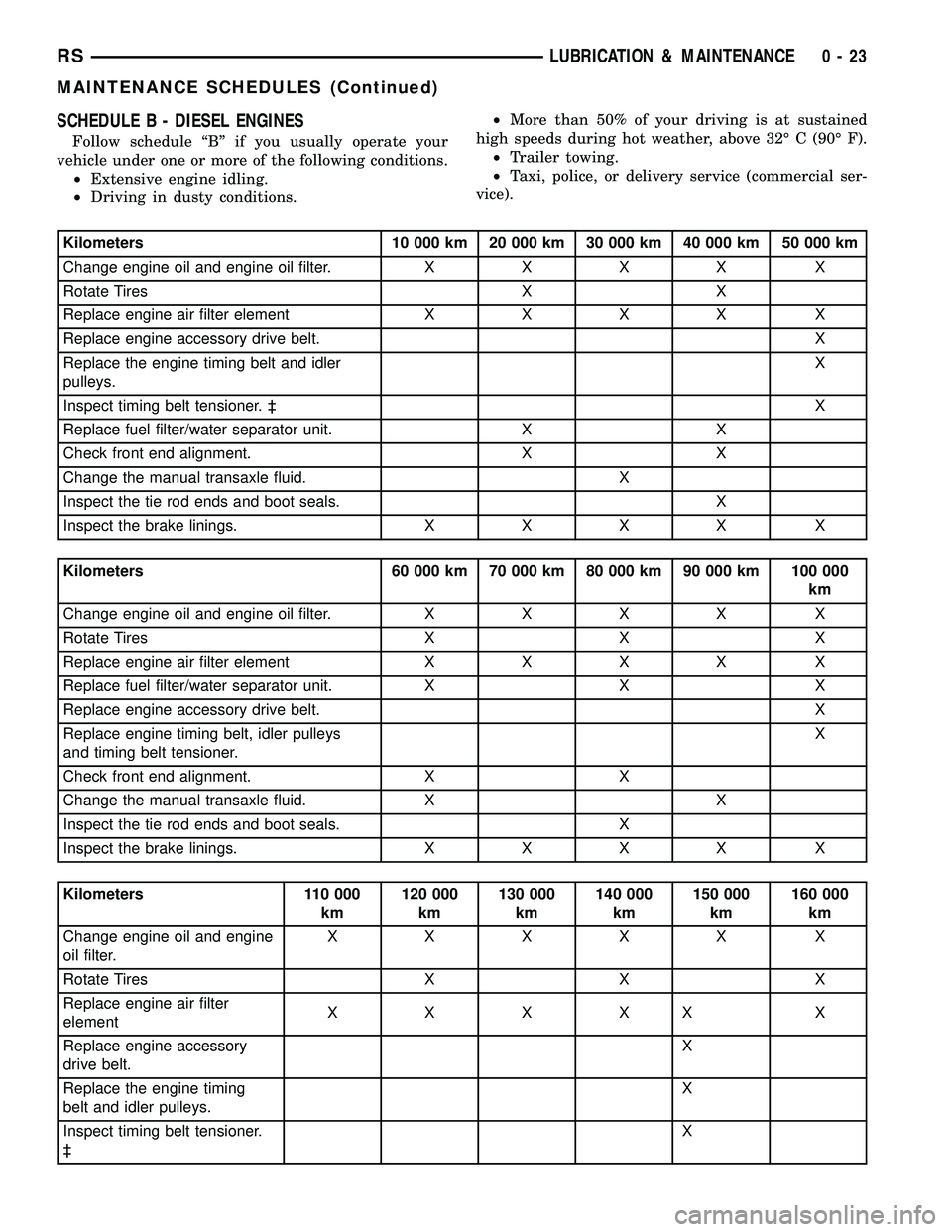
SCHEDULE B - DIESEL ENGINES
Follow schedule ªBº if you usually operate your
vehicle under one or more of the following conditions.
²Extensive engine idling.
²Driving in dusty conditions.²More than 50% of your driving is at sustained
high speeds during hot weather, above 32É C (90É F).
²Trailer towing.
²Taxi, police, or delivery service (commercial ser-
vice).
Kilometers 10 000 km 20 000 km 30 000 km 40 000 km 50 000 km
Change engine oil and engine oil filter.XXXX X
Rotate Tires X X
Replace engine air filter elementXXXX X
Replace engine accessory drive belt. X
Replace the engine timing belt and idler
pulleys.X
Inspect timing belt tensioner. ³X
Replace fuel filter/water separator unit. X X
Check front end alignment. X X
Change the manual transaxle fluid. X
Inspect the tie rod ends and boot seals. X
Inspect the brake linings.XXXX X
Kilometers 60 000 km 70 000 km 80 000 km 90 000 km 100 000
km
Change engine oil and engine oil filter.XXXX X
Rotate Tires X X X
Replace engine air filter elementXXXX X
Replace fuel filter/water separator unit. X X X
Replace engine accessory drive belt. X
Replace engine timing belt, idler pulleys
and timing belt tensioner.X
Check front end alignment. X X
Change the manual transaxle fluid. X X
Inspect the tie rod ends and boot seals. X
Inspect the brake linings.XXXX X
Kilometers 110 000
km120 000
km130 000
km140 000
km150 000
km160 000
km
Change engine oil and engine
oil filter.XXXXX X
Rotate Tires X X X
Replace engine air filter
elementXXXXX X
Replace engine accessory
drive belt.X
Replace the engine timing
belt and idler pulleys.X
Inspect timing belt tensioner.
³X
RSLUBRICATION & MAINTENANCE0-23
MAINTENANCE SCHEDULES (Continued)
Page 40 of 2339
ground, to increase the ground clearance at the rear
of the vehicle. Install lug nuts on wheel attaching
studs to retain brake drums or rotors.
LOCKED VEHICLE TOWING
When a locked vehicle must be towed with the
front wheels on the ground, use a towing dolly or flat
bed hauler.
FLAT TOWING WITH TOW BAR
²Three speed automatic transaxle vehicles can be
flat towed at speeds not to exceed 40 km/h (25 mph)
for not more than 25 km (15 miles). The steering col-
umn must be unlocked and gear selector in neutral.
²Four speed electronic automatic transaxle vehi-
cles can be flat towed at speeds not to exceed 72
km/h (44 mph) for not more than 160 km (100 miles).
The steering column must be unlocked and gear
selector in neutral.
²AWD models should not be flat towed. For addi-
tional information, refer toRECOMMENDED TOW-
ING EQUIPMENTin this section.
FLAT BED TOWING TIE DOWNS
CAUTION: Do not tie vehicle down by attaching
chains or cables to suspension components or
engine mounts, damage to vehicle can result.
The vehicle can be tied to a flat bed device using
the two pair of front slots on the bottom surface of
the rails, behind the front wheels. The two pair of
rear slots on the bottom of the rail between thebumper extension bolts and on the bottom of the rail
just rearward of the jounce bumper. Vehicles
equipped with a rear sway bar have brackets at this
location.
TOWING ± FRONT WHEEL LIFT
If the vehicle is being towed from the front, when-
ever possible ensure at least 10 inches road clearance
to the tires.
TOWING ± REAR WHEEL LIFT
If a vehicle cannot be towed with the front wheels
lifted, the rear wheels can be lifted provided the fol-
lowing guide lines are observed.
CAUTION: Do not use steering column lock to
secure steering wheel during towing operation.
²On AWD vehicles, all four wheels must be free to
rotate. Use towing dollies at unlifted end of vehicle.
²Unlock steering column and secure steering
wheel in straight ahead position with a clamp device
designed for towing.
²Three speed automatic transaxle vehicles can be
flat towed at speeds not to exceed 40 km/h (25 mph)
for not more than 25 km (15 miles). The steering col-
umn must be unlocked and gear selector in neutral.
²Four speed electronic automatic transaxle vehi-
cles can be flat towed at speeds not to exceed 72
km/h (44 mph) for not more than 160 km (100 miles).
The steering column must be unlocked and gear
selector in neutral.
RSLUBRICATION & MAINTENANCE0-27
TOWING (Continued)
Page 72 of 2339
wheel rotates with the hub which is sensed by the
wheel speed sensor.
DIAGNOSIS AND TESTING - HUB AND
BEARING
The bearing contained in the hub and bearing
assembly will produce noise and vibration when worn
or damaged. The noise will generally change when
the bearings are loaded. A road test of the vehicle is
normally required to determine the location of a
worn or damaged bearing.
Find a smooth level road surface and bring the
vehicle up to a constant speed. When vehicle is at a
constant speed, swerve the vehicle back and forth
from the left and to the right. This will load and
unload the bearings and change the noise level.
When bearing damage is slight, the noise is some-
times noticeable at lower speeds and at other times
is more noticeable at speeds above 105 km/h (65
mph).
REMOVAL
FRONT-WHEEL-DRIVE VEHICLES
(1) Raise vehicle. (Refer to LUBRICATION &
MAINTENANCE/HOISTING - STANDARD PROCE-
DURE)
(2) Remove wheel and tire. (Refer to 22 - TIRES/
WHEELS - REMOVAL)
(3) Remove brake drum or disc brake caliper and
rotor from hub and bearing. (Refer to 5 - BRAKES/
HYDRAULIC/MECHANICAL/DRUM - REMOVAL-
)(Refer to 5 - BRAKES/HYDRAULIC/MECHANICAL/
ROTOR - REMOVAL)
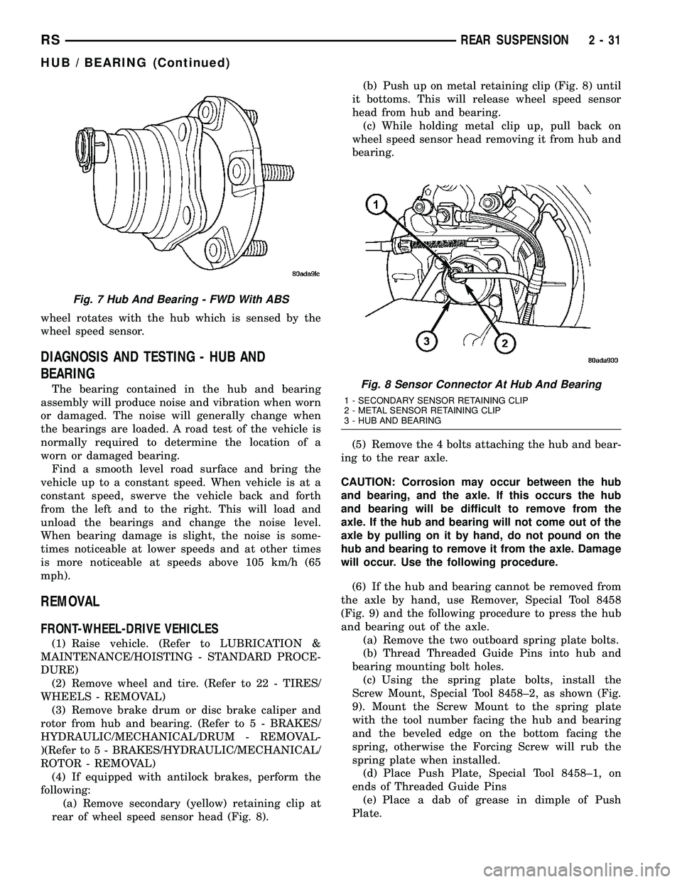
(4) If equipped with antilock brakes, perform the
following:
(a) Remove secondary (yellow) retaining clip at
rear of wheel speed sensor head (Fig. 8).(b) Push up on metal retaining clip (Fig. 8) until
it bottoms. This will release wheel speed sensor
head from hub and bearing.
(c) While holding metal clip up, pull back on
wheel speed sensor head removing it from hub and
bearing.
(5) Remove the 4 bolts attaching the hub and bear-
ing to the rear axle.
CAUTION: Corrosion may occur between the hub
and bearing, and the axle. If this occurs the hub
and bearing will be difficult to remove from the
axle. If the hub and bearing will not come out of the
axle by pulling on it by hand, do not pound on the
hub and bearing to remove it from the axle. Damage
will occur. Use the following procedure.
(6) If the hub and bearing cannot be removed from
the axle by hand, use Remover, Special Tool 8458
(Fig. 9) and the following procedure to press the hub
and bearing out of the axle.
(a) Remove the two outboard spring plate bolts.
(b) Thread Threaded Guide Pins into hub and
bearing mounting bolt holes.
(c) Using the spring plate bolts, install the
Screw Mount, Special Tool 8458±2, as shown (Fig.
9). Mount the Screw Mount to the spring plate
with the tool number facing the hub and bearing
and the beveled edge on the bottom facing the
spring, otherwise the Forcing Screw will rub the
spring plate when installed.
(d) Place Push Plate, Special Tool 8458±1, on
ends of Threaded Guide Pins
(e) Place a dab of grease in dimple of Push
Plate.
Fig. 7 Hub And Bearing - FWD With ABS
Fig. 8 Sensor Connector At Hub And Bearing
1 - SECONDARY SENSOR RETAINING CLIP
2 - METAL SENSOR RETAINING CLIP
3 - HUB AND BEARING
RSREAR SUSPENSION2-31
HUB / BEARING (Continued)
Page 73 of 2339
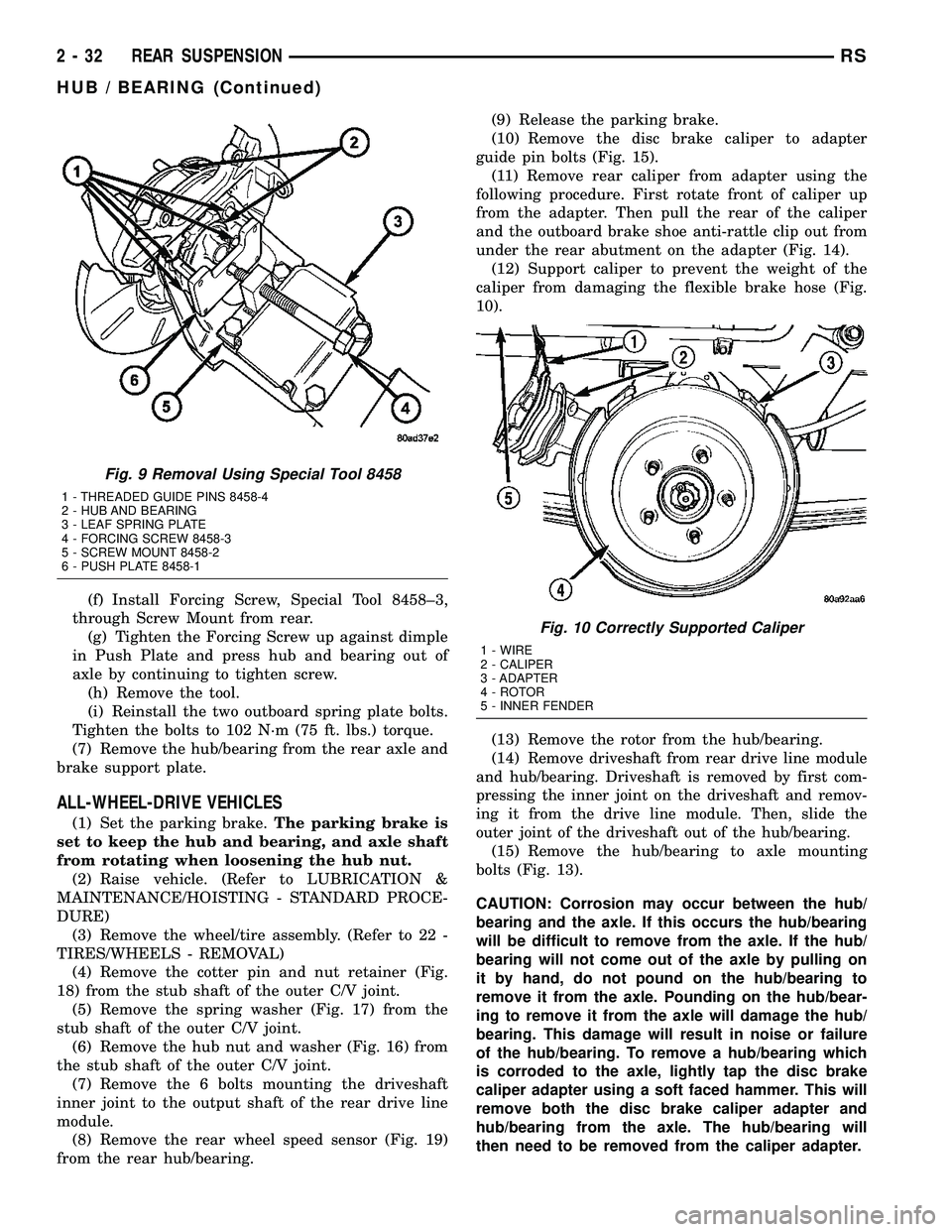
(f) Install Forcing Screw, Special Tool 8458±3,
through Screw Mount from rear.
(g) Tighten the Forcing Screw up against dimple
in Push Plate and press hub and bearing out of
axle by continuing to tighten screw.
(h) Remove the tool.
(i) Reinstall the two outboard spring plate bolts.
Tighten the bolts to 102 N´m (75 ft. lbs.) torque.
(7) Remove the hub/bearing from the rear axle and
brake support plate.
ALL-WHEEL-DRIVE VEHICLES
(1) Set the parking brake.The parking brake is
set to keep the hub and bearing, and axle shaft
from rotating when loosening the hub nut.
(2) Raise vehicle. (Refer to LUBRICATION &
MAINTENANCE/HOISTING - STANDARD PROCE-
DURE)
(3) Remove the wheel/tire assembly. (Refer to 22 -
TIRES/WHEELS - REMOVAL)
(4) Remove the cotter pin and nut retainer (Fig.
18) from the stub shaft of the outer C/V joint.
(5) Remove the spring washer (Fig. 17) from the
stub shaft of the outer C/V joint.
(6) Remove the hub nut and washer (Fig. 16) from
the stub shaft of the outer C/V joint.
(7) Remove the 6 bolts mounting the driveshaft
inner joint to the output shaft of the rear drive line
module.
(8) Remove the rear wheel speed sensor (Fig. 19)
from the rear hub/bearing.(9) Release the parking brake.
(10) Remove the disc brake caliper to adapter
guide pin bolts (Fig. 15).
(11) Remove rear caliper from adapter using the
following procedure. First rotate front of caliper up
from the adapter. Then pull the rear of the caliper
and the outboard brake shoe anti-rattle clip out from
under the rear abutment on the adapter (Fig. 14).
(12) Support caliper to prevent the weight of the
caliper from damaging the flexible brake hose (Fig.
10).
(13) Remove the rotor from the hub/bearing.
(14)
Remove driveshaft from rear drive line module
and hub/bearing. Driveshaft is removed by first com-
pressing the inner joint on the driveshaft and remov-
ing it from the drive line module. Then, slide the
outer joint of the driveshaft out of the hub/bearing.
(15) Remove the hub/bearing to axle mounting
bolts (Fig. 13).
CAUTION: Corrosion may occur between the hub/
bearing and the axle. If this occurs the hub/bearing
will be difficult to remove from the axle. If the hub/
bearing will not come out of the axle by pulling on
it by hand, do not pound on the hub/bearing to
remove it from the axle. Pounding on the hub/bear-
ing to remove it from the axle will damage the hub/
bearing. This damage will result in noise or failure
of the hub/bearing. To remove a hub/bearing which
is corroded to the axle, lightly tap the disc brake
caliper adapter using a soft faced hammer. This will
remove both the disc brake caliper adapter and
hub/bearing from the axle. The hub/bearing will
then need to be removed from the caliper adapter.
Fig. 9 Removal Using Special Tool 8458
1 - THREADED GUIDE PINS 8458-4
2 - HUB AND BEARING
3 - LEAF SPRING PLATE
4 - FORCING SCREW 8458-3
5 - SCREW MOUNT 8458-2
6 - PUSH PLATE 8458-1
Fig. 10 Correctly Supported Caliper
1 - WIRE
2 - CALIPER
3 - ADAPTER
4 - ROTOR
5 - INNER FENDER
2 - 32 REAR SUSPENSIONRS
HUB / BEARING (Continued)
Page 74 of 2339
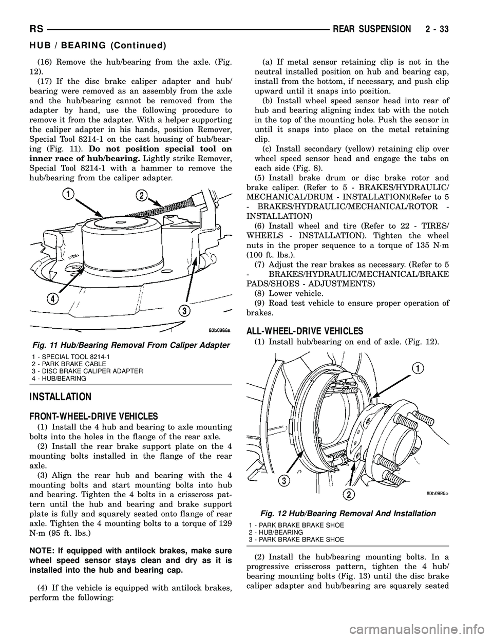
(16) Remove the hub/bearing from the axle. (Fig.
12).
(17) If the disc brake caliper adapter and hub/
bearing were removed as an assembly from the axle
and the hub/bearing cannot be removed from the
adapter by hand, use the following procedure to
remove it from the adapter. With a helper supporting
the caliper adapter in his hands, position Remover,
Special Tool 8214-1 on the cast housing of hub/bear-
ing (Fig. 11).Do not position special tool on
inner race of hub/bearing.Lightly strike Remover,
Special Tool 8214-1 with a hammer to remove the
hub/bearing from the caliper adapter.
INSTALLATION
FRONT-WHEEL-DRIVE VEHICLES
(1) Install the 4 hub and bearing to axle mounting
bolts into the holes in the flange of the rear axle.
(2) Install the rear brake support plate on the 4
mounting bolts installed in the flange of the rear
axle.
(3) Align the rear hub and bearing with the 4
mounting bolts and start mounting bolts into hub
and bearing. Tighten the 4 bolts in a crisscross pat-
tern until the hub and bearing and brake support
plate is fully and squarely seated onto flange of rear
axle. Tighten the 4 mounting bolts to a torque of 129
N´m (95 ft. lbs.)
NOTE: If equipped with antilock brakes, make sure
wheel speed sensor stays clean and dry as it is
installed into the hub and bearing cap.
(4) If the vehicle is equipped with antilock brakes,
perform the following:(a) If metal sensor retaining clip is not in the
neutral installed position on hub and bearing cap,
install from the bottom, if necessary, and push clip
upward until it snaps into position.
(b) Install wheel speed sensor head into rear of
hub and bearing aligning index tab with the notch
in the top of the mounting hole. Push the sensor in
until it snaps into place on the metal retaining
clip.
(c) Install secondary (yellow) retaining clip over
wheel speed sensor head and engage the tabs on
each side (Fig. 8).
(5) Install brake drum or disc brake rotor and
brake caliper. (Refer to 5 - BRAKES/HYDRAULIC/
MECHANICAL/DRUM - INSTALLATION)(Refer to 5
- BRAKES/HYDRAULIC/MECHANICAL/ROTOR -
INSTALLATION)
(6) Install wheel and tire (Refer to 22 - TIRES/
WHEELS - INSTALLATION). Tighten the wheel
nuts in the proper sequence to a torque of 135 N´m
(100 ft. lbs.).
(7) Adjust the rear brakes as necessary. (Refer to 5
- BRAKES/HYDRAULIC/MECHANICAL/BRAKE
PADS/SHOES - ADJUSTMENTS)
(8) Lower vehicle.
(9) Road test vehicle to ensure proper operation of
brakes.
ALL-WHEEL-DRIVE VEHICLES
(1) Install hub/bearing on end of axle. (Fig. 12).
(2) Install the hub/bearing mounting bolts. In a
progressive crisscross pattern, tighten the 4 hub/
bearing mounting bolts (Fig. 13) until the disc brake
caliper adapter and hub/bearing are squarely seatedFig. 11 Hub/Bearing Removal From Caliper Adapter
1 - SPECIAL TOOL 8214-1
2 - PARK BRAKE CABLE
3 - DISC BRAKE CALIPER ADAPTER
4 - HUB/BEARING
Fig. 12 Hub/Bearing Removal And Installation
1 - PARK BRAKE BRAKE SHOE
2 - HUB/BEARING
3 - PARK BRAKE BRAKE SHOE
RSREAR SUSPENSION2-33
HUB / BEARING (Continued)
Page 75 of 2339
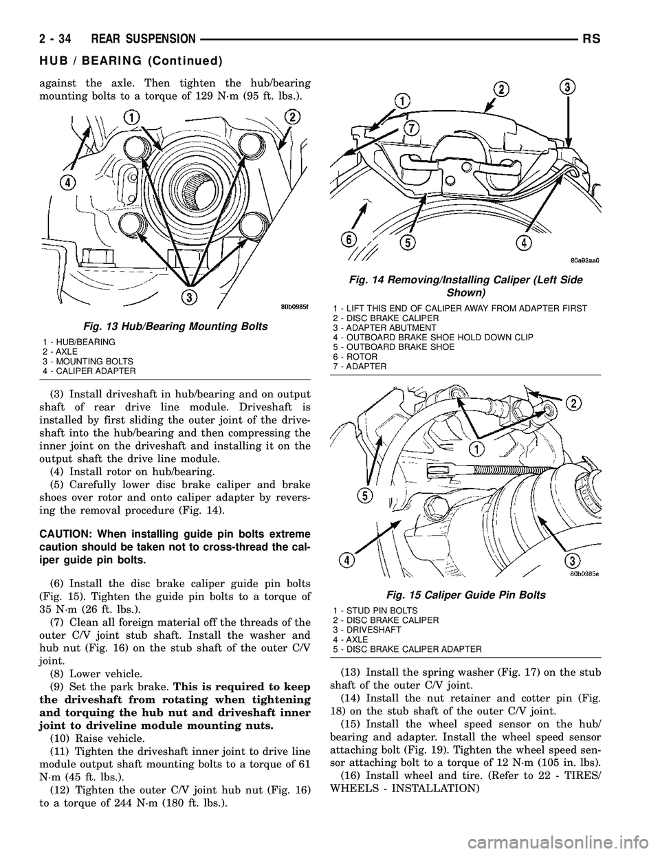
against the axle. Then tighten the hub/bearing
mounting bolts to a torque of 129 N´m (95 ft. lbs.).
(3) Install driveshaft in hub/bearing and on output
shaft of rear drive line module. Driveshaft is
installed by first sliding the outer joint of the drive-
shaft into the hub/bearing and then compressing the
inner joint on the driveshaft and installing it on the
output shaft the drive line module.
(4) Install rotor on hub/bearing.
(5) Carefully lower disc brake caliper and brake
shoes over rotor and onto caliper adapter by revers-
ing the removal procedure (Fig. 14).
CAUTION: When installing guide pin bolts extreme
caution should be taken not to cross-thread the cal-
iper guide pin bolts.
(6) Install the disc brake caliper guide pin bolts
(Fig. 15). Tighten the guide pin bolts to a torque of
35 N´m (26 ft. lbs.).
(7) Clean all foreign material off the threads of the
outer C/V joint stub shaft. Install the washer and
hub nut (Fig. 16) on the stub shaft of the outer C/V
joint.
(8) Lower vehicle.
(9) Set the park brake.This is required to keep
the driveshaft from rotating when tightening
and torquing the hub nut and driveshaft inner
joint to driveline module mounting nuts.
(10) Raise vehicle.
(11) Tighten the driveshaft inner joint to drive line
module output shaft mounting bolts to a torque of 61
N´m (45 ft. lbs.).
(12) Tighten the outer C/V joint hub nut (Fig. 16)
to a torque of 244 N´m (180 ft. lbs.).(13) Install the spring washer (Fig. 17) on the stub
shaft of the outer C/V joint.
(14) Install the nut retainer and cotter pin (Fig.
18) on the stub shaft of the outer C/V joint.
(15) Install the wheel speed sensor on the hub/
bearing and adapter. Install the wheel speed sensor
attaching bolt (Fig. 19). Tighten the wheel speed sen-
sor attaching bolt to a torque of 12 N´m (105 in. lbs).
(16) Install wheel and tire. (Refer to 22 - TIRES/
WHEELS - INSTALLATION)
Fig. 13 Hub/Bearing Mounting Bolts
1 - HUB/BEARING
2 - AXLE
3 - MOUNTING BOLTS
4 - CALIPER ADAPTER
Fig. 14 Removing/Installing Caliper (Left Side
Shown)
1 - LIFT THIS END OF CALIPER AWAY FROM ADAPTER FIRST
2 - DISC BRAKE CALIPER
3 - ADAPTER ABUTMENT
4 - OUTBOARD BRAKE SHOE HOLD DOWN CLIP
5 - OUTBOARD BRAKE SHOE
6 - ROTOR
7 - ADAPTER
Fig. 15 Caliper Guide Pin Bolts
1 - STUD PIN BOLTS
2 - DISC BRAKE CALIPER
3 - DRIVESHAFT
4 - AXLE
5 - DISC BRAKE CALIPER ADAPTER
2 - 34 REAR SUSPENSIONRS
HUB / BEARING (Continued)