width CHRYSLER VOYAGER 2005 User Guide
[x] Cancel search | Manufacturer: CHRYSLER, Model Year: 2005, Model line: VOYAGER, Model: CHRYSLER VOYAGER 2005Pages: 2339, PDF Size: 59.69 MB
Page 1194 of 2339
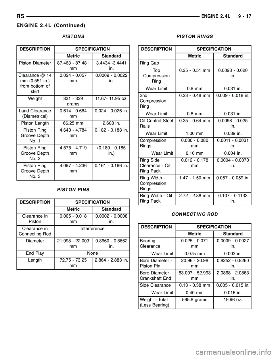
PISTONS
DESCRIPTION SPECIFICATION
Metric Standard
Piston Diameter 87.463 - 87.481
mm3.4434 -3.4441
in.
Clearance @ 14
mm (0.551 in.)
from bottom of
skirt0.024 - 0.057
mm0.0009 - 0.0022
in.
Weight 331 - 339
grams11.67- 11.95 oz.
Land Clearance
(Diametrical)0.614 - 0.664
mm0.024 - 0.026 in.
Piston Length 66.25 mm 2.608 in.
Piston Ring
Groove Depth
No. 14.640 - 4.784
mm0.182 - 0.188 in.
Piston Ring
Groove Depth
No. 24.575 - 4.719
mm(0.180 - 0.185
in.)
Piston Ring
Groove Depth
No. 34.097 - 4.236
mm0.161 - 0.166 in.
PISTON PINS
DESCRIPTION SPECIFICATION
Metric Standard
Clearance in
Piston0.005 - 0.018
mm0.0002 - 0.0008
in.
Clearance in
Connecting RodInterference
Diameter 21.998 - 22.003
mm0.8660 - 0.8662
in.
End Play None
Length 72.75 - 73.25
mm2.864 - 2.883 in.
PISTON RINGS
DESCRIPTION SPECIFICATION
Metric Standard
Ring Gap
To p
Compression
Ring0.25 - 0.51 mm 0.0098 - 0.020
in.
Wear Limit 0.8 mm 0.031 in.
2nd
Compression
Ring0.23 - 0.48 mm 0.009 - 0.018 in.
Wear Limit 0.8 mm 0.031 in.
Oil Control Steel
Rails0.25 - 0.64 mm 0.0098 - 0.025
in.
Wear Limit 1.00 mm 0.039 in.
Compression
Rings0.030 - 0.080
mm0.0011 - 0.0031
in.
Wear Limit 0.10 mm 0.004 in.
Ring Side
Clearance - Oil
Ring Pack0.012 - 0.178
mm0.0004 - 0.0070
in.
Ring Width -
Compression
Rings1.47 - 1.50 mm 0.057 - 0.059 in.
Ring Width - Oil
Ring Pack2.72 - 2.88 mm 0.107 - 0.1133
in.
CONNECTING ROD
DESCRIPTION SPECIFICATION
Metric Standard
Bearing
Clearance0.025 - 0.071
mm0.0009 - 0.0027
in.
Wear Limit 0.075 mm 0.003 in.
Bore Diameter -
Piston Pin20.96 - 20.98
mm0.8252 - 0.8260
in.
Bore Diameter -
Crankshaft End53.007 - 52.993
mm2.0868 - 2.0863
in.
Side Clearance 0.13 - 0.38 mm 0.005 - 0.015 in.
Wear Limit 0.40 mm 0.016 in.
Weight - Total
(Less Bearing)565.8 grams 19.96 oz.
RSENGINE 2.4L9-17
ENGINE 2.4L (Continued)
Page 1196 of 2339
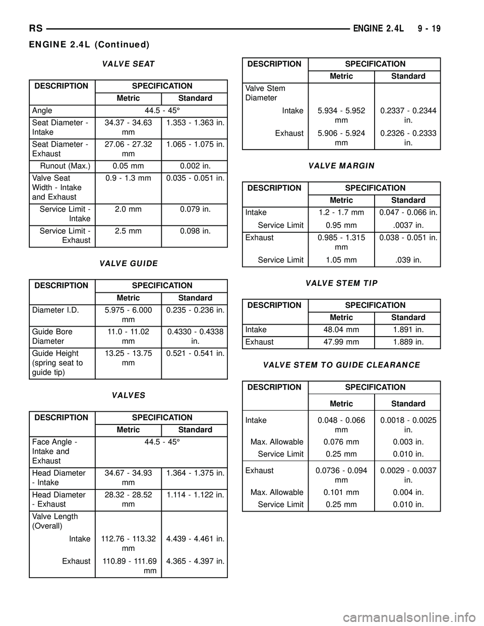
VALVE SEAT
DESCRIPTION SPECIFICATION
Metric Standard
Angle 44.5 - 45É
Seat Diameter -
Intake34.37 - 34.63
mm1.353 - 1.363 in.
Seat Diameter -
Exhaust27.06 - 27.32
mm1.065 - 1.075 in.
Runout (Max.) 0.05 mm 0.002 in.
Valve Seat
Width - Intake
and Exhaust0.9 - 1.3 mm 0.035 - 0.051 in.
Service Limit -
Intake2.0 mm 0.079 in.
Service Limit -
Exhaust2.5 mm 0.098 in.
VALVE GUIDE
DESCRIPTION SPECIFICATION
Metric Standard
Diameter I.D. 5.975 - 6.000
mm0.235 - 0.236 in.
Guide Bore
Diameter11.0 - 11.02
mm0.4330 - 0.4338
in.
Guide Height
(spring seat to
guide tip)13.25 - 13.75
mm0.521 - 0.541 in.
VALVES
DESCRIPTION SPECIFICATION
Metric Standard
Face Angle -
Intake and
Exhaust44.5 - 45É
Head Diameter
- Intake34.67 - 34.93
mm1.364 - 1.375 in.
Head Diameter
- Exhaust28.32 - 28.52
mm1.114 - 1.122 in.
Valve Length
(Overall)
Intake 112.76 - 113.32
mm4.439 - 4.461 in.
Exhaust 110.89 - 111.69
mm4.365 - 4.397 in.
DESCRIPTION SPECIFICATION
Metric Standard
Valve Stem
Diameter
Intake 5.934 - 5.952
mm0.2337 - 0.2344
in.
Exhaust 5.906 - 5.924
mm0.2326 - 0.2333
in.
VALVE MARGIN
DESCRIPTION SPECIFICATION
Metric Standard
Intake 1.2 - 1.7 mm 0.047 - 0.066 in.
Service Limit 0.95 mm .0037 in.
Exhaust 0.985 - 1.315
mm0.038 - 0.051 in.
Service Limit 1.05 mm .039 in.
VALVE STEM TIP
DESCRIPTION SPECIFICATION
Metric Standard
Intake 48.04 mm 1.891 in.
Exhaust 47.99 mm 1.889 in.
VALVE STEM TO GUIDE CLEARANCE
DESCRIPTION SPECIFICATION
Metric Standard
Intake 0.048 - 0.066
mm0.0018 - 0.0025
in.
Max. Allowable 0.076 mm 0.003 in.
Service Limit 0.25 mm 0.010 in.
Exhaust 0.0736 - 0.094
mm0.0029 - 0.0037
in.
Max. Allowable 0.101 mm 0.004 in.
Service Limit 0.25 mm 0.010 in.
RSENGINE 2.4L9-19
ENGINE 2.4L (Continued)
Page 1261 of 2339
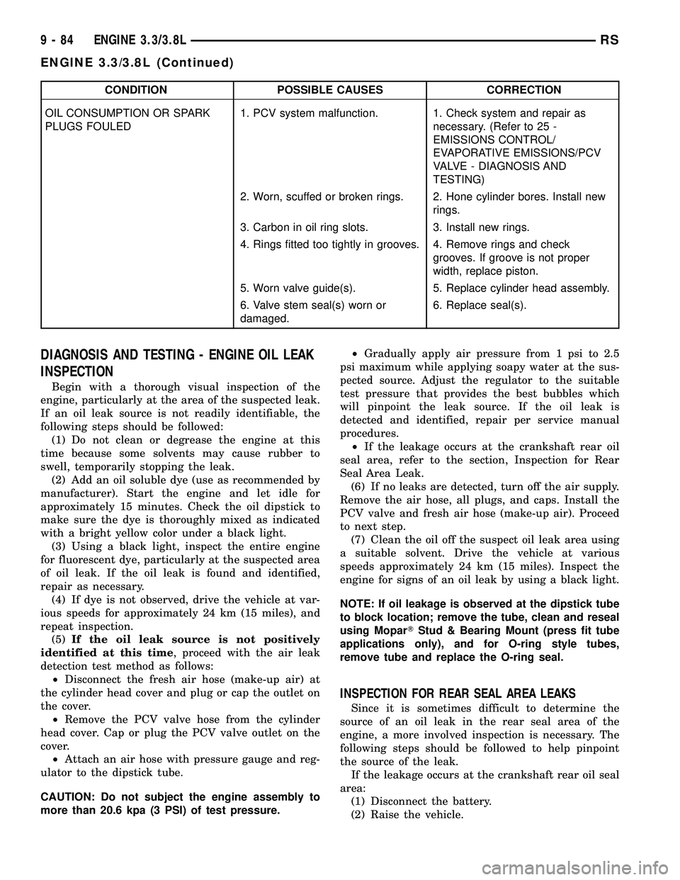
CONDITION POSSIBLE CAUSES CORRECTION
OIL CONSUMPTION OR SPARK
PLUGS FOULED1. PCV system malfunction. 1. Check system and repair as
necessary. (Refer to 25 -
EMISSIONS CONTROL/
EVAPORATIVE EMISSIONS/PCV
VALVE - DIAGNOSIS AND
TESTING)
2. Worn, scuffed or broken rings. 2. Hone cylinder bores. Install new
rings.
3. Carbon in oil ring slots. 3. Install new rings.
4. Rings fitted too tightly in grooves. 4. Remove rings and check
grooves. If groove is not proper
width, replace piston.
5. Worn valve guide(s). 5. Replace cylinder head assembly.
6. Valve stem seal(s) worn or
damaged.6. Replace seal(s).
DIAGNOSIS AND TESTING - ENGINE OIL LEAK
INSPECTION
Begin with a thorough visual inspection of the
engine, particularly at the area of the suspected leak.
If an oil leak source is not readily identifiable, the
following steps should be followed:
(1) Do not clean or degrease the engine at this
time because some solvents may cause rubber to
swell, temporarily stopping the leak.
(2) Add an oil soluble dye (use as recommended by
manufacturer). Start the engine and let idle for
approximately 15 minutes. Check the oil dipstick to
make sure the dye is thoroughly mixed as indicated
with a bright yellow color under a black light.
(3) Using a black light, inspect the entire engine
for fluorescent dye, particularly at the suspected area
of oil leak. If the oil leak is found and identified,
repair as necessary.
(4) If dye is not observed, drive the vehicle at var-
ious speeds for approximately 24 km (15 miles), and
repeat inspection.
(5)If the oil leak source is not positively
identified at this time, proceed with the air leak
detection test method as follows:
²Disconnect the fresh air hose (make-up air) at
the cylinder head cover and plug or cap the outlet on
the cover.
²Remove the PCV valve hose from the cylinder
head cover. Cap or plug the PCV valve outlet on the
cover.
²Attach an air hose with pressure gauge and reg-
ulator to the dipstick tube.
CAUTION: Do not subject the engine assembly to
more than 20.6 kpa (3 PSI) of test pressure.²Gradually apply air pressure from 1 psi to 2.5
psi maximum while applying soapy water at the sus-
pected source. Adjust the regulator to the suitable
test pressure that provides the best bubbles which
will pinpoint the leak source. If the oil leak is
detected and identified, repair per service manual
procedures.
²If the leakage occurs at the crankshaft rear oil
seal area, refer to the section, Inspection for Rear
Seal Area Leak.
(6) If no leaks are detected, turn off the air supply.
Remove the air hose, all plugs, and caps. Install the
PCV valve and fresh air hose (make-up air). Proceed
to next step.
(7) Clean the oil off the suspect oil leak area using
a suitable solvent. Drive the vehicle at various
speeds approximately 24 km (15 miles). Inspect the
engine for signs of an oil leak by using a black light.
NOTE: If oil leakage is observed at the dipstick tube
to block location; remove the tube, clean and reseal
using MoparTStud & Bearing Mount (press fit tube
applications only), and for O-ring style tubes,
remove tube and replace the O-ring seal.
INSPECTION FOR REAR SEAL AREA LEAKS
Since it is sometimes difficult to determine the
source of an oil leak in the rear seal area of the
engine, a more involved inspection is necessary. The
following steps should be followed to help pinpoint
the source of the leak.
If the leakage occurs at the crankshaft rear oil seal
area:
(1) Disconnect the battery.
(2) Raise the vehicle.
9 - 84 ENGINE 3.3/3.8LRS
ENGINE 3.3/3.8L (Continued)
Page 1263 of 2339

Calibrate the tester according to the manufactur-
er's instructions. The shop air source for testing
should maintain 483 kPa (70 psi) minimum, 1,379
kPa (200 psi) maximum, with 552 kPa (80 psi) rec-
ommended.
Perform the test procedures on each cylinder
according to the tester manufacturer's instructions.
While testing, listen for pressurized air escaping
through the throttle body, tailpipe and oil filler cap
opening. Check for bubbles in the coolant.
All gauge pressure indications should be equal,
with no more than 25% leakage per cylinder.
FOR EXAMPLE:At 552 kPa (80 psi) input pres-
sure, a minimum of 414 kPa (60 psi) should be main-
tained in the cylinder.
STANDARD PROCEDURE
STANDARD PROCEDURE - MEASURING
BEARING CLEARANCE USING PLASTIGAGE
Engine crankshaft bearing clearances can be deter-
mined by use of Plastigage or equivalent. The follow-
ing is the recommended procedure for the use of
Plastigage:
(1) Remove oil film from surface to be checked.
Plastigage is soluble in oil.
(2) Place a piece of Plastigage across the entire
width of the bearing shell in the cap approximately
6.35 mm (1/4 in.) off center and away from the oil
holes (Fig. 3). (In addition, suspected areas can be
checked by placing the Plastigage in the suspected
area). Torque the bearing cap/bed plate bolts of the
bearing being checked to the proper specifications.
(3) Remove the bearing cap and compare the
width of the flattened Plastigage with the metric
scale provided on the package. Locate the band clos-est to the same width. This band shows the amount
of clearance in thousandths of a millimeter. Differ-
ences in readings between the ends indicate the
amount of taper present. Record all readings taken.
Compare the clearance measurements to specsifica-
tions found in the engine specifications table(Refer to
9 - ENGINE - SPECIFICATIONS).Plastigage gen-
erally is accompanied by two scales. One scale
is in inches, the other is a metric scale.
NOTE: Plastigage is available in a variety of clear-
ance ranges. Use the most appropriate range for
the specifications you are checking.
(4) Install the proper crankshaft bearings to
achieve the specified bearing clearances.
FORM-IN-PLACE GASKETS AND SEALERS
There are numerous places where form-in-place
gaskets are used on the engine. Care must be taken
when applying form-in-place gaskets to assure
obtaining the desired results.Do not use form-in-
place gasket material unless specified.Bead size,
continuity, and location are of great importance. Too
thin a bead can result in leakage while too much can
result in spill-over which can break off and obstruct
fluid feed lines. A continuous bead of the proper
width is essential to obtain a leak-free gasket.
There are numerous types of form-in-place gasket
materials that are used in the engine area. Mopart
Engine RTV GEN II, MopartATF-RTV, and Mopart
Gasket Maker gasket materials, each have different
properties and can not be used in place of the other.
MOPARtENGINE RTV GEN IIis used to seal
components exposed to engine oil. This material is a
specially designed black silicone rubber RTV that
retains adhesion and sealing properties when
exposed to engine oil. Moisture in the air causes the
material to cure. This material is available in three
ounce tubes and has a shelf life of one year. After one
year this material will not properly cure. Always
inspect the package for the expiration date before
use.
MOPARtATF RTVis a specifically designed
black silicone rubber RTV that retains adhesion and
sealing properties to seal components exposed to
automatic transmission fluid, engine coolants, and
moisture. This material is available in three ounce
tubes and has a shelf life of one year. After one year
this material will not properly cure. Always inspect
the package for the expiration date before use.
MOPARtGASKET MAKERis an anaerobic type
gasket material. The material cures in the absence of
air when squeezed between two metallic surfaces. It
will not cure if left in the uncovered tube. The
anaerobic material is for use between two machined
surfaces. Do not use on flexible metal flanges.
Fig. 3 Plastigage Placed in Lower ShellÐTypical
1 - PLASTIGAGE
9 - 86 ENGINE 3.3/3.8LRS
ENGINE 3.3/3.8L (Continued)
Page 1271 of 2339

CONNECTING RODS
DESCRIPTION SPECIFICATION
Metric Standard
Bearing
Clearance0.019-0.065
mm.0.017-0.020 in.
Wear Limit 0.074 mm 0.003 in.
Side Clearance 0.13-0.32 mm 0.005-0.013 in.
Wear Limit 0.38 mm 0.015 in.
PISTONS
DESCRIPTION SPECIFICATION
Metric Standard
Piston Diameter
3.3L-Measured
39.8 mm (1.567
in) From Piston
To p92.968-92.998
mm.3.660-3.661 in.
Piston Diameter
3.8L-Measured
33.01 mm (1.30
in) From Piston
To p95.968-95.998
mm.3.778-3.779 in.
Clearance in
Bore @ Size
Location (New)-0.005-0.039
mm-0.0002±0.0015
in.
Weight 3.3L 362 5 grams 12.77 0.1764
oz.
Weight 3.8L 426 5 grams 15.03 0.1764
oz.
PISTON PINS
DESCRIPTION SPECIFICATION
Metric Standard
Type Press Fit in Rod (Serviced as a
Assembly)
Clearance in
Piston @ 21C
(70ÉF)0.006-0.019
mm0.0002-0.0007
in.
Clearance in
Connecting RodInterference Fit
Diameter 22.87-22.88
mm0.9007-0.9009
in.
Length 3.3L 67.25-67.75
mm2.648-2.667 in.
Length 3.8L 71.25-71.75
mm2.805-2.824 in.
PISTON RINGS
DESCRIPTION SPECIFICATION
Metric Standard
Ring End Gap
To p
Compression
Ring0.18-0.38 mm 0.007-0.015 in.
Second
Compression
Ring0.28-0.57 mm 0.011-0.022 in.
Oil Control
(Steel Rails)0.23-0.78 mm 0.009-0.030 in.
Wear Limit-
Compression
Rings1.0 mm 0.039 in.
Wear Limit-Oil
Control Steel
Rails1.88 mm 0.074 in.
Ring Side
Clearance
To p
Compression
Ring 3.3L0.030-0.080
mm0.0012-0.0031
in.
To p
Compression
Ring 3.8L0.030-0.069
mm0.0012-0.0027
in.
Second
Compression
Ring 3.3L0.030-0.095
mm0.0012-0.0037
in.
Second
Compression
Ring 3.8L0.041-0.085
mm0.0016-0.0033
in.
Oil Ring (Steel
Ring)0.039-0.200
mm0.0015-0.0078
in.
Wear Limit- Top
Ring0.10 mm 0.004 in.
Wear Limit-2nd
Ring0.13 mm 0.005
Wear Limit Oil
Ring Pack0.266 mm 0.009
Ring Width-Top
Compression
Ring 3.3L1.46-1.49 mm 0.0575-0.058 in.
Ring Width-Top
Compression
Ring 3.8L1.175-1.190
mm0.0462-0.0468
9 - 94 ENGINE 3.3/3.8LRS
ENGINE 3.3/3.8L (Continued)
Page 1272 of 2339

DESCRIPTION SPECIFICATION
Metric Standard
Ring Width-2nd
Compression
Ring 3.3L and
3.8L1.46-1.49 mm 0.0575-0.058 in.
Ring Width-Oil
Ring (Steel
Rails) 3.3L0.435-0.490
mm-.017-0.019 in.
Ring Width-Oil
Ring (Steel
Rails) 3.8L0.435-0.510
mm0.017-0.020
CAMSHAFT
DESCRIPTION SPECIFICATION
Metric Standard
Journal
Diameter
#1 50.724-50.775
mm1.997-1.999 in.
#2 50.317-50.368
mm1.9809-1.9829
in.
#3 49.936-49.987
mm1.9659-1.9679
in.
#4 49.530-49.581
mm1.9499-1.9520
in.
Bearing
Clearance-
Diametrical0.025-0.101
mm0.001-0.004 in.
Bearing
Clearance
(Max.Allowable)0.127 mm 0.005 in.
End Play 0.254-0.508
mm0.010-0.020 in.
Camshaft
Bearing
Diameter
#1 50.800-50.825 1.9999-2.0009
in.
#2 50.393-50.419
mm1.9839-1.9849
in.
#3 50.013-50.038
mm1.9690-1.9699
in.
#4 49.606-49.632
mm1.9529-1.954 in.
Exhaust Valve
Timing
Closes-3.3L
(ATDC)- 13É
Closes-3.8L
(ATDC)- 18É
Opens-3.3L
(BBDC)- 43É
Opens-3.8L
(BBDC)- 46É
Duration-3.3L - 236É
Duration-3.8L - 244É
Intake Valve
Timing
Closes-3.3L
(ABDC)- 52É
Closes-3.8L
(ABDC)- 63É
Opens-3.3L
(ATDC)-6É
Opens-3.8L
(ATDC)-1É
Duration-3.3L - 226É
Duration-3.8L - 242É
Valve Overlap-
3.3L-7É
Valve Overlap-
3.8L- 17É
HYDRAULIC LIFTER
DESCRIPTION SPECIFICATION
Metric Standard
Type Hydraulic Roller
Outside
Diameter22.949-22.962
mm0.903-0.904 in.
Clearance in
Block0.020-0.061
mm0.0007-0.0024
in.
CYLINDER HEAD
DESCRIPTION SPECIFICATION
Metric Standard
Gasket
Thickness
(Compressed)0.65-0.75 mm 0.0007-0.0024
in.
RSENGINE 3.3/3.8L9-95
ENGINE 3.3/3.8L (Continued)
Page 1273 of 2339

VALVES
DESCRIPTION SPECIFICATION
Metric Standard
Face Angle-
Intake- 45-45.5É
Face Angle-
Exhaust- 45-45.5É
Head Diameter-
Intake47.87-48.13
mm1.88-1.89 in.
Head Diameter-
Exhaust35.37-35.63
mm1.39-1.40 in.
Valve Lift (Zero
Lash)-Intake
and Exhaust-
3.3L9.80 mm 0.385 in.
Valve Lift (Zero
Lash)-Intake
and Exhaust-
3.8L11.0 mm 0.433 in.
Valve Length-
Intake125.84-126.6
mm4.95-4.98 in.
Valve Length-
Exhaust127.20-127.96 5.00-5.04 in.
Valve Stem to
Tip Height
(valve tip to
spring seat
washer)-Intake48.1-49.7 mm 1.89-1.95 in.
Valve Stem to
Tip Height
(valve tip to
spring seat
washer)-
Exhaust48.53-50.09
mm1.91-1.97 in.
VALVE SEAT
DESCRIPTION SPECIFICATION
Metric Standard
Angle - 44.5-45É
Run Out
(Service Limits)0.0762 mm 0.003 in.
Width-Intake
and Exhaust1.50-2.00 mm 0.057-0.078 in.
VALVE GUIDE
DESCRIPTION SPECIFICATION
Metric Standard
Guide Bore
Diameter (Std.)6.975-7.00 mm 0.274-0.275 in.
VALVE MARGIN
DESCRIPTION SPECIFICATION
Metric Standard
Intake 0.825-0.973
mm0.032-0.038 in.
Exhaust 1.565-1.713
mm0.061-0.067 in.
VALVE STEM DIAMETER
DESCRIPTION SPECIFICATION
Metric Standard
Intake
(Standard)6.935-6.953
mm0.2718-0.2725
in.
Exhaust
(Standard)6.906-6.924
mm0.2718-0.2725
in.
VALVE STEM TO GUIDE CLEARANCE
DESCRIPTION SPECIFICATION
Metric Standard
Intake 0.025-0.065
mm0.001-0.0025 in.
Exhaust 0.059-0.094
mm0.002-0.0037 in.
Max Allowable-
Intake (Rocking
Method)0.247 mm 0.010 in.
Max Allowable-
Exhaust
(Rocking
Method)0.414 mm 0.016 in.
PUSH RODS
DESCRIPTION SPECIFICATION
Metric Standard
Length 135.438 mm 5.33 in.
9 - 96 ENGINE 3.3/3.8LRS
ENGINE 3.3/3.8L (Continued)
Page 1284 of 2339
CYLINDER HEAD COVER -
LEFT
REMOVAL
(1) Disconnect spark plug wires from spark plugs.
(2) Disconnect crankcase vent hose from cylinder
head cover.
(3) Remove cylinder head cover bolts.
(4) Remove cylinder head cover and gasket.
INSTALLATION
(1) Clean cylinder head and cover mating surfaces.
Inspect cylinder head cover surface for flatness.
Replace gasket as necessary.
(2) Assemble gasket to cylinder cover by inserting
the fasteners through each bolt hole on cover and
gasket (Fig. 25).
(3) Install the cylinder head cover and bolts (Fig.
26).
(4) Tighten cylinder head cover bolts to 12 N´m
(105 in. lbs.) (Fig. 26).
(5) Connect crankcase vent hose.
(6) Connect spark plug wires to spark plugs.
INTAKE/EXHAUST VALVES &
SEATS
DESCRIPTION
The valves have chrome plated valve stems with
four-bead lock grooves. The valve stem seals are
made of Viton rubber.
OPERATION
The two valves per cylinder are opened using
hydraulic lifters, push rods, and rocker arms.
STANDARD PROCEDURE - REFACING VALVES
AND VALVE SEATS
The intake and exhaust valves and seats are
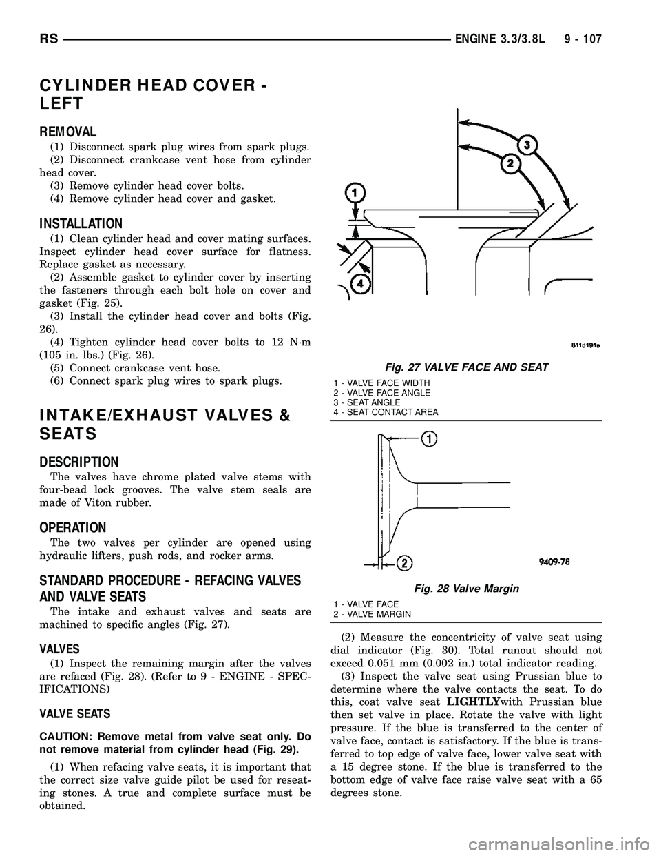
machined to specific angles (Fig. 27).
VALVES
(1) Inspect the remaining margin after the valves
are refaced (Fig. 28). (Refer to 9 - ENGINE - SPEC-
IFICATIONS)
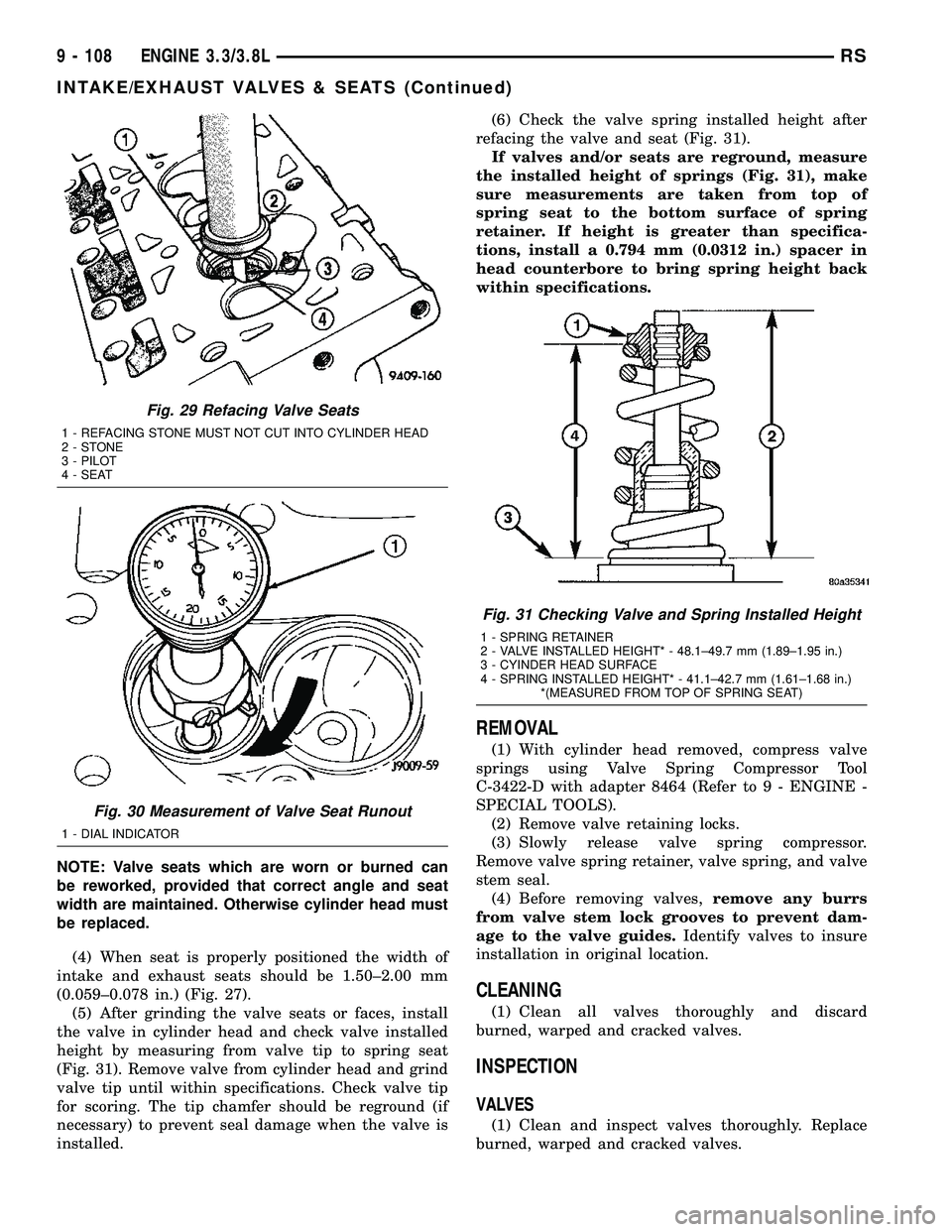
VALVE SEATS
CAUTION: Remove metal from valve seat only. Do
not remove material from cylinder head (Fig. 29).
(1) When refacing valve seats, it is important that
the correct size valve guide pilot be used for reseat-
ing stones. A true and complete surface must be
obtained.(2) Measure the concentricity of valve seat using
dial indicator (Fig. 30). Total runout should not
exceed 0.051 mm (0.002 in.) total indicator reading.
(3) Inspect the valve seat using Prussian blue to
determine where the valve contacts the seat. To do
this, coat valve seatLIGHTLYwith Prussian blue
then set valve in place. Rotate the valve with light
pressure. If the blue is transferred to the center of
valve face, contact is satisfactory. If the blue is trans-
ferred to top edge of valve face, lower valve seat with
a 15 degree stone. If the blue is transferred to the
bottom edge of valve face raise valve seat with a 65
degrees stone.
Fig. 27 VALVE FACE AND SEAT
1 - VALVE FACE WIDTH
2 - VALVE FACE ANGLE
3 - SEAT ANGLE
4 - SEAT CONTACT AREA
Fig. 28 Valve Margin
1 - VALVE FACE
2 - VALVE MARGIN
RSENGINE 3.3/3.8L9 - 107
Page 1285 of 2339
NOTE: Valve seats which are worn or burned can
be reworked, provided that correct angle and seat
width are maintained. Otherwise cylinder head must
be replaced.
(4) When seat is properly positioned the width of
intake and exhaust seats should be 1.50±2.00 mm
(0.059±0.078 in.) (Fig. 27).
(5) After grinding the valve seats or faces, install
the valve in cylinder head and check valve installed
height by measuring from valve tip to spring seat
(Fig. 31). Remove valve from cylinder head and grind
valve tip until within specifications. Check valve tip
for scoring. The tip chamfer should be reground (if
necessary) to prevent seal damage when the valve is
installed.(6) Check the valve spring installed height after
refacing the valve and seat (Fig. 31).
If valves and/or seats are reground, measure
the installed height of springs (Fig. 31), make
sure measurements are taken from top of
spring seat to the bottom surface of spring
retainer. If height is greater than specifica-
tions, install a 0.794 mm (0.0312 in.) spacer in
head counterbore to bring spring height back
within specifications.
REMOVAL
(1) With cylinder head removed, compress valve
springs using Valve Spring Compressor Tool
C-3422-D with adapter 8464 (Refer to 9 - ENGINE -
SPECIAL TOOLS).
(2) Remove valve retaining locks.
(3) Slowly release valve spring compressor.
Remove valve spring retainer, valve spring, and valve
stem seal.
(4) Before removing valves,remove any burrs
from valve stem lock grooves to prevent dam-
age to the valve guides.Identify valves to insure
installation in original location.
CLEANING
(1) Clean all valves thoroughly and discard
burned, warped and cracked valves.
INSPECTION
VALVES
(1) Clean and inspect valves thoroughly. Replace
burned, warped and cracked valves.
Fig. 29 Refacing Valve Seats
1 - REFACING STONE MUST NOT CUT INTO CYLINDER HEAD
2-STONE
3 - PILOT
4 - SEAT
Fig. 30 Measurement of Valve Seat Runout
1 - DIAL INDICATOR
Fig. 31 Checking Valve and Spring Installed Height
1 - SPRING RETAINER
2 - VALVE INSTALLED HEIGHT* - 48.1±49.7 mm (1.89±1.95 in.)
3 - CYINDER HEAD SURFACE
4 - SPRING INSTALLED HEIGHT* - 41.1±42.7 mm (1.61±1.68 in.)
*(MEASURED FROM TOP OF SPRING SEAT)
9 - 108 ENGINE 3.3/3.8LRS
INTAKE/EXHAUST VALVES & SEATS (Continued)
Page 1300 of 2339
CONNECTING ROD BEARINGS
STANDARD PROCEDURE - MEASURING
CONNECTING ROD BEARING CLEARANCE
The bearing caps are not interchangeable and
should be marked at removal to ensure correct
assembly. The bearing shells must be installed with
the tangs inserted into the machined grooves in the
rods and caps. Install cap with the tangs on the same
side as the rod. Fit all rods on one bank until com-
plete. Connecting rod bearings are available in the
standard size and the following undersizes: 0.025
mm (0.001 in.) and 0.250 mm (0.010 in.).
CAUTION: Install the bearings in pairs. Do not use a
new bearing half with an old bearing half. Do not
file the rods or bearing caps.
Measure connecting rod journal for taper and out-
of-round. (Refer to 9 - ENGINE/ENGINE BLOCK/
CRANKSHAFT - INSPECTION)The connecting rod bearing clearances can be
determined by use of Plastigage or the equivalent.
The following is the recommended procedure for the
use of Plastigage:
(1) Rotate the crankshaft until the connecting rod
to be checked is at the bottom of its stroke.
(2) Remove oil film from surface to be checked.
Plastigage is soluble in oil.
(3) Place a piece of Plastigage across the entire
width of the bearing shell in the bearing cap approx-
imately 6.35 mm (1/4 in.) off center and away from
the oil hole. In addition, suspect areas can be
checked by placing Plastigage in that area.
(4) Assemble the rod cap with Plastigage in place.
Tighten the rod cap to the specified torque.Do not
rotate the crankshaft while assembling the cap
or the Plastigage may be smeared, giving inac-
curate results.
(5) Remove the bearing cap and compare the
width of the flattened Plastigage with the scale pro-
vided on the package (Fig. 61). Locate the band clos-
est to the same width. This band indicates the
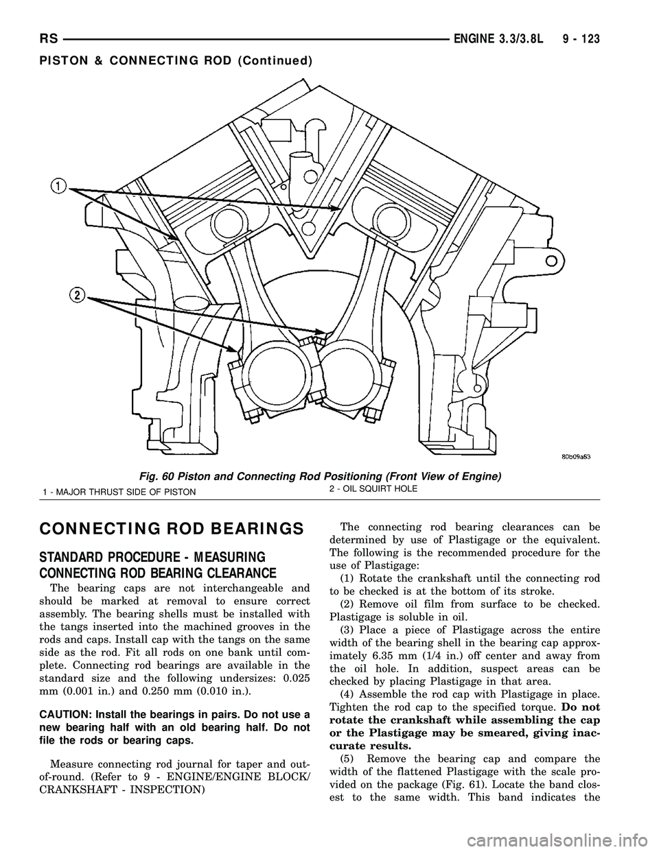
Fig. 60 Piston and Connecting Rod Positioning (Front View of Engine)
1 - MAJOR THRUST SIDE OF PISTON2 - OIL SQUIRT HOLE
RSENGINE 3.3/3.8L9 - 123
PISTON & CONNECTING ROD (Continued)