Rear control CHRYSLER VOYAGER 2005 Service Manual
[x] Cancel search | Manufacturer: CHRYSLER, Model Year: 2005, Model line: VOYAGER, Model: CHRYSLER VOYAGER 2005Pages: 2339, PDF Size: 59.69 MB
Page 2192 of 2339
resulting output drives the power module circuitry,
which adjusts the voltage output received from the
rear blower motor relay to change or maintain the
desired blower speed. The rear blower motor power
module is diagnosed using a DRBIIItscan tool. Refer
to Body Diagnostic Procedures.
REMOVAL
(1) Disconnect and isolate the battery negative
cable.
(2) Remove the right quarter trim panel and right
D-pillar trim panel from the quarter inner panel
(Refer to 23 - BODY/INTERIOR/QUARTER TRIM
PANEL - REMOVAL).
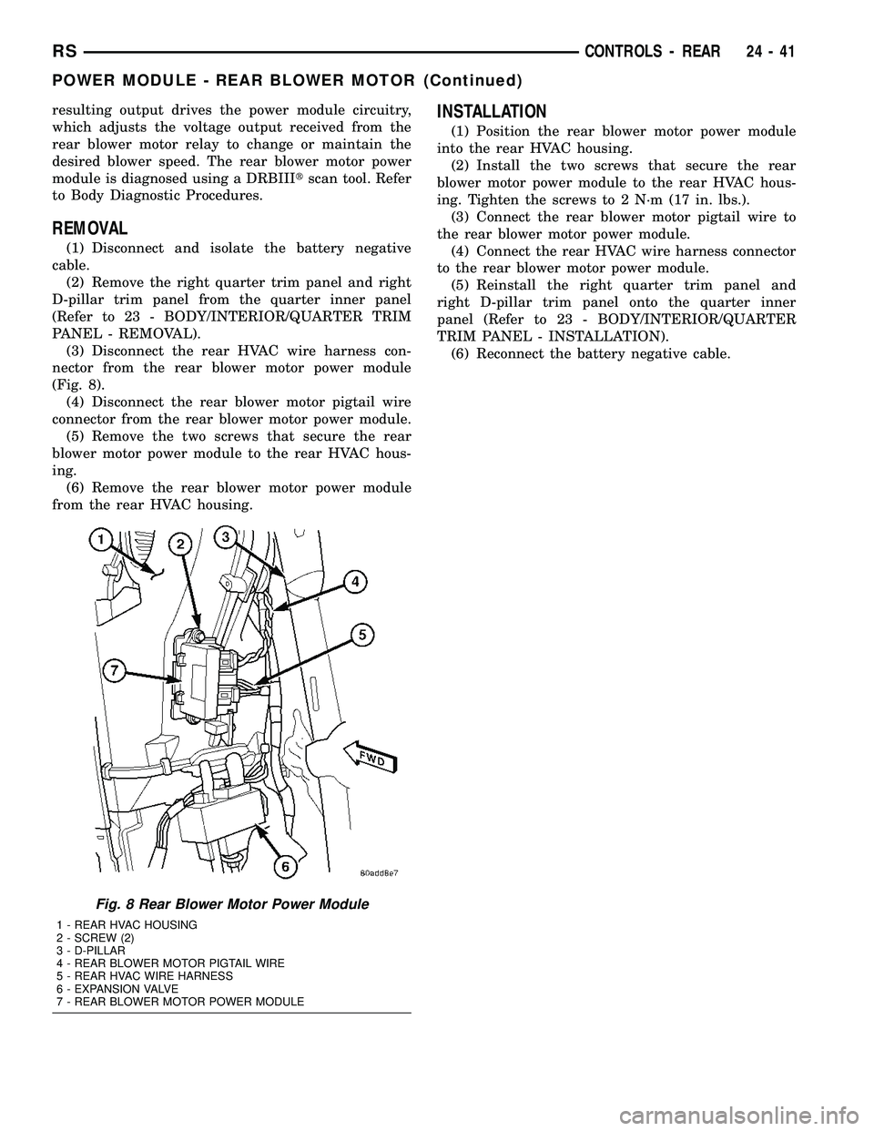
(3) Disconnect the rear HVAC wire harness con-
nector from the rear blower motor power module
(Fig. 8).
(4) Disconnect the rear blower motor pigtail wire
connector from the rear blower motor power module.
(5) Remove the two screws that secure the rear
blower motor power module to the rear HVAC hous-
ing.
(6) Remove the rear blower motor power module
from the rear HVAC housing.
INSTALLATION
(1) Position the rear blower motor power module
into the rear HVAC housing.
(2) Install the two screws that secure the rear
blower motor power module to the rear HVAC hous-
ing. Tighten the screws to 2 N´m (17 in. lbs.).
(3) Connect the rear blower motor pigtail wire to
the rear blower motor power module.
(4) Connect the rear HVAC wire harness connector
to the rear blower motor power module.
(5) Reinstall the right quarter trim panel and
right D-pillar trim panel onto the quarter inner
panel (Refer to 23 - BODY/INTERIOR/QUARTER
TRIM PANEL - INSTALLATION).
(6) Reconnect the battery negative cable.
Fig. 8 Rear Blower Motor Power Module
1 - REAR HVAC HOUSING
2 - SCREW (2)
3 - D-PILLAR
4 - REAR BLOWER MOTOR PIGTAIL WIRE
5 - REAR HVAC WIRE HARNESS
6 - EXPANSION VALVE
7 - REAR BLOWER MOTOR POWER MODULE
RSCONTROLS - REAR24-41
POWER MODULE - REAR BLOWER MOTOR (Continued)
Page 2193 of 2339

DISTRIBUTION - FRONT
TABLE OF CONTENTS
page page
AIR FILTER
DESCRIPTION.........................42
REMOVAL.............................42
INSTALLATION.........................43
AIR OUTLETS
DESCRIPTION.........................43
REMOVAL
FRONT CENTER BEZEL OUTLETS........44
FRONT DEMISTER OUTLETS............44
INSTRUMENT PANEL OUTLETS..........45
INSTALLATION
FRONT CENTER BEZEL OUTLETS........45
FRONT DEMISTER OUTLETS............45
INSTRUMENT PANEL OUTLETS..........45
BLOWER MOTOR
DESCRIPTION.........................45
OPERATION...........................45
DIAGNOSIS AND TESTING
FRONT BLOWER MOTOR...............46
REMOVAL.............................48INSTALLATION.........................49
DEFROSTER DUCT
REMOVAL.............................49
INSTALLATION.........................50
FLOOR DISTRIBUTION DUCTS
REMOVAL.............................50
INSTALLATION.........................50
HVAC HOUSING
REMOVAL
REMOVAL...........................50
DISSASEMBLY.......................51
INSTALLATION
ASSEMBLY..........................53
INSTALLATION.......................53
INSTRUMENT PANEL DEMISTER DUCTS
REMOVAL.............................54
INSTALLATION.........................54
INSTRUMENT PANEL DUCTS
REMOVAL.............................55
INSTALLATION.........................55
AIR FILTER
DESCRIPTION
A dust and odor air filter is standard equipment on
models equipped with the three zone temperature
control systems (Fig. 1). The filter element is the
same size as the front air conditioner evaporator to
ensure ample filtering capacity. A removable door on
the bottom of the front HVAC housing below the
glove box provides easy access to the filter element
for replacement. The filter should be checked and
replaced at least once every 24,000 km (15,000 miles)
and checked if heater-A/C system performance seems
lower than expected.
REMOVAL
(1) Locate the air filter door on the bottom of the
lower HVAC housing just outboard of the passenger
side of the instrument panel center stack (Fig. 2).
(2) Slide the air filter door latch toward the rear of
the vehicle until it engages the opened stop on the
door.Fig. 1 Air Filter - LHD Shown, RHD Typical
1 - LOWER HVAC HOUSING
2 - LOWER EDGE OF INSTRUMENT PANEL
3 - AIR FILTER (IF EQUIPPED)
4 - CENTER FLOOR BRACKET COVER
5 - FILTER SEALING EDGES (IF EQUIPPED)
6 - AIR FILTER OPENING (IF EQUIPPED)
24 - 42 DISTRIBUTION - FRONTRS
Page 2194 of 2339

(3) Pull the air filter door straight downward to
disengage it from the air filter opening of the lower
HVAC housing.
(4) Use your fingers to reach through the air filter
opening of the lower HVAC housing far enough to
grasp the air filter.
(5) Pull the air filter straight down and out of the
HVAC housing.
INSTALLATION
(1) Note the ªAirflowº directional arrow imprinted
on the foam seal around the frame of the air filter.
This arrow should always be oriented towards the
center of the vehicle.
(2) With the air filter ªAirflowº arrow properly ori-
ented, carefully slide the filter fully upward into the
HVAC housing through the air filter opening.
(3) With the latch still positioned against its
opened stop, reinstall the air filter door onto the
lower HVAC housing air filter opening.
(4) Slide the air filter door latch toward the front
of the vehicle until it hits the closed stop on the door.
AIR OUTLETS
DESCRIPTION
Based upon the system mode selected, conditioned
air can exit the front HVAC housing through one or a
combination of the four main housing outlets: defrost,
demist, panel, or floor. Once the conditioned air exits
the unit housing, it is directed through molded plas-
tic ducts to the various outlets in the vehicle interior.
These outlets and their locations are as follows:²Defroster Outlet- A single, centrally mounted
outlet delivers air for defrosting the large windshield.
Because outlet vanes are not needed to direct flow, a
simple, integral grid is molded into the center of the
instrument panel top cover to prevent objects from
falling into the duct. If the defroster outlet is faulty
or damaged, the instrument panel top cover must be
replaced.
²Demister Outlets- There are two side window
demisters that aid in defogging and defrosting the
front door windows. One demister outlet is located at
each outboard end of the instrument panel top pad,
near the belt line at the A-pillars. The demister out-
lets can be removed from the top pad individually for
service replacement.
²Instrument Panel Outlets- There are five
panel outlets in the instrument panel, one located
near each outboard end of the instrument panel fac-
ing the rear of the vehicle, and three located near the
top of the instrument panel center bezel. On models
with manual temperature control, all five of these
outlets are fully adjustable. On models with Auto-
matic Temperature Control (ATC) system, the center
outlet in the center bezel has fixed vanes because it
also houses the remote infrared temperature sensors
for the front seat positions. The outboard outlets can
be removed individually for service replacement. The
center bezel outlets are serviced as a gang of three
outlets and, on models with ATC, also includes the
infrared sensors.
²Front Door Rear Outlets- A fully adjustable
outlet located at the rear of each front door trim
panel supplies only cooled air to the intermediate
seat passengers. Air is supplied to these outlets from
the instrument panel through ducts in the doors that
use molded seals at the instrument panel to prevent
air leakage. The door ducts are integral to the front
door trim panels. These outlets also incorporate a red
reflector to improve the safety and visibility of an
opened front door to traffic approaching the vehicle
from the rear at night. These outlets can be removed
from the door trim panels for service replacement.
²Front Floor Outlets- There are two front floor
outlets, one located above each side of the floor panel
center tunnel below the instrument panel. These out-
lets are integral to the front HVAC distribution hous-
ing.
²Rear Floor Outlets- Wide rear floor outlets
located under each front seat have integral, fixed
directional dividers to distribute heated air across
the floor for intermediate seat passengers. These out-
lets are integral to the floor distribution ducts routed
under the front floor carpet from an outlet nozzle on
the bottom of the front HVAC distribution housing.
Fig. 2 Air Filter Door - Typical
1 - AIR FILTER DOOR
2-LATCH
3 - CLOSED STOP
4 - LOWER HVAC HOUSING
5 - OPENED STOP
RSDISTRIBUTION - FRONT24-43
AIR FILTER (Continued)
Page 2208 of 2339
DISTRIBUTION DUCT
REMOVAL
(1) Remove the trim from the right quarter inner
panel and the right D pillaR (Refer to 23 - BODY/IN-
TERIOR/RIGHT QUARTER TRIM PANEL -
REMOVAL).
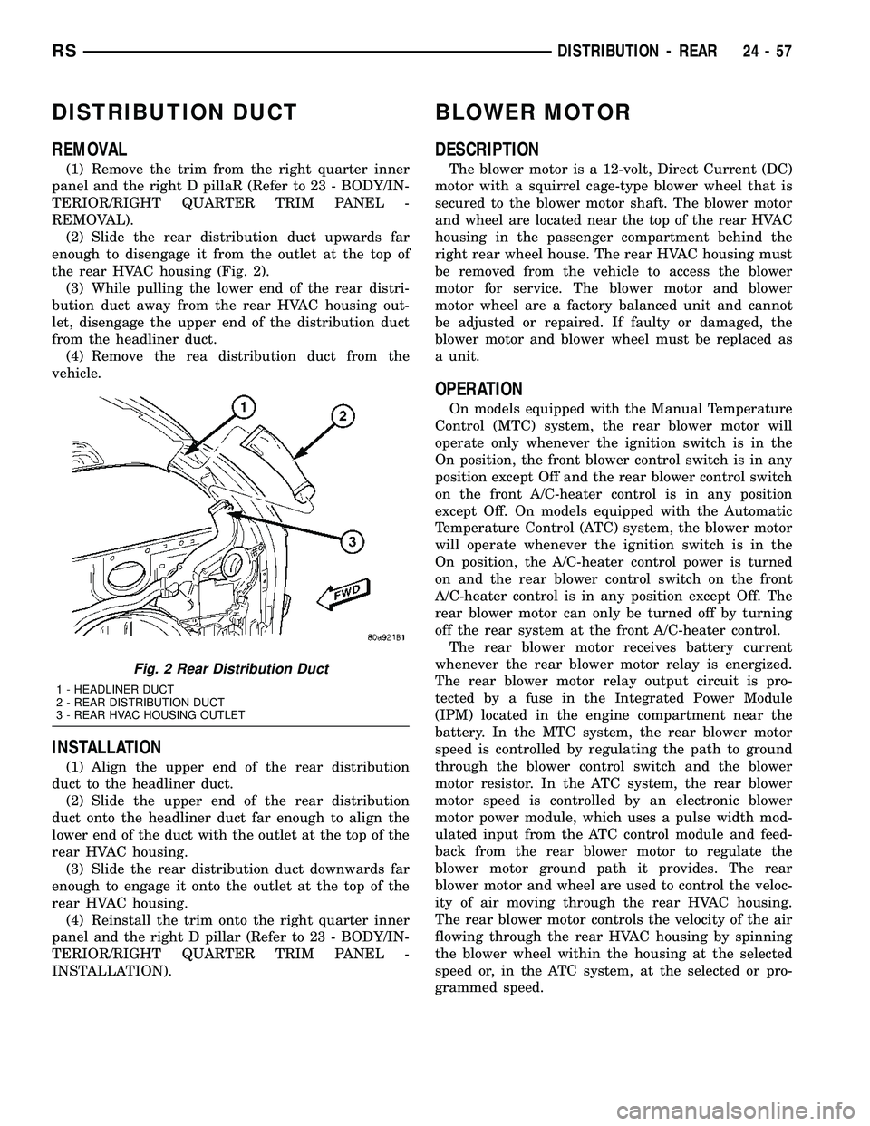
(2) Slide the rear distribution duct upwards far
enough to disengage it from the outlet at the top of
the rear HVAC housing (Fig. 2).
(3) While pulling the lower end of the rear distri-
bution duct away from the rear HVAC housing out-
let, disengage the upper end of the distribution duct
from the headliner duct.
(4) Remove the rea distribution duct from the
vehicle.
INSTALLATION
(1) Align the upper end of the rear distribution
duct to the headliner duct.
(2) Slide the upper end of the rear distribution
duct onto the headliner duct far enough to align the
lower end of the duct with the outlet at the top of the
rear HVAC housing.
(3) Slide the rear distribution duct downwards far
enough to engage it onto the outlet at the top of the
rear HVAC housing.
(4) Reinstall the trim onto the right quarter inner
panel and the right D pillar (Refer to 23 - BODY/IN-
TERIOR/RIGHT QUARTER TRIM PANEL -
INSTALLATION).
BLOWER MOTOR
DESCRIPTION
The blower motor is a 12-volt, Direct Current (DC)
motor with a squirrel cage-type blower wheel that is
secured to the blower motor shaft. The blower motor
and wheel are located near the top of the rear HVAC
housing in the passenger compartment behind the
right rear wheel house. The rear HVAC housing must
be removed from the vehicle to access the blower
motor for service. The blower motor and blower
motor wheel are a factory balanced unit and cannot
be adjusted or repaired. If faulty or damaged, the
blower motor and blower wheel must be replaced as
a unit.
OPERATION
On models equipped with the Manual Temperature
Control (MTC) system, the rear blower motor will
operate only whenever the ignition switch is in the
On position, the front blower control switch is in any
position except Off and the rear blower control switch
on the front A/C-heater control is in any position
except Off. On models equipped with the Automatic
Temperature Control (ATC) system, the blower motor
will operate whenever the ignition switch is in the
On position, the A/C-heater control power is turned
on and the rear blower control switch on the front
A/C-heater control is in any position except Off. The
rear blower motor can only be turned off by turning
off the rear system at the front A/C-heater control.
The rear blower motor receives battery current
whenever the rear blower motor relay is energized.
The rear blower motor relay output circuit is pro-
tected by a fuse in the Integrated Power Module
(IPM) located in the engine compartment near the
battery. In the MTC system, the rear blower motor
speed is controlled by regulating the path to ground
through the blower control switch and the blower
motor resistor. In the ATC system, the rear blower
motor speed is controlled by an electronic blower
motor power module, which uses a pulse width mod-
ulated input from the ATC control module and feed-
back from the rear blower motor to regulate the
blower motor ground path it provides. The rear
blower motor and wheel are used to control the veloc-
ity of air moving through the rear HVAC housing.
The rear blower motor controls the velocity of the air
flowing through the rear HVAC housing by spinning
the blower wheel within the housing at the selected
speed or, in the ATC system, at the selected or pro-
grammed speed.
Fig. 2 Rear Distribution Duct
1 - HEADLINER DUCT
2 - REAR DISTRIBUTION DUCT
3 - REAR HVAC HOUSING OUTLET
RSDISTRIBUTION - REAR24-57
Page 2209 of 2339
DIAGNOSIS AND TESTING
REAR BLOWER MOTOR
BLOWER MOTOR INOPERATIVE
For circuit descriptions and diagrams, refer to the
appropriate wiring information. The wiring informa-
tion includes wiring, diagrams, proper wire and con-
nector repair procedures, further details on wire
harness routing and retention, as well as pin-out and
location views for the various wire harness connec-
tors, splices and grounds.
BLOWER MOTOR ELECTRICAL DIAGNOSIS
(1) Check the fuse (Fuse 12 - 25 ampere) in the
Integrated Power Module (IPM). If OK, go to Step 2.
If not OK, repair the shorted circuit or component as
required and replace the faulty fuse.
(2) Turn the ignition switch to the On position. Be
certain that the rear A/C-heater control power is
turned on. Check for battery voltage at the fuse
(Fuse 12 - 25 ampere) in the IPM. If OK, go to Step
3. If not OK, check the rear blower motor relay.
(3) Turn the ignition switch to the Off position.
Disconnect and isolate the battery negative cable.
Disconnect the rear HVAC wire harness connector
from the rear blower motor resistor block (Manual
Temperature Control) or the rear blower motor power
module (Automatic Temperature Control). Reconnect
the battery negative cable. Turn the ignition switch
to the On position. Be certain that the rear A/C-
heater control power is turned on. Check for battery
voltage at the fused rear blower motor relay output
circuit cavity of the rear HVAC wire harness connec-
tor for the rear blower motor resistor block (MTC) or
the rear blower motor power module (ATC). If OK, go
to Step 4. If not OK, repair the open fused front
blower motor relay output circuit to the IPM as
required.
(4) Turn the ignition switch to the Off position.
Disconnect and isolate the battery negative cable.Disconnect the rear blower motor pigtail wire connec-
tor from the rear HVAC wire harness (MTC) or the
rear blower power module (ATC). Use jumper wires
to connect a battery and ground feeds to the blower
motor pigtail wire connector. The rear blower motor
should operate. If OK with MTC, proceed to diagno-
sis of the rear blower motor resistor block (Refer to
24 - HEATING & AIR CONDITIONING/CONTROLS
- REAR/BLOWER MOTOR RESISTOR - DIAGNOSIS
AND TESTING). If OK with ATC, use a DRBIII scan
tool to diagnose the rear blower motor power module.
Refer to the appropriate diagnostic information. If
not OK with MTC or ATC, replace the faulty rear
blower motor.
BLOWER MOTOR NOISE OR VIBRATION
Refer to the Blower Motor Noise/Vibration Diagno-
sis chart for basic checks of the blower motor when a
vibration or noise is present (Fig. 3).
REMOVAL
WARNING: REFER TO THE APPLICABLE WARN-
INGS AND CAUTIONS FOR THIS SYSTEM BEFORE
PERFORMING THE FOLLOWING OPERATION (Refer
to 24 - HEATING & AIR CONDITIONING/PLUMBING -
WARNING) and (Refer to 24 - HEATING & AIR CON-
DITIONING/PLUMBING - CAUTION).
(1) Remove the rear HVAC housing from the vehi-
cle (Refer to 24 - HEATING & AIR CONDITIONING/
DISTRIBUTION/HVAC HOUSING - REMOVAL).
(2) Disconnect the rear blower motor pigtail wire
connector.
NOTE: With the Manual Temperature Control sys-
tem, the blower motor pigtail wire is connected to a
take out and connector of the rear HVAC wire har-
ness. With the Automatic Temperature Control sys-
tem , the blower pigtail wire is connected to a
receptacle on the blower motor power module.
24 - 58 DISTRIBUTION - REARRS
BLOWER MOTOR (Continued)
Page 2211 of 2339

(3) Remove the three screws that secure the rear
blower motor to the outboard side of the rear HVAC
housing (Fig. 4).
(4) Remove the rear blower motor from the rear
HVAC housing.
INSTALLATION
(1) Position the rear blower motor into the rear
HVAC housing.
(2) Install the three screws that secure the blower
motor to the rear HVAC housing. Tighten the screws
to 2 N´m (17 in. lbs.).
(3) Reconnect the rear blower motor pigtail wire
connector.
NOTE: With the Manual Temperature Control system
, the blower pigtail wire is connected to a take out
and connector of the rear HVAC wire harness. With
the Automatic Temperature Control system, the
blower pigtail wire is connected to a receptacle on
the blower motor power module.(4) Install the rear HVAC housing (Refer to 24 -
HEATING & AIR CONDITIONING/DISTRIBUTION/
HVAC HOUSING - INSTALLATION).
HVAC HOUSING
REMOVAL
WARNING: REFER TO THE APPLICABLE WARN-
INGS AND CAUTIONS FOR THIS SYSTEM BEFORE
PERFORMING THE FOLLOWING OPERATION (Refer
to 24 - HEATING & AIR CONDITIONING/PLUMBING -
FRONT - WARNING - A/C PLUMBING) and (Refer to
24 - HEATING & AIR CONDITIONING/PLUMBING -
FRONT - CAUTION - A/C PLUMBING).
(1) Recover the refrigerant from the refrigerant
system (Refer to 24 - HEATING & AIR CONDITION-
ING/PLUMBING - FRONT/REFRIGERANT - STAN-
DARD PROCEDURE - REFRIGERANT
RECOVERY).
(2) Drain the engine cooling system (Refer to 7 -
COOLING - STANDARD PROCEDURE - COOLING
SYSTEM DRAIN).
(3) Disconnect and isolate the negative battery
cable.
(4) Raise and support the vehicle.
(5) Remove the nut that secures the underbody
refrigerant line sealing plate to the rear evaporator
extension line tapping plate that extends through the
rear floor panel behind the right rear wheel housing
(Fig. 5) and (Fig. 6).
(6) Disconnect the underbody refrigerant lines
from the rear evaporator extension line tapping plate
and remove and discard the O-ring seals.
(7) Install plugs in, or tape over the opened under-
body refrigerant line fittings and the evaporator
extension line sealing plate ports.
(8) Remove the nuts from the mounting studs that
secure the rear HVAC housing to the rear floor panel
behind the right rear wheel housing (Fig. 7).
(9) Lower the vehicle.
(10) Remove the right quarter trim panel and
right D-pillar trim panel from the quarter inner
panel (Refer to 23 - BODY/INTERIOR/QUARTER
TRIM PANEL - REMOVAL).
(11) Remove the rear distribution duct from the
rear HVAC housing and the rear roof duct (Refer to
24 - HEATING & AIR CONDITIONING/DISTRIBU-
TION/AIR OUTLETS - REMOVAL).
(12) Disconnect the body wire harness connector
for the rear HVAC housing from the rear HVAC wire
harness connector located near the expansion valve
at the back of the housing.
Fig. 4 Rear Blower Motor
1 - REAR HVAC HOUSING
2 - REAR BLOWER MOTOR
3 - SCREW (3)
4 - BLOWER MOTOR PIGTAIL WIRE
24 - 60 DISTRIBUTION - REARRS
BLOWER MOTOR (Continued)
Page 2218 of 2339
DIAGNOSIS AND TESTING
REFRIGERANT SYSTEM LEAKS
WARNING: R-134a SERVICE EQUIPMENT OR VEHI-
CLE A/C SYSTEM SHOULD NOT BE PRESSURE
TESTED OR LEAK TESTED WITH COMPRESSED
AIR. MIXTURE OF AIR and R-134a CAN BE COMBUS-
TIBLE AT ELEVATED PRESSURES. THESE MIX-
TURES ARE POTENTIALLY DANGEROUS AND MAY
RESULT IN FIRE OR EXPLOSION CAUSING INJURY
OR PROPERTY DAMAGE.
AVOID BREATHING A/C REFRIGERANT AND LUBRI-
CANT VAPOR OR MIST. EXPOSURE MAY IRRITATE
EYES, NOSE AND THROAT. USE ONLY APPROVED
SERVICE EQUIPMENT MEETING SAE REQUIRE-
MENTS TO DISCHARGE R-134a SYSTEM. IF ACCI-
DENTAL SYSTEM DISCHARGE OCCURS, VENTILATE
WORK AREA BEFORE RESUMING SERVICE.
If the A/C system is not cooling properly, determine
if the refrigerant system is fully charged with R-134a
(Refer to 24 - HEATING & AIR CONDITIONING/
PLUMBING - FRONT/REFRIGERANT - DIAGNO-
SIS AND TESTING - REFRIGERANT SYSTEM
CHARGE LEVEL). If while performing this test A/C
liquid line pressure is less than 345 kPa (50 psi) pro-
ceed to System Empty procedure. If liquid line pres-
sure is greater than 345 kPa (50 psi) proceed to
System Low procedure. If the refrigerant system is
empty or low in refrigerant charge, a leak at any line
fitting or component seal is likely. A review of the fit-
tings, lines and components for oily residue is an
indication of the leak location.
To detect a leak in the refrigerant system, perform
one of the following procedures as indicated by the
results of the refrigerant system charge level test.
SYSTEM EMPTY
(1) Evacuate the refrigerant system to the lowest
degree of vacuum possible (approx. 28 in Hg.) (Refer
to 24 - HEATING & AIR CONDITIONING/PLUMB-
ING - FRONT/REFRIGERANT - STANDARD PRO-
CEDURE - REFRIGERANT SYSTEM EVACUATE).
Determine if the system holds a vacuum for 15 min-
utes. If vacuum is held, a leak is probably not
present. If system will not maintain vacuum level,
proceed with this procedure.
(2) Prepare a 0.284 Kg. (10 oz.) refrigerant charge
to be injected into the system.
(3) Connect and dispense 0.284 Kg. (10 oz.) of
refrigerant into the evacuated refrigerant system
(Refer to 24 - HEATING & AIR CONDITIONING/
PLUMBING - FRONT/REFRIGERANT - STANDARD
PROCEDURE - REFRIGERANT SYSTEM CHARGE).
(4) Proceed to the SYSTEM LOW procedures.SYSTEM LOW
(1) Position the vehicle in a wind-free work area.
This will aid in detecting small leaks.
(2) Bring the refrigerant system up to operating
temperature and pressure. This is done by allowing
the engine to run for five minutes with the system
set to the following:
²Transaxle in Park
²Engine idling
²Rear A/C Off (if equipped)
²A/C controls set to 100 percent outside air
²Blower switch in the highest speed position
²A/C in the ON position
²Front windows open
CAUTION: A leak detector designed for R-12 refrig-
erant (only) will not detect leaks in a R-134a refrig-
erant system.
(3) Shut off the vehicle and wait 2 to 7 minutes.
Then use an Electronic Leak Detector that is
designed to detect R-134a type refrigerant and search
for leaks. Fittings, lines, or components that appear
to be oily usually indicates a refrigerant leak. To
inspect the evaporator core for leaks, insert the leak
detector probe into the drain tube opening or a heat
duct. A R-134a dye is available to aid in leak detec-
tion, use only DaimlerChrysler approved refrigerant
dye.
SYSTEM CHARGE LEVEL TEST
WARNING: REFER TO THE APPLICABLE WARN-
INGS AND CAUTIONS FOR THIS SYSTEM BEFORE
PERFORMING THE FOLLOWING OPERATION (Refer
to 24 - HEATING & AIR CONDITIONING/PLUMBING -
FRONT - WARNING - A/C PLUMBING) and (Refer to
24 - HEATING & AIR CONDITIONING/PLUMBING -
FRONT - CAUTION - A/C PLUMBING).
NOTE: Always refer to the underhood HVAC Speci-
fication Label for the refrigerant fill specification of
the vehicle being serviced.
The procedure that follows should be used to deter-
mine whether the refrigerant system contains the
proper refrigerant charge. Symptoms of an improper
refrigerant charge (low) include: poor air conditioner
performance, fog emitted from the air conditioner
outlets, a hissing sound from the expansion valve/
evaporator area. There are two different methods
with which the refrigerant charge level may be
tested:
1. Using a DRBIIItscan tool, a thermocouple and
the Charge Determination Chart (Fig. 1). Refer to
the appropriate diagnostic information.
RSPLUMBING - FRONT24-67
PLUMBING - FRONT (Continued)
Page 2219 of 2339
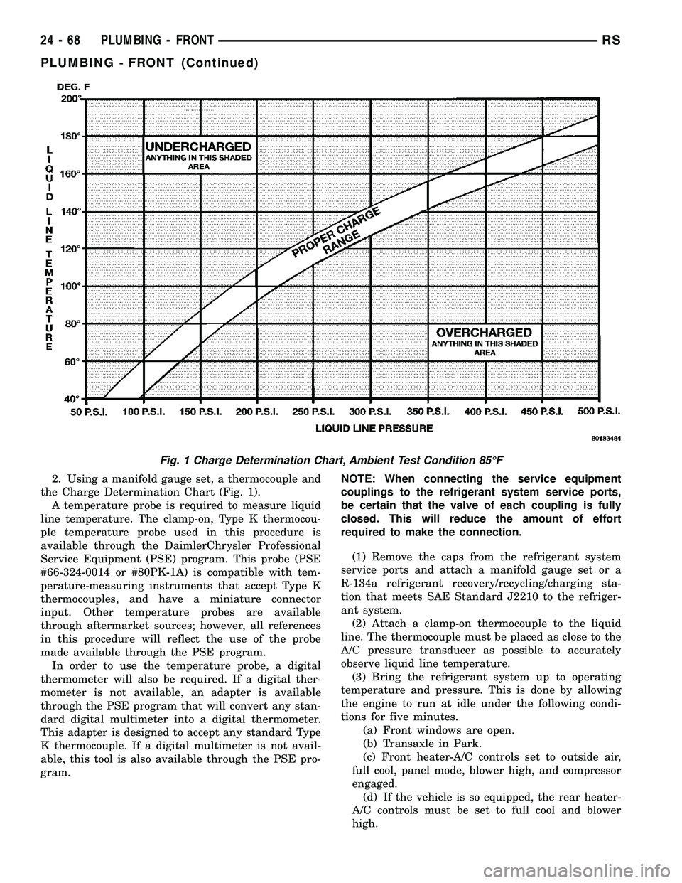
2. Using a manifold gauge set, a thermocouple and
the Charge Determination Chart (Fig. 1).
A temperature probe is required to measure liquid
line temperature. The clamp-on, Type K thermocou-
ple temperature probe used in this procedure is
available through the DaimlerChrysler Professional
Service Equipment (PSE) program. This probe (PSE
#66-324-0014 or #80PK-1A) is compatible with tem-
perature-measuring instruments that accept Type K
thermocouples, and have a miniature connector
input. Other temperature probes are available
through aftermarket sources; however, all references
in this procedure will reflect the use of the probe
made available through the PSE program.
In order to use the temperature probe, a digital
thermometer will also be required. If a digital ther-
mometer is not available, an adapter is available
through the PSE program that will convert any stan-
dard digital multimeter into a digital thermometer.
This adapter is designed to accept any standard Type
K thermocouple. If a digital multimeter is not avail-
able, this tool is also available through the PSE pro-
gram.NOTE: When connecting the service equipment
couplings to the refrigerant system service ports,
be certain that the valve of each coupling is fully
closed. This will reduce the amount of effort
required to make the connection.
(1) Remove the caps from the refrigerant system
service ports and attach a manifold gauge set or a
R-134a refrigerant recovery/recycling/charging sta-
tion that meets SAE Standard J2210 to the refriger-
ant system.
(2) Attach a clamp-on thermocouple to the liquid
line. The thermocouple must be placed as close to the
A/C pressure transducer as possible to accurately
observe liquid line temperature.
(3) Bring the refrigerant system up to operating
temperature and pressure. This is done by allowing
the engine to run at idle under the following condi-
tions for five minutes.
(a) Front windows are open.
(b) Transaxle in Park.
(c) Front heater-A/C controls set to outside air,
full cool, panel mode, blower high, and compressor
engaged.
(d) If the vehicle is so equipped, the rear heater-
A/C controls must be set to full cool and blower
high.
Fig. 1 Charge Determination Chart, Ambient Test Condition 85ÉF
24 - 68 PLUMBING - FRONTRS
PLUMBING - FRONT (Continued)
Page 2223 of 2339

(4) Open both the suction and discharge valves,
then open the charge valve to allow the heated
refrigerant to flow into the system.
(5) When the transfer of refrigerant has stopped,
close both the suction and discharge valves.
(6) If all of the refrigerant charge did not transfer
from the dispensing device, open all of the windows
in the vehicle and set the heater-air conditioner con-
trols so that the compressor is engaged and the
blower motor is operating at its lowest speed setting.
Run the engine at a steady high idle (about 1400
rpm). If the compressor will not engage, test the com-
pressor clutch control circuit and repair as required.
(7) Open the suction valve to allow the remaining
refrigerant to transfer to the refrigerant system.
WARNING: TAKE CARE NOT TO OPEN THE DIS-
CHARGE (HIGH PRESSURE) VALVE AT THIS TIME.
(8) Close the suction valve and test the system
performance. (Refer to 24 - HEATING & AIR CON-
DITIONING - STANDARD PROCEDURE - A/C PER-
FORMANCE TEST).
(9) Disconnect the charging station and manifold
gauge set from the refrigerant system service ports.
(10) Reinstall the caps onto the refrigerant system
service ports.
(11) Run the HVAC Control Cooldown test to ver-
ify proper operation(Refer to 24 - HEATING & AIR
CONDITIONING - DIAGNOSIS AND TESTING).
A/C COMPRESSOR
DESCRIPTION
A/C COMPRESSOR
Vehicles equipped with the 2.4L gasoline, 2.5L die-
sel, 2.8L diesel and 3.3L gasoline engines with the
front heating-A/C system only, use the Denso 10S17
A/C compressor. Vehicles equipped with the 3.3L and
the 3.8L gasoline engines with the optional rear heat-
ing-A/C system use the Denso 10S20 A/C compressor.
Both A/C compressors include an integral high pres-
sure relief valve. The A/C compressor is secured to a
mounting bracket on the 2.4L gasoline engine and
directly to the cylinder block on the 2.5L diesel, 2.8L
diesel, 3.3L gasoline and 3.8L gasoline engines.
HIGH PRESSURE RELIEF VALVE
A high pressure relief valve is located on the rear
of the A/C compressor. This mechanical valve is
designed to vent refrigerant from the A/C system to
protect against damage to the compressor and other
system components, caused by condenser air flow
restriction or an overcharge of refrigerant.
OPERATION
A/C COMPRESSOR
The A/C compressor is driven by the engine
through an electric clutch, drive pulley and belt
arrangement. The compressor is lubricated by refrig-
erant oil that is circulated throughout the refrigerant
system with the refrigerant.
The compressor draws in low-pressure refrigerant
vapor from the evaporator through its suction port. It
then compresses the refrigerant into a high-pressure,
high-temperature refrigerant vapor. The compressor
pumps the high-pressure refrigerant vapor to the
condenser through the compressor discharge port.
The compressor cannot be repaired. If faulty or
damaged, the entire compressor assembly must be
replaced. The compressor clutch, pulley and clutch
coil are available for service.
HIGH PRESSURE RELIEF VALVE
The high pressure relief valve vents the system
when a discharge pressure of 3445 to 4135 kPa (500
to 600 psi) or above is reached. The valve closes
when a minimum discharge pressure of 2756 kPa
(400 psi) is reached.
The high pressure relief valve vents only enough
refrigerant to reduce the system pressure, and then
re-seats itself. The majority of the refrigerant is con-
served in the system. If the valve vents refrigerant, it
does not mean that the valve is faulty.
The high pressure relief valve is a factory-cali-
brated unit. The valve cannot be adjusted or
repaired, and must not be removed or otherwise dis-
turbed. The valve is only serviced as a part of the
compressor assembly.
DIAGNOSIS AND TESTING
A/C COMPRESSOR NOISE DIAGNOSIS
Excessive noise while the air conditioning compres-
sor is operating can be caused by loose compressor
mounts, a loose compressor clutch, or high operating
pressures in the refrigerant system. Verify compres-
sor drive belt condition, proper compressor mounting,
correct refrigerant charge level, and compressor head
pressure before compressor repair is performed.
With the close tolerances within the compressor, it
is possible to experience a temporary lockup. The
longer the compressor is inactive, the more likely the
condition is to occur. This condition is the result of
normal refrigerant migration within the refrigerant
system caused by ambient temperature changes. The
refrigerant migration may wash the refrigerant oil
out of the compressor.
24 - 72 PLUMBING - FRONTRS
PLUMBING - FRONT (Continued)
Page 2233 of 2339
DIAGNOSIS AND TESTING
FRONT A/C EXPANSION VALVE
WARNING: REFER TO THE APPLICABLE WARN-
INGS AND CAUTIONS FOR THIS SYSTEM BEFORE
PERFORMING THE FOLLOWING OPERATION (Refer
to 24 - HEATING & AIR CONDITIONING/PLUMBING -
FRONT - WARNING - A/C PLUMBING) and (Refer to
24 - HEATING & AIR CONDITIONING/PLUMBING -
FRONT - CAUTION - A/C PLUMBING).
NOTE: The A/C expansion valve should only be
tested following testing of the A/C compressor.
NOTE: Liquid CO
2is required to test the A/C expan-
sion valve. This material is available from most
welding supply facilities. Liquid CO
2is also avail-
able from companies which service and sell fire
extinguishers.
When testing the A/C expansion valve, the work
area and the vehicle temperature must be 21É to 27É
C (70É to 85É F). To test the expansion valve:
(1) Connect a charging station or manifold gauge
set to the refrigerant system service ports. Verify the
refrigerant charge level.
(2) Close all doors, windows and vents to the pas-
senger compartment.
(3) Set the A/C-heater controls so that the A/C
compressor is operating, the temperature control is
in the highest temperature position, the mode door is
directing the output to the floor outlets, and the
blower motor is operating at the highest speed set-
ting.
(4) Start the engine and allow it to idle. After the
engine has reached normal operating temperature,
allow the passenger compartment to heat up. This
will create the need for maximum refrigerant flow
into the A/C evaporator.
(5) If the refrigerant charge is sufficient, the dis-
charge (high pressure) gauge should read 965 kPa to
1655 kPa (140 psi to 240 psi). The suction (low pres-
sure) gauge should read 138 kPa to 207 kPa (20 psi
to 30 psi). If OK, go to Step 6. If not OK, replace the
faulty A/C expansion valve.
WARNING:
PROTECT THE SKIN AND EYES FROM EXPOSURE
TO LIQUID CO
2OR PERSONAL INJURY CAN
RESULT.
(6) If the suction (low pressure) gauge reads
within the specified range, freeze the A/C expansion
valve for 30 seconds using liquid CO
2or another suit-able super-cold material.Do not spray R-134a or
R-12 refrigerant on the A/C expansion valve for
this test.The suction (low pressure) gauge reading
should drop by 69 kPa (10 psi). If OK, go to Step 7 If
not OK, replace the faulty A/C expansion valve.
(7) Allow the expansion valve control head to thaw.
The suction (low pressure) gauge reading should sta-
bilize at 138 kPa to 207 kPa (20 psi to 30 psi). If not
OK, replace the faulty A/C expansion valve.
(8) When expansion valve testing is complete, test
the overall A/C system performance (Refer to 24 -
HEATING & AIR CONDITIONING - DIAGNOSIS
AND TESTING - A/C PERFORMANCE TEST).
REMOVAL
WARNING: REFER TO THE APPLICABLE WARN-
INGS AND CAUTIONS FOR THIS SYSTEM BEFORE
PERFORMING THE FOLLOWING OPERATION (Refer
to 24 - HEATING & AIR CONDITIONING/PLUMBING -
FRONT - WARNING - A/C PLUMBING) and (Refer to
24 - HEATING & AIR CONDITIONING/PLUMBING -
FRONT - CAUTION - A/C PLUMBING).
(1) Recover the refrigerant from the refrigerant
system (Refer to 24 - HEATING & AIR CONDITION-
ING/PLUMBING - FRONT/REFRIGERANT - STAN-
DARD PROCEDURE - REFRIGERANT
RECOVERY).
(2) Disconnect and isolate the battery negative
cable.
(3) Remove the air cleaner housing from the right
side of the engine compartment.
(4) Disconnect the drain tube from the wiper mod-
ule drain on the right side of the engine compart-
ment.
(5) Disconnect the wire harness connector from the
A/C pressure transducer (Fig. 16).
(6) Remove the screw that secures the front liquid
line rear section fitting to the top of the receiver/
drier.
(7) Disconnect the liquid line fitting from the
receiver/drier outlet port.
(8) Remove the seal from the liquid line fitting and
discard.
(9) Install plugs in, or tape over the opened liquid
line fitting and the receiver/drier outlet port.
(10) Remove the nut that secures the suction line
and liquid line fittings to the stud on the A/C expan-
sion valve.
(11) Disconnect the suction line and liquid line fit-
tings from the A/C expansion valve and move the
lines out of the way.
(12) Remove the seals from the suction line and
liquid line fittings and discard.
24 - 82 PLUMBING - FRONTRS
EXPANSION VALVE (Continued)