service CHRYSLER VOYAGER 2005 Service Manual
[x] Cancel search | Manufacturer: CHRYSLER, Model Year: 2005, Model line: VOYAGER, Model: CHRYSLER VOYAGER 2005Pages: 2339, PDF Size: 59.69 MB
Page 1417 of 2339
COLUMN
TABLE OF CONTENTS
page page
COLUMN
DESCRIPTION - STEERING COLUMN.......10
WARNING
WARNINGS AND CAUTIONS.............10
DIAGNOSIS AND TESTING - STEERING
COLUMN............................11
REMOVAL.............................11
INSTALLATION.........................16
SPECIFICATIONS
COLUMN FASTENER TORQUE...........17
IGNITION SWITCH
REMOVAL.............................17
INSTALLATION.........................19
KEY/LOCK CYLINDER
DESCRIPTION.........................20OPERATION...........................20
REMOVAL.............................20
INSTALLATION.........................20
SHROUD - LOWER
REMOVAL.............................21
INSTALLATION.........................21
SHROUD - UPPER
REMOVAL.............................22
INSTALLATION.........................22
STEERING WHEEL
REMOVAL.............................23
INSTALLATION.........................24
COLUMN
DESCRIPTION - STEERING COLUMN
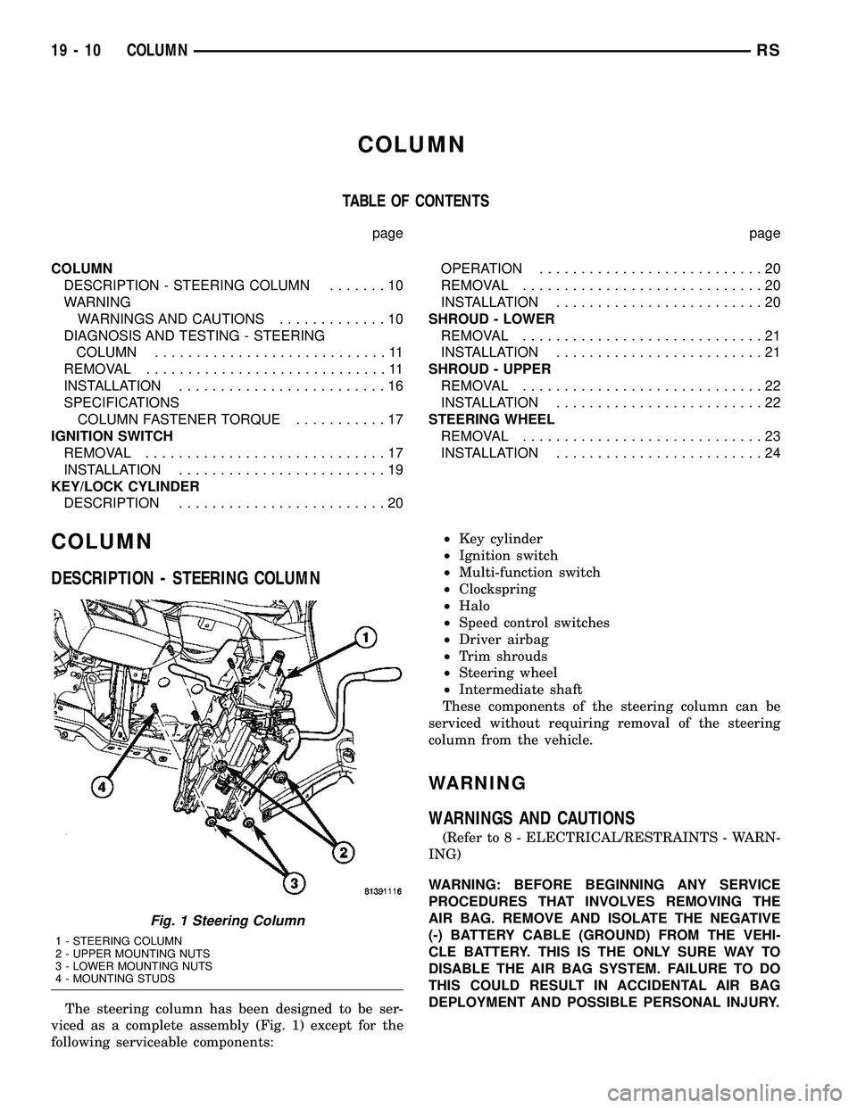
The steering column has been designed to be ser-
viced as a complete assembly (Fig. 1) except for the
following serviceable components:²Key cylinder
²Ignition switch
²Multi-function switch
²Clockspring
²Halo
²Speed control switches
²Driver airbag
²Trim shrouds
²Steering wheel
²Intermediate shaft
These components of the steering column can be
serviced without requiring removal of the steering
column from the vehicle.
WARNING
WARNINGS AND CAUTIONS
(Refer to 8 - ELECTRICAL/RESTRAINTS - WARN-
ING)
WARNING: BEFORE BEGINNING ANY SERVICE
PROCEDURES THAT INVOLVES REMOVING THE
AIR BAG. REMOVE AND ISOLATE THE NEGATIVE
(-) BATTERY CABLE (GROUND) FROM THE VEHI-
CLE BATTERY. THIS IS THE ONLY SURE WAY TO
DISABLE THE AIR BAG SYSTEM. FAILURE TO DO
THIS COULD RESULT IN ACCIDENTAL AIR BAG
DEPLOYMENT AND POSSIBLE PERSONAL INJURY.
Fig. 1 Steering Column
1 - STEERING COLUMN
2 - UPPER MOUNTING NUTS
3 - LOWER MOUNTING NUTS
4 - MOUNTING STUDS
19 - 10 COLUMNRS
Page 1418 of 2339
WARNING: THE AIR BAG SYSTEM IS A SENSITIVE,
COMPLEX ELECTRO-MECHANICAL UNIT. BEFORE
ATTEMPTING TO DIAGNOSE, REMOVE OR INSTALL
THE AIR BAG SYSTEM COMPONENTS YOU MUST
FIRST DISCONNECT AND ISOLATE THE BATTERY
NEGATIVE (GROUND) CABLE. THEN WAIT TWO
MINUTES FOR THE SYSTEM CAPACITOR TO DIS-
CHARGE. FAILURE TO DO SO COULD RESULT IN
ACCIDENTAL DEPLOYMENT OF THE AIR BAG AND
POSSIBLE PERSONAL INJURY. THE FASTENERS,
SCREWS, AND BOLTS, ORIGINALLY USED FOR
THE AIR BAG COMPONENTS, HAVE SPECIAL
COATINGS AND ARE SPECIFICALLY DESIGNED
FOR THE AIR BAG SYSTEM. THEY MUST NEVER
BE REPLACED WITH ANY SUBSTITUTES. ANYTIME
A NEW FASTENER IS NEEDED, REPLACE WITH
THE CORRECT FASTENERS PROVIDED IN THE
SERVICE PACKAGE OR FASTENERS LISTED IN
THE PARTS BOOKS.
WARNING: SAFETY GOGGLES SHOULD BE WORN
AT ALL TIMES WHEN WORKING ON STEERING
COLUMNS.
CAUTION: Disconnect negative (ground) cable from
the battery before servicing any column compo-
nent.
CAUTION: Do not attempt to remove the pivot pins
to disassemble the tilting mechanism. Damage will
occur.
DIAGNOSIS AND TESTING - STEERING
COLUMN
For diagnosis of conditions relating to the steering
column, (Refer to 19 - STEERING - DIAGNOSIS
AND TESTING).
REMOVAL
NOTE: Before proceeding, (Refer to 19 - STEERING/
COLUMN - WARNING)(Refer to 8 - ELECTRICAL/RE-
STRAINTS/DRIVER AIRBAG - REMOVAL).
(1) Make sure the front wheels of the vehicle are
in the STRAIGHT AHEAD position before beginning
the column removal procedure.
(2) Disconnect and isolate the negative (ground)
cable from the battery. Wait at least two minutes for
the airbag system reserve capacitor to discharge
before beginning any steering column, instrument
panel, or airbag system/component service.WARNING: WHEN AN UNDEPLOYED AIRBAG IS TO
BE REMOVED FROM THE VEHICLE, FIRST DISCON-
NECT AND ISOLATE THE BATTERY NEGATIVE
(GROUND) CABLE. ALLOW THE AIRBAG SYSTEM
RESERVE CAPACITOR TO DISCHARGE FOR TWO
MINUTES BEFORE BEGINNING ANY AIRBAG SYS-
TEM OR COMPONENT SERVICE. PERSONAL
INJURY MAY RESULT IF THIS PROCEDURE IS NOT
FOLLOWED.
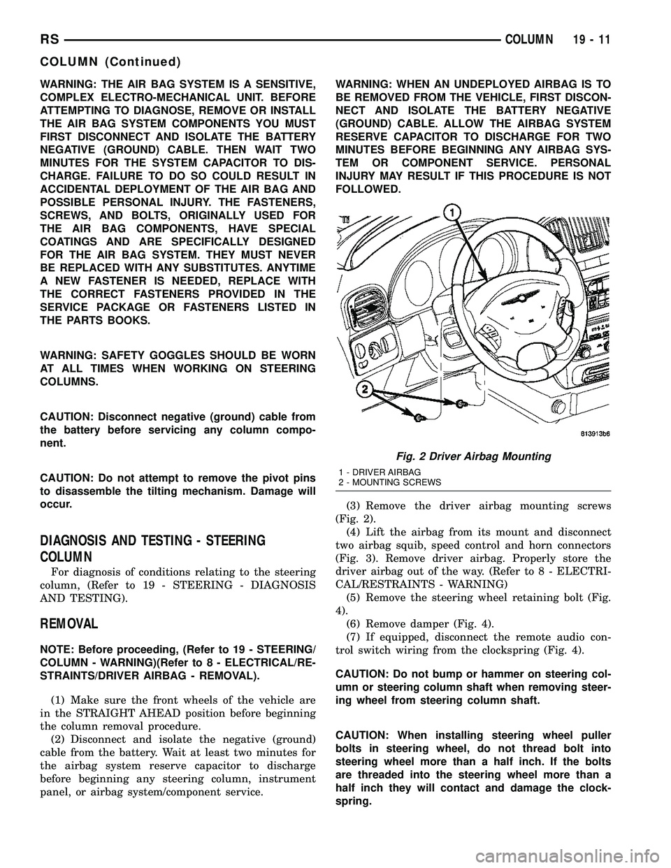
(3) Remove the driver airbag mounting screws
(Fig. 2).
(4) Lift the airbag from its mount and disconnect
two airbag squib, speed control and horn connectors
(Fig. 3). Remove driver airbag. Properly store the
driver airbag out of the way. (Refer to 8 - ELECTRI-
CAL/RESTRAINTS - WARNING)
(5) Remove the steering wheel retaining bolt (Fig.
4).
(6) Remove damper (Fig. 4).
(7) If equipped, disconnect the remote audio con-
trol switch wiring from the clockspring (Fig. 4).
CAUTION: Do not bump or hammer on steering col-
umn or steering column shaft when removing steer-
ing wheel from steering column shaft.
CAUTION: When installing steering wheel puller
bolts in steering wheel, do not thread bolt into
steering wheel more than a half inch. If the bolts
are threaded into the steering wheel more than a
half inch they will contact and damage the clock-
spring.
Fig. 2 Driver Airbag Mounting
1 - DRIVER AIRBAG
2 - MOUNTING SCREWS
RSCOLUMN19-11
COLUMN (Continued)
Page 1430 of 2339
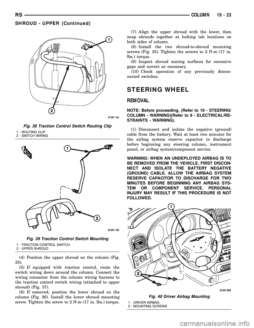
(4) Position the upper shroud on the column (Fig.
35).
(5) If equipped with traction control, route the
switch wiring down around the column. Connect the
wiring connector from the column wiring harness to
the traction control switch wiring (attached to upper
shroud) (Fig. 37).
(6) If removed, position the lower shroud on the
column (Fig. 36). Install the lower shroud mounting
screw. Tighten the screw to 2 N´m (17 in. lbs.) torque.(7) Align the upper shroud with the lower, then
snap shrouds together at locking tab locations on
both sides of column.
(8) Install the two shroud-to-shroud mounting
screws (Fig. 35). Tighten the screws to 2 N´m (17 in.
lbs.) torque.
(9) Inspect shroud mating surfaces for excessive
gaps and correct as necessary.
(10) Check operation of any previously discon-
nected switches.
STEERING WHEEL
REMOVAL
NOTE: Before proceeding, (Refer to 19 - STEERING/
COLUMN - WARNING)(Refer to 8 - ELECTRICAL/RE-
STRAINTS - WARNING).
(1) Disconnect and isolate the negative (ground)
cable from the battery. Wait at least two minutes for
the airbag system reserve capacitor to discharge
before beginning any steering column, instrument
panel, or airbag system/component service.
WARNING: WHEN AN UNDEPLOYED AIRBAG IS TO
BE REMOVED FROM THE VEHICLE, FIRST DISCON-
NECT AND ISOLATE THE BATTERY NEGATIVE
(GROUND) CABLE. ALLOW THE AIRBAG SYSTEM
RESERVE CAPACITOR TO DISCHARGE FOR TWO
MINUTES BEFORE BEGINNING ANY AIRBAG SYS-
TEM OR COMPONENT SERVICE. PERSONAL
INJURY MAY RESULT IF THIS PROCEDURE IS NOT
FOLLOWED.
Fig. 38 Traction Control Switch Routing Clip
1 - ROUTING CLIP
2 - SWITCH WIRING
Fig. 39 Traction Control Switch Mounting
1 - TRACTION CONTROL SWITCH
2 - UPPER SHROUD
Fig. 40 Driver Airbag Mounting
1 - DRIVER AIRBAG
2 - MOUNTING SCREWS
RSCOLUMN19-23
SHROUD - UPPER (Continued)
Page 1448 of 2339

(11) Remove the three front mounting bolts
through the pulley (Fig. 11)
(12) Remove the pump (with pulley) through the
engine compartment rocking it over the aluminum
bracket.
REMOVAL - PUMP (DIESEL)
(1) Remove the negative (-) battery cable from the
battery and isolate cable.
(2) Remove the fill cap from the power steering
fluid reservoir.
(3) Using a siphon pump, remove as much power
steering fluid as possible from the fluid reservoir.
(4) Raise the vehicle. (Refer to LUBRICATION &
MAINTENANCE/HOISTING - STANDARD PROCE-
DURE)
(5) Remove the splash shields from below the
engine compartment.
(6) Remove the accessory drive belt from the power
steering pump pulley. (Refer to 7 - COOLING/AC-
CESSORY DRIVE/DRIVE BELTS - REMOVAL)
(7) Disconnect the fluid supply hose from the
pump (Fig. 12).
(8) Disconnect the pressure hose from the pump
(Fig. 12).
(9) Remove the bolt fastening the stamped bracket
on the rear of the pump to the cast bracket (Fig. 13).
(10) Remove the three front mounting bolts
through the pulley.
(11) Remove the pump from the cast bracket and
vehicle.
DISASSEMBLY - PUMP (PULLEY)
The only serviceable part of the power steering
pump is the pulley. The procedure following is for
removal and installation of the pulley from the pump
once the pump is removed from the vehicle.
Fig. 10 Supply And Pressure Hoses At Pump
1 - PRESSURE HOSE AND FITTING
2 - SUPPLY HOSE AND CLAMP
3 - POWER STEERING PUMP
Fig. 11 Pump Mounting
1 - PUMP REAR MOUNTING BOLT (2001 ONLY)
2 - PUMP FRONT MOUNTING BOLT (3)
3 - TIMING CHAIN COVER AND PUMP BRACKET THRU BOLT
(2001 ONLY)
4 - PUMP BELT PULLEY
5 - POWER STEERING PUMP
6 - BRACKET (2001 ONLY)
Fig. 12 Power Steering Pump - Diesel
1 - PRESSURE HOSE
2 - HOSE CLAMP
3 - SUPPLY HOSE
4 - POWER STEERING PUMP
RSPUMP19-41
PUMP (Continued)
Page 1449 of 2339

(1) Remove the power steering pump from the
vehicle. Refer to Removal And Installation in this
section of the service manual.
(2) Remove the pulley from the shaft of the power
steering pump using Puller C-4333 (Fig. 14).
CAUTION: Do not hammer on power steering pump
pulley. This will damage the pulley and the power
steering pump.
(3) Replace pulley if it is found to be bent, cracked,
or loose.
ASSEMBLY - PUMP (PULLEY)
The only serviceable part of the power steering
pump is the pulley. The procedure following is for
removal and installation of the pulley from the pump
once the pump is removed from the vehicle.
(1) Install the pulley with Installer C-4063 (Fig.
15). Do not use the tool adapters.
(2) Ensure that the tool and the pulley remain
aligned with the pump shaft. Prevent the pulley from
being cocked on the shaft.
(3) Install the pulley until it is flush with the end
of the power steering pump shaft (Fig. 16).
(4) Install the power steering pump on the vehicle.
Fig. 13 Pump And Brackets - Diesel
1 - CAST BRACKET
2 - STAMPED BRACKET
3 - POWER STEERING PUMP
Fig. 14 Pulley Removal
1 - POWER STEERING PUMP DRIVE PULLEY
2 - SPECIAL TOOL C-4333
Fig. 15 Pulley Installation
1 - POWER STEERING PUMP DRIVE PULLEY
2 - SPECIAL TOOL
C-4063±A
Fig. 16 Pulley To Pump Shaft Location
1 - PULLEY
2 - PUMP BODY
3 - PUMP SHAFT
4 - HUB
19 - 42 PUMPRS
PUMP (Continued)
Page 1462 of 2339

TRANSMISSION/TRANSAXLE
TABLE OF CONTENTS
page page
40TE AUTOMATIC TRANSAXLE..............141TE AUTOMATIC TRANSAXLE............146
40TE AUTOMATIC TRANSAXLE
TABLE OF CONTENTS
page page
40TE AUTOMATIC TRANSAXLE
DESCRIPTION..........................2
OPERATION............................4
DIAGNOSIS AND TESTING
DIAGNOSIS AND TESTING - 4XTE
TRANSAXLE GENERAL DIAGNOSIS........5
DIAGNOSIS AND TESTING - ROAD TEST....5
DIAGNOSIS AND TESTING - HYDRAULIC
PRESSURE TESTS.....................6
DIAGNOSIS AND TESTING - CLUTCH AIR
PRESSURE TESTS.....................8
DIAGNOSIS AND TESTING - TORQUE
CONVERTER HOUSING FLUID LEAKAGE....9
REMOVAL.............................9
DISASSEMBLY.........................12
ASSEMBLY............................29
INSTALLATION.........................51
SCHEMATICS AND DIAGRAMS
4XTE TRANSAXLE HYDRAULIC
SCHEMATICS........................54
SPECIFICATIONS - 41TE TRANSAXLE.......66
SPECIAL TOOLS.......................68
ACCUMULATOR
DESCRIPTION.........................73
OPERATION...........................73
DRIVING CLUTCHES
DESCRIPTION.........................74
OPERATION...........................74
FINAL DRIVE
DESCRIPTION.........................74
OPERATION...........................75
DISASSEMBLY.........................75
ASSEMBLY............................78
ADJUSTMENTS
DIFFERENTIAL BEARING PRELOAD
MEASUREMENT AND ADJUSTMENT......79FLUID
STANDARD PROCEDURE
FLUID LEVEL AND CONDITION CHECK....82
STANDARD PROCEDURE - FLUID AND
FILTER SERVICE......................82
GEAR SHIFT CABLE
REMOVAL.............................84
HOLDING CLUTCHES
DESCRIPTION.........................86
OPERATION...........................86
INPUT CLUTCH ASSEMBLY
DISASSEMBLY.........................86
ASSEMBLY............................95
OIL PUMP
DESCRIPTION........................110
OPERATION..........................110
DISASSEMBLY........................110
ASSEMBLY...........................112
PLANETARY GEARTRAIN
DESCRIPTION........................112
OPERATION..........................112
SEAL - OIL PUMP
REMOVAL............................113
INSTALLATION........................113
SHIFT INTERLOCK SOLENOID
DESCRIPTION........................113
OPERATION..........................114
DIAGNOSIS AND TESTING - BRAKE/
TRANSMISSION SHIFT INTERLOCK
SOLENOID..........................115
REMOVAL............................115
INSTALLATION........................116
SOLENOID/PRESSURE SWITCH ASSY
DESCRIPTION........................117
OPERATION..........................118
REMOVAL............................118
INSTALLATION........................119
RSTRANSMISSION/TRANSAXLE21-1
Page 1480 of 2339
NOTE: The 2/4 Clutch Piston has bonded seals
which are not individually serviceable. Seal replace-
ment requires replacement of the piston assembly.
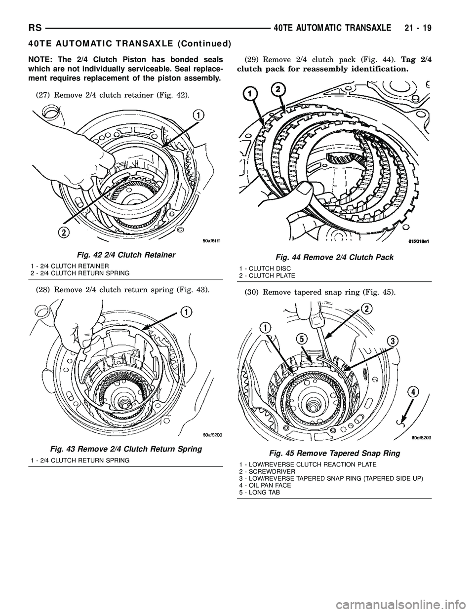
(27) Remove 2/4 clutch retainer (Fig. 42).
(28) Remove 2/4 clutch return spring (Fig. 43).(29) Remove 2/4 clutch pack (Fig. 44).Tag 2/4
clutch pack for reassembly identification.
(30) Remove tapered snap ring (Fig. 45).
Fig. 42 2/4 Clutch Retainer
1 - 2/4 CLUTCH RETAINER
2 - 2/4 CLUTCH RETURN SPRING
Fig. 43 Remove 2/4 Clutch Return Spring
1 - 2/4 CLUTCH RETURN SPRING
Fig. 44 Remove 2/4 Clutch Pack
1 - CLUTCH DISC
2 - CLUTCH PLATE
Fig. 45 Remove Tapered Snap Ring
1 - LOW/REVERSE CLUTCH REACTION PLATE
2 - SCREWDRIVER
3 - LOW/REVERSE TAPERED SNAP RING (TAPERED SIDE UP)
4 - OIL PAN FACE
5 - LONG TAB
RS40TE AUTOMATIC TRANSAXLE21-19
40TE AUTOMATIC TRANSAXLE (Continued)
Page 1489 of 2339
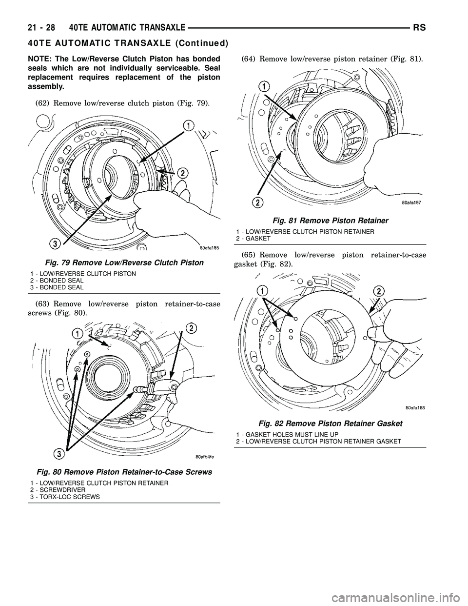
NOTE: The Low/Reverse Clutch Piston has bonded
seals which are not individually serviceable. Seal
replacement requires replacement of the piston
assembly.
(62) Remove low/reverse clutch piston (Fig. 79).
(63) Remove low/reverse piston retainer-to-case
screws (Fig. 80).(64) Remove low/reverse piston retainer (Fig. 81).
(65) Remove low/reverse piston retainer-to-case
gasket (Fig. 82).
Fig. 79 Remove Low/Reverse Clutch Piston
1 - LOW/REVERSE CLUTCH PISTON
2 - BONDED SEAL
3 - BONDED SEAL
Fig. 80 Remove Piston Retainer-to-Case Screws
1 - LOW/REVERSE CLUTCH PISTON RETAINER
2 - SCREWDRIVER
3 - TORX-LOC SCREWS
Fig. 81 Remove Piston Retainer
1 - LOW/REVERSE CLUTCH PISTON RETAINER
2 - GASKET
Fig. 82 Remove Piston Retainer Gasket
1 - GASKET HOLES MUST LINE UP
2 - LOW/REVERSE CLUTCH PISTON RETAINER GASKET
21 - 28 40TE AUTOMATIC TRANSAXLERS
40TE AUTOMATIC TRANSAXLE (Continued)
Page 1491 of 2339
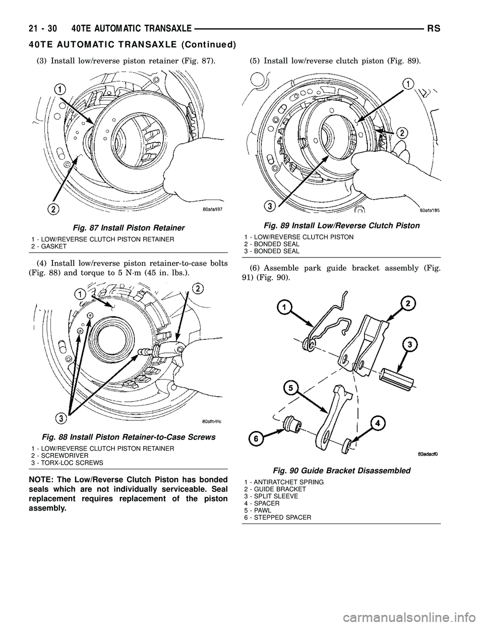
(3) Install low/reverse piston retainer (Fig. 87).
(4) Install low/reverse piston retainer-to-case bolts
(Fig. 88) and torque to 5 N´m (45 in. lbs.).
NOTE: The Low/Reverse Clutch Piston has bonded
seals which are not individually serviceable. Seal
replacement requires replacement of the piston
assembly.(5) Install low/reverse clutch piston (Fig. 89).
(6) Assemble park guide bracket assembly (Fig.
91) (Fig. 90).
Fig. 87 Install Piston Retainer
1 - LOW/REVERSE CLUTCH PISTON RETAINER
2 - GASKET
Fig. 88 Install Piston Retainer-to-Case Screws
1 - LOW/REVERSE CLUTCH PISTON RETAINER
2 - SCREWDRIVER
3 - TORX-LOC SCREWS
Fig. 89 Install Low/Reverse Clutch Piston
1 - LOW/REVERSE CLUTCH PISTON
2 - BONDED SEAL
3 - BONDED SEAL
Fig. 90 Guide Bracket Disassembled
1 - ANTIRATCHET SPRING
2 - GUIDE BRACKET
3 - SPLIT SLEEVE
4 - SPACER
5-PAWL
6 - STEPPED SPACER
21 - 30 40TE AUTOMATIC TRANSAXLERS
40TE AUTOMATIC TRANSAXLE (Continued)
Page 1505 of 2339
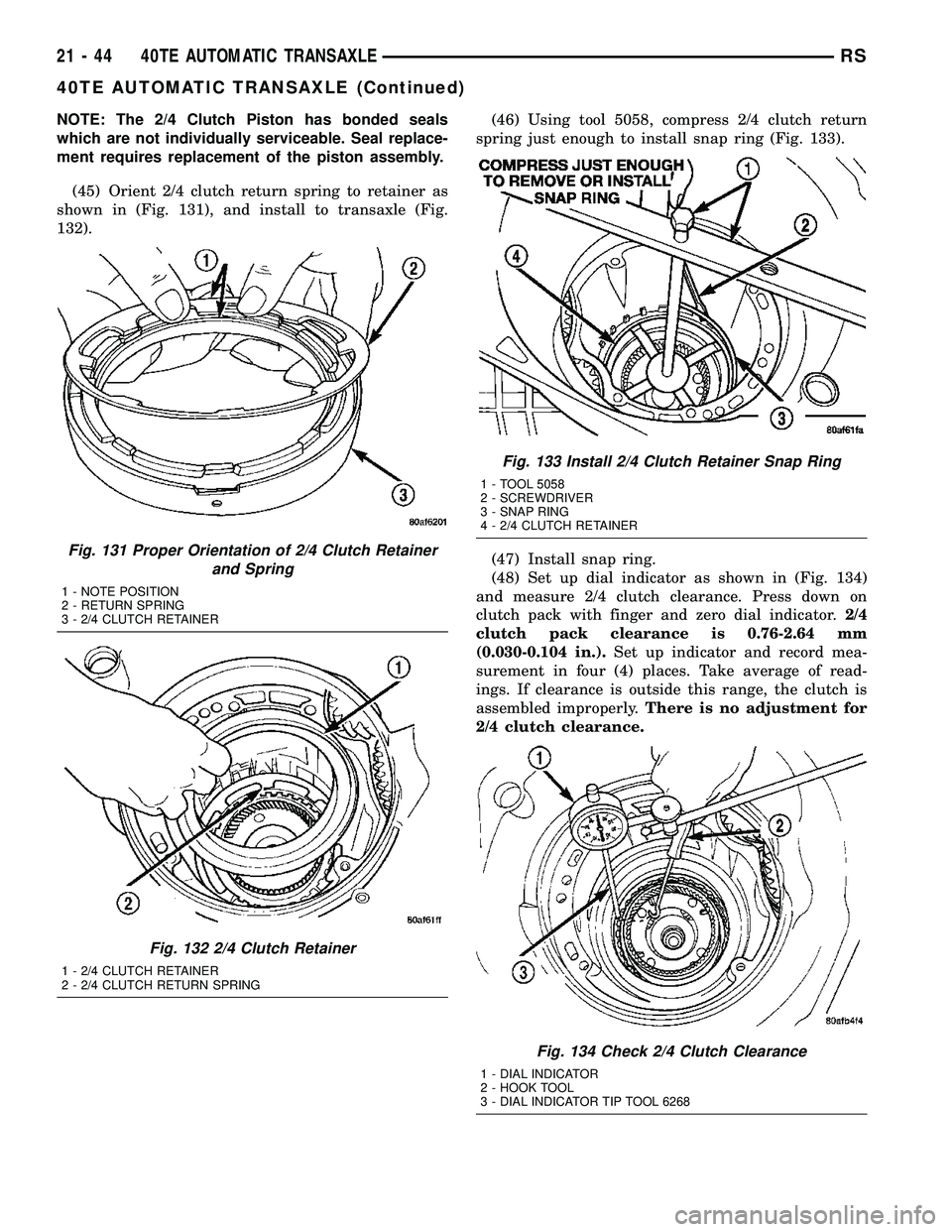
NOTE: The 2/4 Clutch Piston has bonded seals
which are not individually serviceable. Seal replace-
ment requires replacement of the piston assembly.
(45) Orient 2/4 clutch return spring to retainer as
shown in (Fig. 131), and install to transaxle (Fig.
132).(46) Using tool 5058, compress 2/4 clutch return
spring just enough to install snap ring (Fig. 133).
(47) Install snap ring.
(48) Set up dial indicator as shown in (Fig. 134)
and measure 2/4 clutch clearance. Press down on
clutch pack with finger and zero dial indicator.2/4
clutch pack clearance is 0.76-2.64 mm
(0.030-0.104 in.).Set up indicator and record mea-
surement in four (4) places. Take average of read-
ings. If clearance is outside this range, the clutch is
assembled improperly.There is no adjustment for
2/4 clutch clearance.
Fig. 131 Proper Orientation of 2/4 Clutch Retainer
and Spring
1 - NOTE POSITION
2 - RETURN SPRING
3 - 2/4 CLUTCH RETAINER
Fig. 132 2/4 Clutch Retainer
1 - 2/4 CLUTCH RETAINER
2 - 2/4 CLUTCH RETURN SPRING
Fig. 133 Install 2/4 Clutch Retainer Snap Ring
1 - TOOL 5058
2 - SCREWDRIVER
3 - SNAP RING
4 - 2/4 CLUTCH RETAINER
Fig. 134 Check 2/4 Clutch Clearance
1 - DIAL INDICATOR
2 - HOOK TOOL
3 - DIAL INDICATOR TIP TOOL 6268
21 - 44 40TE AUTOMATIC TRANSAXLERS
40TE AUTOMATIC TRANSAXLE (Continued)