Electronic control modules CHRYSLER VOYAGER 2005 Owner's Manual
[x] Cancel search | Manufacturer: CHRYSLER, Model Year: 2005, Model line: VOYAGER, Model: CHRYSLER VOYAGER 2005Pages: 2339, PDF Size: 59.69 MB
Page 304 of 2339
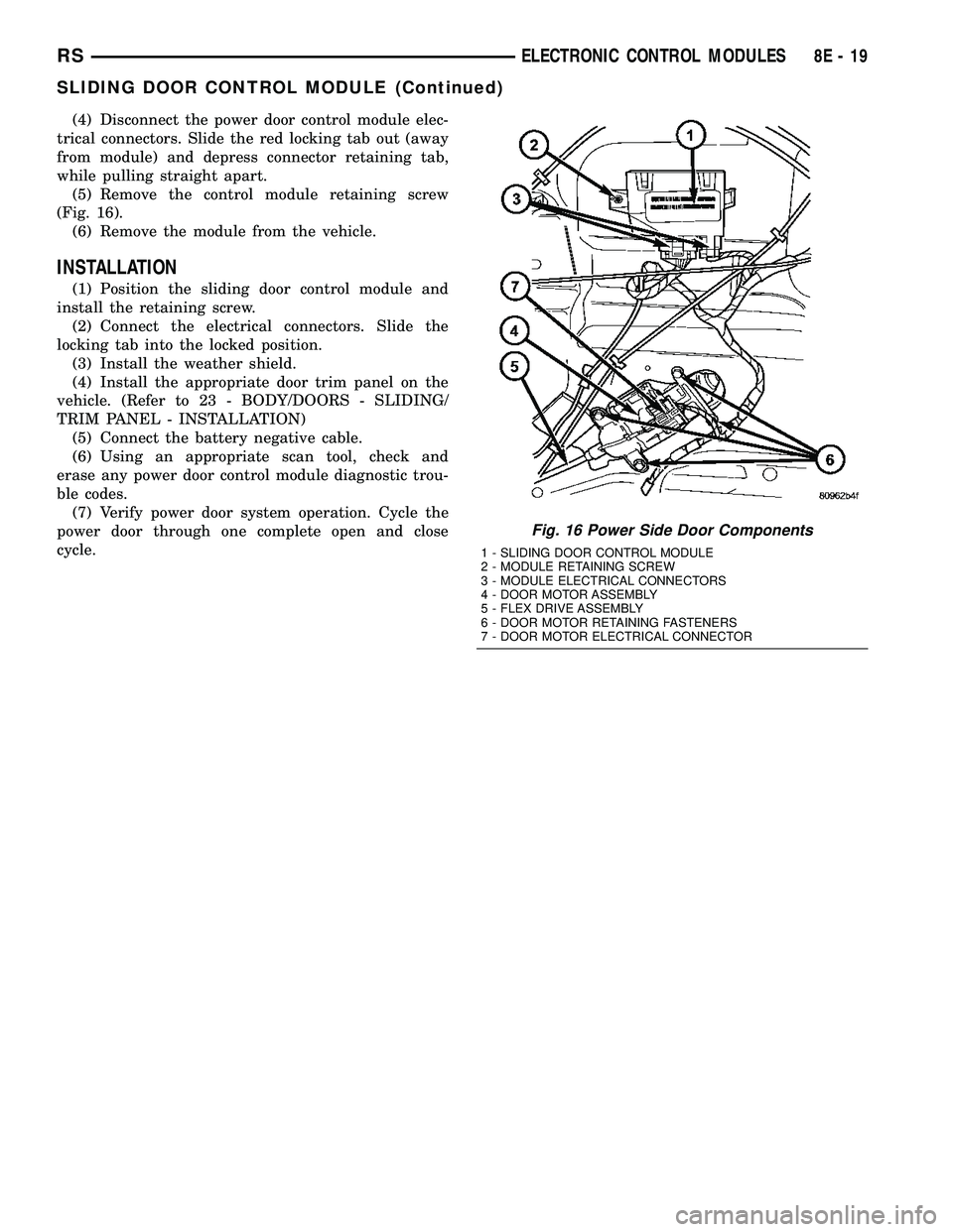
(4) Disconnect the power door control module elec-
trical connectors. Slide the red locking tab out (away
from module) and depress connector retaining tab,
while pulling straight apart.
(5) Remove the control module retaining screw
(Fig. 16).
(6) Remove the module from the vehicle.
INSTALLATION
(1) Position the sliding door control module and
install the retaining screw.
(2) Connect the electrical connectors. Slide the
locking tab into the locked position.
(3) Install the weather shield.
(4) Install the appropriate door trim panel on the
vehicle. (Refer to 23 - BODY/DOORS - SLIDING/
TRIM PANEL - INSTALLATION)
(5) Connect the battery negative cable.
(6) Using an appropriate scan tool, check and
erase any power door control module diagnostic trou-
ble codes.
(7) Verify power door system operation. Cycle the
power door through one complete open and close
cycle.
Fig. 16 Power Side Door Components
1 - SLIDING DOOR CONTROL MODULE
2 - MODULE RETAINING SCREW
3 - MODULE ELECTRICAL CONNECTORS
4 - DOOR MOTOR ASSEMBLY
5 - FLEX DRIVE ASSEMBLY
6 - DOOR MOTOR RETAINING FASTENERS
7 - DOOR MOTOR ELECTRICAL CONNECTOR
RSELECTRONIC CONTROL MODULES8E-19
SLIDING DOOR CONTROL MODULE (Continued)
Page 318 of 2339
twenty amperes or more will require a shorter charg-
ing time.
²State-Of-Charge- A completely discharged bat-
tery requires more charging time than a partially
discharged battery. Electrolyte is nearly pure water
in a completely discharged battery. At first, the
charging current (amperage) will be low. As the bat-
tery charges, the specific gravity of the electrolyte
will gradually rise.
The Conventional Battery Charging Time Table
gives an indication of the time required to charge a
typical battery at room temperature based upon the
battery state-of-charge and the charger capacity.
CONVENTIONAL BATTERY CHARGING TIME TABLE
Charging
Amperage5 Amps10
Amps20 Amps
Open Circuit
VoltageHours Charging @ 21É C (70É
F)
12.25 to 12.49 6 hours 3 hours 1.5
hours
12.00 to 12.24 10 hours 5 hours 2.5
hours
10.00 to 11.99 14 hours 7 hours 3.5
hours
Below 10.00 18 hours 9 hours 4.5
hours
OPEN-CIRCUIT VOLTAGE TEST
A battery open-circuit voltage (no load) test will
show the approximate state-of-charge of a battery.
This test can be used if no other battery tester is
available.
Before proceeding with this test, completely charge
the battery. (Refer to 8 - ELECTRICAL/BATTERY
SYSTEM/BATTERY - STANDARD PROCEDURE) for
the proper battery charging procedures.
(1) Before measuring the open-circuit voltage, the
surface charge must be removed from the battery.
Turn on the headlamps for fifteen seconds, then
allow up to five minutes for the battery voltage to
stabilize.
(2) Disconnect and isolate both battery cables, neg-
ative cable first.
(3) Using a voltmeter connected to the battery
posts (see the instructions provided by the manufac-
turer of the voltmeter), measure the open-circuit volt-
age.
See the Open-Circuit Voltage Table. This voltage
reading will indicate the battery state-of-charge, but
will not reveal its cranking capacity. If a battery has
an open-circuit voltage reading of 12.4 volts or
greater, it may be load tested to reveal its crankingcapacity. (Refer to 8 - ELECTRICAL/BATTERY SYS-
TEM/BATTERY - STANDARD PROCEDURE -
USING THE MICRO 420 BATTERY TESTER) for
the proper battery load test procedures.
OPEN CIRCUIT VOLTAGE TABLE
Open Circuit Voltage Charge Percentage
11.7 volts or less 0%
12.0 volts 25%
12.2 volts 50%
12.45 volts 75%
12.65 volts or more 100%
IGNITION-OFF DRAW TEST
The term Ignition-Off Draw (IOD) identifies a nor-
mal condition where power is being drained from the
battery with the ignition switch in the Off position. A
normal vehicle electrical system will draw from fif-
teen to twenty-five milliamperes (0.015 to 0.025
ampere) with the ignition switch in the Off position,
and all non-ignition controlled circuits in proper
working order. Up to twenty-five milliamperes are
needed to enable the memory functions for the Pow-
ertrain Control Module (PCM), digital clock, electron-
ically tuned radio, and other modules which may
vary with the vehicle equipment.
A vehicle that has not been operated for approxi-
mately twenty-one days, may discharge the battery
to an inadequate level. When a vehicle will not be
used for twenty-one days or more (stored), remove
the IOD fuse from the Integrated Power Module
(IPM). This will reduce battery discharging.
Excessive IOD can be caused by:
²Electrical items left on.
²Faulty or improperly adjusted switches.
²Faulty or shorted electronic modules and compo-
nents.
²An internally shorted generator.
²Intermittent shorts in the wiring.
If the IOD is over twenty-five milliamperes, the
problem must be found and corrected before replac-
ing a battery. In most cases, the battery can be
charged and returned to service after the excessive
IOD condition has been corrected.
(1) Verify that all electrical accessories are off.
Turn off all lamps, remove the ignition key, and close
all doors. If the vehicle is equipped with an illumi-
nated entry system or an electronically tuned radio,
allow the electronic timer function of these systems
to automatically shut off (time out). This may take
up to twenty minutes.
(2) Disconnect the battery negative cable.
RSBATTERY SYSTEM8F-13
BATTERY (Continued)
Page 326 of 2339
CHARGING
TABLE OF CONTENTS
page page
CHARGING
DESCRIPTION - CHARGING SYSTEM.......21
OPERATION - CHARGING SYSTEM.........21
DIAGNOSIS AND TESTING
ON-BOARD DIAGNOSTIC SYSTEM........22
SPECIFICATIONS
GENERATOR........................23
TORQUE............................23
SPECIFICATIONS - BATTERY
TEMPERATURE SENSOR...............23
SPECIAL TOOLS.......................24
BATTERY TEMPERATURE SENSOR
DESCRIPTION.........................24
OPERATION...........................24
REMOVAL.............................24
GENERATOR
DESCRIPTION.........................24
OPERATION...........................24REMOVAL
REMOVAL - 2.4L......................24
REMOVAL - 2.5L......................25
REMOVAL - 3.3/3.8L...................27
INSTALLATION
INSTALLATION - 2.4L..................27
INSTALLATION - 2.5L..................27
INSTALLATION - 3.3/3.8L................27
GENERATOR DECOUPLER PULLEY
DESCRIPTION.........................28
OPERATION...........................28
DIAGNOSIS AND TESTING - GENERATOR
DECOUPLER PULLEY..................28
REMOVAL.............................29
INSTALLATION.........................29
VOLTAGE REGULATOR
DESCRIPTION.........................30
OPERATION...........................30
CHARGING
DESCRIPTION - CHARGING SYSTEM
The charging system consists of:
²Generator
²Decoupler Pulley (If equipped)
²Electronic Voltage Regulator (EVR) circuitry
within the Powertrain Control Module (PCM)
²Ignition switch (refer to the Ignition System sec-
tion for information)
²Battery (refer to the Battery section for informa-
tion)
²Ambient Air Temperature (If equipped)
²Inlet Air Temperature (calculated battery tem-
perature)(If equipped)
²Voltmeter (refer to the Instrument Cluster sec-
tion for information if equipped)
²Wiring harness and connections (refer to the
Wiring section for information)
²Accessory drive belt (refer to the Cooling section
for more information)
²Battery Temperature sensor (if equipped)
OPERATION - CHARGING SYSTEM
The charging system is turned on and off with the
ignition switch. The system is on when the engine is
running and the ASD relay is energized. The ASD
relay is energized when the PCM grounds the ASD
control circuit. This voltage is connected through thePCM or IPM (intelligent power module) (if equipped)
and supplied to one of the generator field terminals
(Gen. Source +) at the back of the generator.
The generator is driven by the engine through a
serpentine belt and pulley or decoupler pulley
arrangement.
The amount of DC current produced by the gener-
ator is controlled by the EVR (field control) circuitry
contained within the PCM. This circuitry is con-
nected in series with the second rotor field terminal
and ground.
An Ambient air temperature sensor is used to cal-
culate the temperature near the battery. This tem-
perature data, along with data from monitored line
voltage (battery voltage sense circuit), is used by the
PCM to vary the battery charging rate. This is done
by cycling the ground path to control the strength of
the rotor magnetic field. The PCM then compensates
and regulates generator current output accordingly
to maintain system voltage at the targeted system
voltage based on battery temperature.
All vehicles are equipped with On-Board Diagnos-
tics (OBD). All OBD-sensed systems, including EVR
(field control) circuitry, are monitored by the PCM.
Each monitored circuit is assigned a Diagnostic Trou-
ble Code (DTC). The PCM will store a DTC in elec-
tronic memory for certain failures it detects and
illuminate the (MIL) lamp. Refer to On-Board Diag-
nostics in the Electronic Control Modules(Refer to 8 -
ELECTRICAL/ELECTRONIC CONTROL MOD-
RSCHARGING8F-21
Page 352 of 2339
HEATED SEAT SYSTEM
TABLE OF CONTENTS
page page
HEATED SEAT SYSTEM
DESCRIPTION..........................7
OPERATION............................8
DIAGNOSIS AND TESTING
HEATED SEAT SYSTEM.................8
HEATED SEAT SWITCH
DESCRIPTION..........................8
OPERATION............................9
DIAGNOSIS AND TESTING
DRIVER HEATED SEAT SWITCH..........9
REMOVAL.............................10
INSTALLATION.........................10HEATED SEAT ELEMENTS
DESCRIPTION.........................11
OPERATION...........................11
DIAGNOSIS AND TESTING
HEATED SEAT ELEMENTS..............11
REMOVAL.............................12
INSTALLATION.........................12
HEATED SEAT SENSOR
DESCRIPTION.........................13
OPERATION...........................13
DIAGNOSIS AND TESTING
HEATED SEAT SENSOR................13
HEATED SEAT SYSTEM
DESCRIPTION
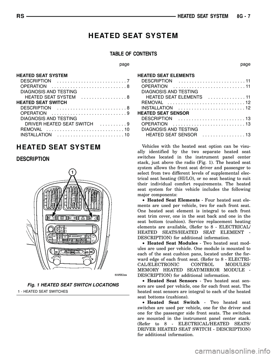
Vehicles with the heated seat option can be visu-
ally identified by the two separate heated seat
switches located in the instrument panel center
stack, just above the radio (Fig. 1). The heated seat
system allows the front seat driver and passenger to
select from two different levels of supplemental elec-
trical seat heating (HI/LO), or no seat heating to suit
their individual comfort requirements. The heated
seat system for this vehicle includes the following
major components:
²Heated Seat Elements- Four heated seat ele-
ments are used per vehicle, two for each front seat.
One heated seat element is integral to each front
seat trim cover, one in the seat back and one in the
seat bottom (cushion). Service replacement heating
elements are available, (Refer to 8 - ELECTRICAL/
HEATED SEATS/HEATED SEAT ELEMENT -
DESCRIPTION) for additional information.
²Heated Seat Modules- Two heated seat mod-
ules are used per vehicle. One module is mounted to
each of the seat cushion pans, located under the for-
ward edge of each front seat. (Refer to 8 - ELECTRI-
CAL/ELECTRONIC CONTROL MODULES/
MEMORY HEATED SEAT/MIRROR MODULE -
DESCRIPTION) for additional information.
²Heated Seat Sensors- Two heated seat sen-
sors are used per vehicle, one for each front seat. The
heated seat sensors are integral to each of the heated
seat bottoms (cushions).
²Heated Seat Switch- Two heated seat
switches are used per vehicle, one for the driver and
one for the passenger side front seats. The switches
are mounted in the instrument panel center stack.
(Refer to 8 - ELECTRICAL/HEATED SEATS/
DRIVER HEATED SEAT SWITCH - DESCRIPTION)
for additional information.
Fig. 1 HEATED SEAT SWITCH LOCATIONS
1 - HEATED SEAT SWITCHES
RSHEATED SEAT SYSTEM8G-7
Page 353 of 2339

Hard wired circuitry connects the heated seat sys-
tem components to each other through the electrical
system of the vehicle. These circuits may be con-
nected to each other, to the vehicle electrical system
and to the heated seat system components through
the use of a combination of soldered splices and
splice block connectors. Refer to the appropriate wir-
ing information for complete circuit schematic or con-
nector pin-out information.
OPERATION
The heated seat system components operate on
battery current received through a fuse in the Inte-
grated Power Module (IPM) on a fused ignition
switch output (run) circuit from the Body Control
Module (BCM). The system will only operate when
the ignition switch is in the On position. The heated
seat system will be turned Off automatically when-
ever the ignition switch is turned to any position
except On. Also, the heated seat system will not oper-
ate when the surface temperature of the seat cushion
cover at either heated seat sensor is above the
designed temperature set points of the system.
DIAGNOSIS AND TESTING
HEATED SEAT SYSTEM
The most efficient means of diagnosing the heated
seat system is by individual component. For diagno-
sis of a specific component refer to the following:
²Heated seat module, (Refer to 8 - ELECTRICAL/
ELECTRONIC CONTROL MODULES/MEMORY
HEATED SEAT/MIRROR MODULE - DIAGNOSIS
AND TESTING).
²Heated seat elements, (Refer to 8 - ELECTRI-
CAL/HEATED SEATS/HEATED SEAT ELEMENT -
DIAGNOSIS AND TESTING).
²Heated seat switch, (Refer to 8 - ELECTRICAL/
HEATED SEATS/DRIVER HEATED SEAT SWITCH
- DIAGNOSIS AND TESTING).
²Heated seat sensor, (Refer to 8 - ELECTRICAL/
HEATED SEATS/HEATED SEAT SENSOR - DIAG-
NOSIS AND TESTING).
Refer to the appropriate wiring information for
complete circuit schematic or connector pin-out infor-
mation.
HEATED SEAT SWITCH
DESCRIPTION
The heated seat switches are mounted in the
instrument panel center bezel (Fig. 2). The two three-
position rocker-type switches, one switch for each
front seat, are incorporated into one large switch
assembly that also includes the hazard, rear window
wiper and washer switches. Each heated seat switch
provides a resistor multiplexed signal to its respec-
tive Heated Seat Module (HSM) through separate
hard wired circuits. Each switch has an Off, Low,
and High position so that both the driver and the
front seat passenger can select a preferred seat heat-
ing mode. Each switch has two Light-Emitting
Diodes (LED) which light to indicate that the heater
for the seat is turned on.
The heated seat switches and their LEDs cannot
be repaired. If either switch or LED is faulty or dam-
aged, the entire switch assembly must be replaced.
Fig. 2 HEATED SEAT SWITCH LOCATION
1 - HEATED SEAT SWITCHES
8G - 8 HEATED SEAT SYSTEMRS
HEATED SEAT SYSTEM (Continued)
Page 357 of 2339
1&4). There should be continuity. If OK, (Refer to 8 -
ELECTRICAL/ELECTRONIC CONTROL MOD-
ULES/MEMORY HEATED SEAT/MIRROR MOD-
ULE - DIAGNOSIS AND TESTING) for complete
system testing procedures. If not OK, install a
replacement heated seat cushion element, (Refer to 8
- ELECTRICAL/HEATED SEATS/HEATED SEAT
ELEMENT - INSTALLATION).
SEAT BACK ELEMENT
(1) From under the vehicle, remove the appropri-
ate seats four retaining nuts.
(2) From inside the vehicle, pull the seat up and
off the mounting studs and lay it back, up against
one of the rear seats.
(3) Locate the heated seat module, attached to the
bottom of the seat cushion pan. Remove the heated
seat module from the seat cushion pan. Do not dis-
connect the electrical connectors at this time.
(4) Locate and disconnect the gray 2-way electrical
connector, connected to the heated seat module.
(5) Check for continuity between the two circuit
cavities of the 2-way wire harness connector. There
should be continuity. If OK, (Refer to 8 - ELECTRI-
CAL/ELECTRONIC CONTROL MODULES/MEM-
ORY HEATED SEAT/MIRROR MODULE -
DIAGNOSIS AND TESTING) for complete system
testing procedures. If not OK, install a replacement
heated seat back element, (Refer to 8 - ELECTRI-
CAL/HEATED SEATS/HEATED SEAT ELEMENT -
INSTALLATION).
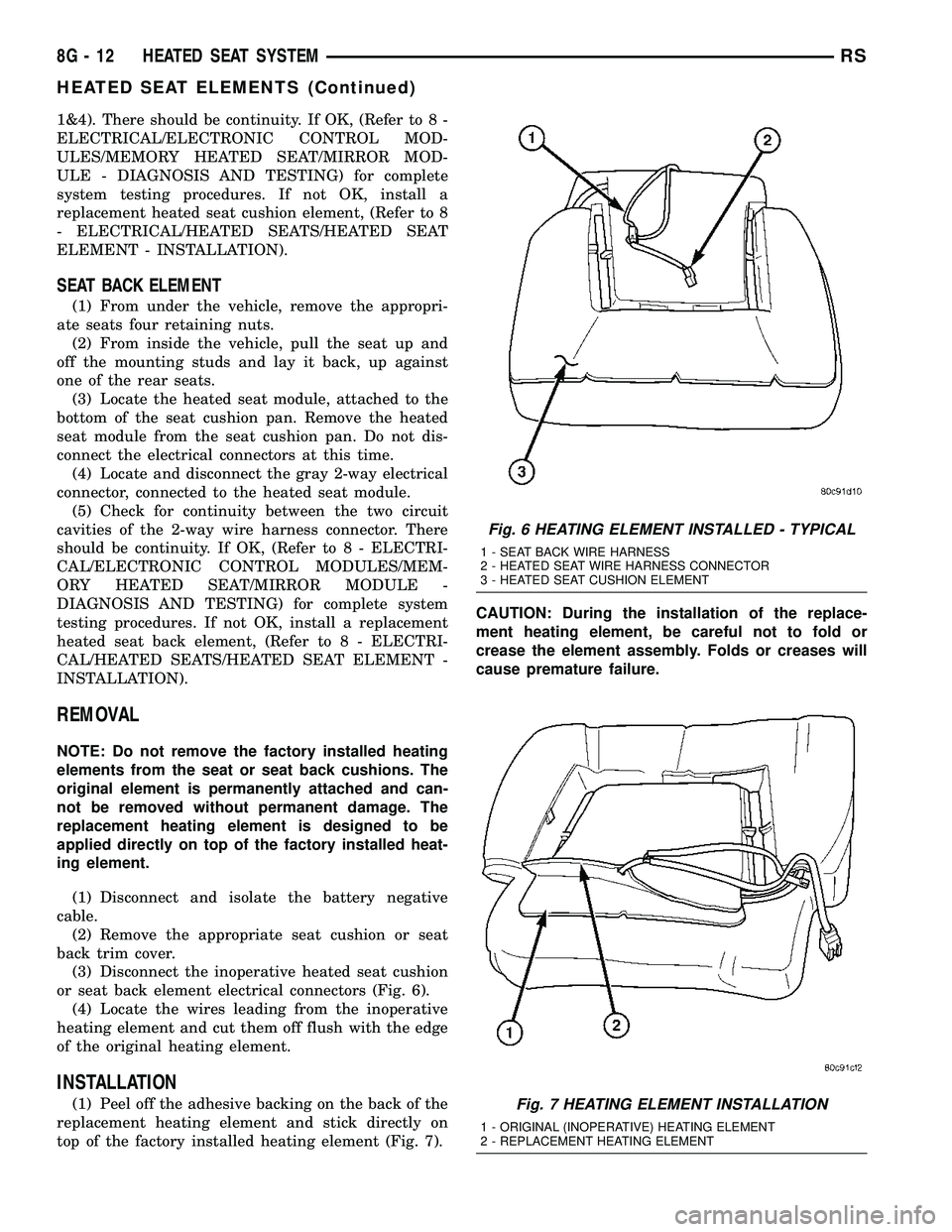
REMOVAL
NOTE: Do not remove the factory installed heating
elements from the seat or seat back cushions. The
original element is permanently attached and can-
not be removed without permanent damage. The
replacement heating element is designed to be
applied directly on top of the factory installed heat-
ing element.
(1) Disconnect and isolate the battery negative
cable.
(2) Remove the appropriate seat cushion or seat
back trim cover.
(3) Disconnect the inoperative heated seat cushion
or seat back element electrical connectors (Fig. 6).
(4) Locate the wires leading from the inoperative
heating element and cut them off flush with the edge
of the original heating element.
INSTALLATION
(1) Peel off the adhesive backing on the back of the
replacement heating element and stick directly on
top of the factory installed heating element (Fig. 7).CAUTION: During the installation of the replace-
ment heating element, be careful not to fold or
crease the element assembly. Folds or creases will
cause premature failure.
Fig. 6 HEATING ELEMENT INSTALLED - TYPICAL
1 - SEAT BACK WIRE HARNESS
2 - HEATED SEAT WIRE HARNESS CONNECTOR
3 - HEATED SEAT CUSHION ELEMENT
Fig. 7 HEATING ELEMENT INSTALLATION
1 - ORIGINAL (INOPERATIVE) HEATING ELEMENT
2 - REPLACEMENT HEATING ELEMENT
8G - 12 HEATED SEAT SYSTEMRS
HEATED SEAT ELEMENTS (Continued)
Page 361 of 2339

HORN SYSTEM TEST
CONDITION POSSIBLE CAUSE CORRECTION
HORN SOUNDS CONTINUOUSLY.
NOTE: IMMEDIATELY UNPLUG HORN
RELAY IN THE IPM.(1) HORN RELAY
INOPERATIVE.(1) REPLACE RELAY.
(2) HORN CONTROL
CIRCUIT TO RELAY
SHORTED TO GROUND.(2) CHECK TERMINAL 85 IN IPM FOR
CONTINUITY TO GROUND. IF
CONTINUITY TO GROUND INDICATES:
(A) STEERING WHEEL HORN SWITCH/
LEAD SHORTED TO GROUND.
(B) WIRING HARNESS SHORTED TO
GROUND. FIND THE SHORT AND
REPAIR AS NECESSARY.
(3) PINCHED HORN SWITCH
WIRE UNDER DRIVER
AIRBAG MODULE.(3) REPLACE DRIVER AIRBAG TRIM
COVER.
(4) HORN SWITCH
INOPERATIVE.(4) REPLACE DRIVER AIRBAG TRIM
COVER.
(5) CLOCKSPRING
INOPERATIVE.(5) REPLACE CLOCKSPRING.
(6) FRONT CONTROL
MODULE INOPERATIVE.(6) REFER TO ELECTRONIC CONTROL
MODULES/FRONT CONTROL MODULE.
HORN SOUND INTERMITTENTLY AS
THE STEERING WHEEL IS TURNED.(1) HORN RELAY CONTROL
CIRCUIT X3 IS SHORTED TO
GROUND INSIDE STEERING
COLUMN OR WHEEL.(1) REMOVE DRIVER AIRBAG AND/OR
WHEEL. CHECK FOR RUBBING OR
LOOSE WIRE/CONNECTOR, REPAIR AS
NECESSARY.
(2) PINCHED HORN SWITCH
WIRE UNDER DRIVER
AIRBAG MODULE.(2) REPLACE DRIVER AIRBAG TRIM
COVER.
(3) HORN SWITCH
INOPERATIVE.(3) REPLACE DRIVER AIRBAG TRIM
COVER.
(4) CLOCKSPRING
INOPERATIVE.(4) REPLACE CLOCKSPRING.
HORN DOES NOT SOUND (1) CHECK FUSE 8 IN
INTELLIGENT POWER
MODULE.(1) REPLACE FUSE IF BLOWN REPAIR
AS NECESSARY.
(2) NO VOLTAGE AT HORN
RELAY TERMINALS 30 & 86,
AND FUSE IS OK.(2) NO VOLTAGE, REPAIR THE CIRCUIT
AS NECESSARY.
(3) OPEN CIRCUIT FROM
TERMINAL 85 OF THE HORN
RELAY TO HORN SWITCH,
X3 CIRCUIT.(3) REPAIR CIRCUIT AS NECESSARY.
(4) HORN INOPERATIVE OR
DAMAGED.(4) CHECK VOLTAGE AT HORN WHEN
HORN SWITCH IS PRESSED. IF NO
VOLTAGE, REPLACE HORN.
(5) HORN SWITCH
INOPERATIVE.(5) REPLACE DRIVER AIRBAG TRIM
COVER.
8H - 2 HORNRS
HORN SYSTEM (Continued)
Page 362 of 2339

CONDITION POSSIBLE CAUSE CORRECTION
(6) CLOCKSPRING
INOPERATIVE.(6) REPLACE CLOCKSPRING.
(7) FRONT CONTROL
MODULE INOPERATIVE.(7) REFER TO ELECTRONIC CONTROL
MODULES/FRONT CONTROL MODULE.
FUSE BLOWS WHEN HORN SOUNDS (1) SHORT CIRCUIT IN
HORN OR HORN WIRING.(1) REMOVE HORN RELAY, CHECK
FOR SHORTED HORN OR HORN
WIRING. DISCONNECT HORN WIRE
HARNESS TO ISOLATE SHORT AND
REPAIR AS NECESSARY.
(2) CLOCKSPRING
INOPERATIVE.(2) REPLACE CLOCKSPRING.
FUSE BLOWS WITHOUT BLOWING
HORN(1) SHORT CIRCUIT. (1) REMOVE RELAY, INSTALL NEW
FUSE, IF FUSE DOES NOT BLOW
REPLACE HORN RELAY. IF FUSE
BLOWS WITH RELAY REMOVED,
CHECK FOR SHORT TO GROUND
WITH OHMMETER ON CIRCUIT
BETWEEN TERMINALS 30 & 86 AND
THE FUSE TERMINAL. REPAIR AS
NECESSARY.
(2) CLOCKSPRING
INOPERATIVE.(2) REPLACE CLOCKSPRING.
HORN
DIAGNOSIS AND TESTING
HORN
HORN
(1) Disconnect wire connector at horn.
(2) Using a voltmeter, connect one lead to ground
terminal and the other lead to the positive wire ter-
minal (Fig. 1).
(3) Depress the horn switch, battery voltage
should be present.
(4) If no voltage, refer toHORNS WILL NOT
SOUND. If voltage is OK, go to step Step 5.
(5) Using ohmmeter, test ground wire for continu-
ity to ground.
(6) If no ground repair as necessary.
(7) If wires test OK and horn does not sound,
replace horn.
HORNS SOUND CONTINUOUSLY
CAUTION: Continuous sounding of horns may
cause relay to fail.
The horn switch (membrane) sometimes can be the
cause without the switch being depressed.(1) Remove the horn relay from the intelligent
power module.
(2)
Using a continuity tester, test continuity from the
X3 cavity of the horn relay to ground. Refer to the
appropriate wiring information. The wiring information
includes wiring diagrams, proper wire and connector
repair procedures, details of wire harness routing and
retention, connector pin-out information and location
views for the various wire harness connectors, splices
and grounds.
(a)If continuity is detected, proceed to step Step 3.
(b) If NO continuity, replace the horn relay.
(3) Remove the airbag trim cover from the steering
wheel and disengage horn connector.
(4) Install horn relay into Integrated Power Mod-
ule (IPM).
(a)
If horn does not sound, replace airbag trim
cover.
(b) If horn sounds, repair grounded X3 circuit
from IPM to clockspring in the steering column.
HORNS WILL NOT SOUND
Check horn fuse#8intheIPM. If fuse is blown,
check for a shorted switch in the airbag module. and
refer to FUSE BLOWN section. If fuse is OK, refer to
FUSE OK section.
FUSE BLOWN
(1) Verify condition of battery terminals and volt-
age, (Refer to 8 - ELECTRICAL/BATTERY SYSTEM
RSHORN8H-3
HORN SYSTEM (Continued)
Page 412 of 2339
The compass unit will also compensate for magne-
tism the vehicle may acquire during normal use.
However, avoid placing anything magnetic directly on
the roof of the vehicle. Magnetic mounts for an
antenna, a repair order hat, or a funeral procession
flag can exceed the compensating ability of the com-
pass unit if placed on the roof panel. The use of mag-
netic tools on the fasteners that hold the overhead
console assembly to the roof header can also affect
compass operation. If the compass operation is
erratic and roof magnetization is suspected (Refer to
8 - ELECTRICAL/OVERHEAD CONSOLE - STAN-
DARD PROCEDURE - COMPASS DEMAGNETIZ-
ING).
DESCRIPTION - TEMPERATURE
All overhead consoles include temperature informa-
tion. The temperature displays the outside ambient
temperature in whole degrees. The temperature dis-
play can be toggled from Fahrenheit to Celsius by
selecting the desired U.S./Metric option from the cus-
tomer programmable features. The displayed temper-
ature is not an instant reading of conditions, but an
average temperature. It may take the temperature
display several minutes to respond to a major tem-
perature change, such as driving out of a heated
garage into winter temperatures.
When the ignition switch is turned to the Off posi-
tion, the last displayed temperature reading stays in
the electronic control modules (CMTC, EVIC) mem-
ory. When the ignition switch is turned to the On
position again, the electronic module will display the
memory temperature for one minute; then update the
display to the current average temperature reading
within five minutes.
The temperature function is supported by an ambi-
ent temperature sensor. The sensor is mounted near
the front and center of the vehicle, and is hard wired
to the Powertrain Control Module (PCM). The PCM
sends temperature status messages to the module
over the Programmable Communication Interface
(PCI) data bus circuit.
DIAGNOSIS AND TESTING
OVERHEAD CONSOLE
Any diagnosis of the overhead console should
begin with the use of the DRB IIItdiagnostic
tool. For information on the use of the DRB
IIIt, refer to the appropriate Diagnostic Proce-
dures information.If the problem with the overhead console is an
inaccurate or dashed (- -) display, refer to SELF-DI-
AGNOSTIC TEST. If the problem with the overhead
console is incorrect Vacuum Fluorescent Display
(VFD) dimming levels, use a DRB IIItscan tool and
the proper diagnostic procedures information to test
for the correct dimming message inputs being
received from the Body Control Module (BCM) or
Front Control Module (FCM) over the Programmable
Communications Interface (PCI) data bus circuit. If
the problem is a no-display condition, use the follow-
ing procedures.
Inspect the related wiring harness connectors for
broken, bent, pushed out, or corroded terminals.
Refer to the appropriate wiring information.
(1) Check the fused B(+) fuse in the integrated
power module. If OK, go to Step 2. If not OK, repair
the shorted circuit or component as required and
replace the faulty fuse.
(2) Check for battery voltage at the fused B(+) fuse
in the integrated power module. If OK, go to Step 3.
If not OK, repair the open fused B(+) circuit to the
fused B(+) fuse in the integrated power module as
required.
(3) Check the fused ignition switch output (run/
start) fuse in the integrated power module. If OK, go
to Step 4. If not OK, repair the shorted circuit or
component as required and replace the faulty fuse.
(4) Turn the ignition switch to the On position.
Check for battery voltage at the fused ignition switch
output (run/start) fuse in the integrated power mod-
ule. If OK, go to Step 5. If not OK, repair the open
fused ignition switch output (run/start) circuit to the
ignition switch as required.
(5) Turn the ignition switch to the Off position.
Disconnect and isolate the battery negative cable.
Remove the overhead console. Check for continuity
between the ground circuit cavity of the roof wire
harness connector for the electronics module and a
good ground. There should be continuity. If OK, go to
Step 6. If not OK, repair the open ground circuit as
required.
(6) Connect the battery negative cable. Check for
battery voltage at the fused B(+) circuit cavity of the
roof wire harness connector for the electronics mod-
ule. If OK, go to Step 7. If not OK, repair the open
fused B(+) circuit to the fused B(+) fuse in the inte-
grated power module as required.
(7) Turn the ignition switch to the On position.
Check for battery voltage at the fused ignition switch
output (run/start) circuit cavity of the roof wire har-
ness connector for the electronics module. If OK,
refer to SELF-DIAGNOSTIC TEST. If not OK, repair
the open fused ignition switch output (run/start) cir-
cuit to the fuse in the integrated power module as
required.
RSOVERHEAD CONSOLE8M-3
OVERHEAD CONSOLE (Continued)
Page 420 of 2339
NOTE: If a new CMTC module has been installed,
the compass will have to be calibrated and the vari-
ance set. (Refer to 8 - ELECTRICAL/OVERHEAD
CONSOLE - STANDARD PROCEDURE - COMPASS
CALIBRATION).
UNIVERSAL TRANSMITTER
DESCRIPTION
A Universal Transmitter transceiver is available on
some vehicles. The universal transmitter transceiver
is integral to the Electronic Vehicle Information Cen-
ter (EVIC) and the Compass Mini-Trip Computer
(CMTC) modules, which are located in the overhead
console. The only visible component of the universal
transmitter are the three transmitter push buttons
centered between the modules push buttons located
just rearward of the display screen in the overhead
console. The three universal transmitter push but-
tons are identified with one, two or three light indi-
cators so that they can be easily identified.
Each of the three universal transmitter push but-
tons controls an independent radio transmitter chan-
nel. Each of these three channels can be trained to
transmit a different radio frequency signal for the
remote operation of garage door openers, motorized
gate openers, home or office lighting, security sys-
tems or just about any other device that can be
equipped with a radio receiver in the 286 to 399
MegaHertz (MHz) frequency range for remote opera-
tion. The universal transmitter is capable of operat-
ing systems using either rolling code or non-rolling
code technology.
The electronics module displays messages and a
small house-shaped icon with one, two or three dots
corresponding to the three transmitter buttons to
indicate the status of the universal transmitter. The
EVIC messages are:
²Cleared Channels- Indicates that all of the
transmitter codes stored in the universal transmitter
have been successfully cleared.
²Training- Indicates that the universal trans-
mitter is in its transmitter learning mode.
²Trained- Indicates that the universal transmit-
ter has successfully acquired a new transmitter code.
²Transmit- Indicates that a trained universal
transmitter button has been depressed and that the
universal transmitter is transmitting.
The universal transmitter cannot be repaired, and
is available for service only as a unit with the EVIC
or CMTC modules. If any of these components is
faulty or damaged, the complete EVIC or CMTC
module must be replaced.
DIAGNOSIS AND TESTING
UNIVERSAL TRANSMITTER
If both the Universal Transmitter and the Elec-
tronic Vehicle Information Center (EVIC) are inoper-
ative, (Refer to 8 - ELECTRICAL/OVERHEAD
CONSOLE/ELECTRONIC VEHICLE INFO CENTER
- DIAGNOSIS AND TESTING). If the Universal
Transmitter is inoperative, but the EVIC is operating
normally, retrain the Transmitter with a known good
transmitter (Refer to 8 - ELECTRICAL/OVERHEAD
CONSOLE/UNIVERSAL TRANSMITTER - STAN-
DARD PROCEDURE - SETTING TRANSMITTER
CODES). If the unit is still inoperative, test the uni-
versal transmitter with the Radio Frequency Detec-
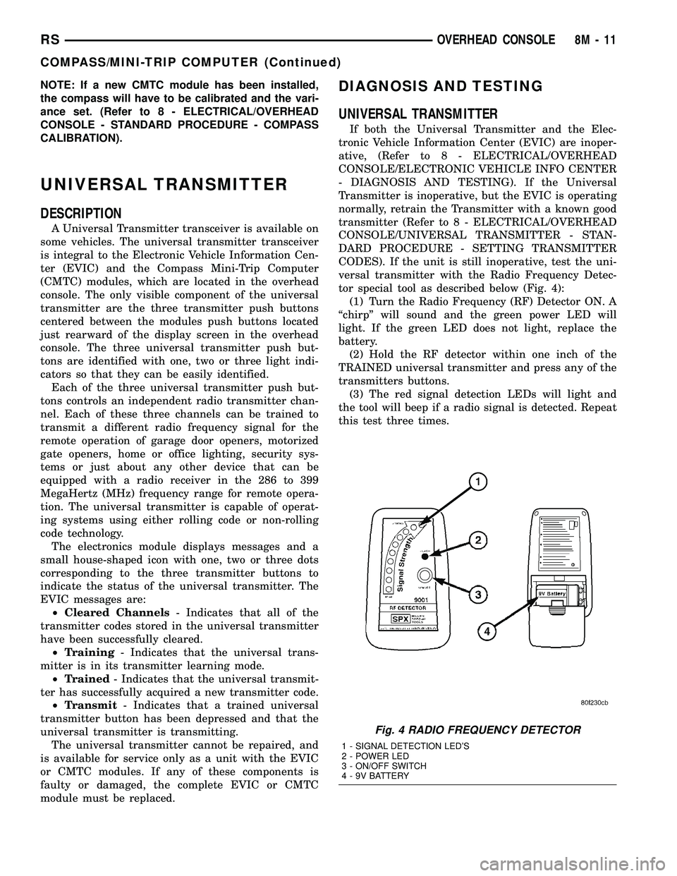
tor special tool as described below (Fig. 4):
(1) Turn the Radio Frequency (RF) Detector ON. A
ªchirpº will sound and the green power LED will
light. If the green LED does not light, replace the
battery.
(2) Hold the RF detector within one inch of the
TRAINED universal transmitter and press any of the
transmitters buttons.
(3) The red signal detection LEDs will light and
the tool will beep if a radio signal is detected. Repeat
this test three times.
Fig. 4 RADIO FREQUENCY DETECTOR
1 - SIGNAL DETECTION LED'S
2 - POWER LED
3 - ON/OFF SWITCH
4 - 9V BATTERY
RSOVERHEAD CONSOLE8M-11
COMPASS/MINI-TRIP COMPUTER (Continued)