wheel CHRYSLER VOYAGER 2005 Service Manual
[x] Cancel search | Manufacturer: CHRYSLER, Model Year: 2005, Model line: VOYAGER, Model: CHRYSLER VOYAGER 2005Pages: 2339, PDF Size: 59.69 MB
Page 2111 of 2339
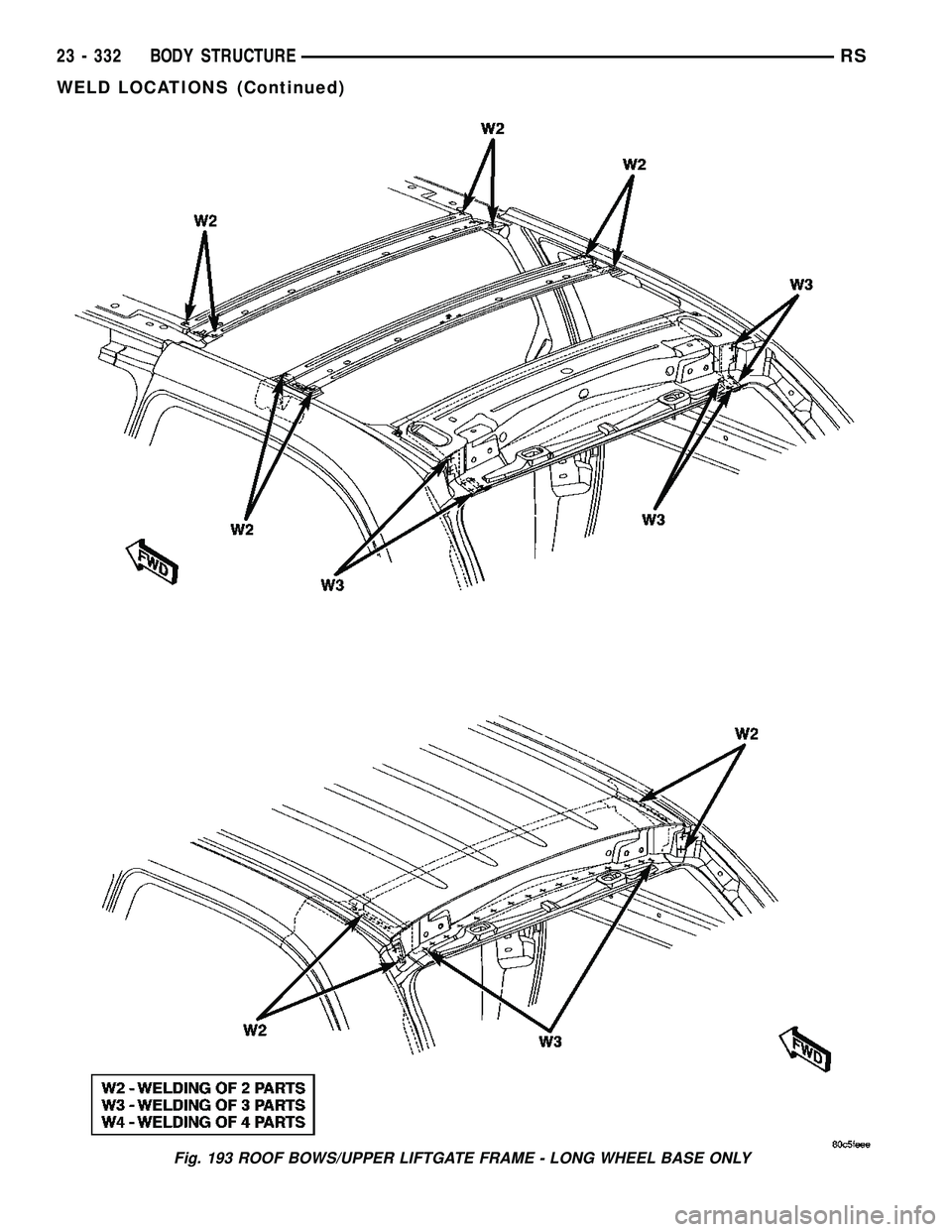
Fig. 193 ROOF BOWS/UPPER LIFTGATE FRAME - LONG WHEEL BASE ONLY
23 - 332 BODY STRUCTURERS
WELD LOCATIONS (Continued)
Page 2112 of 2339
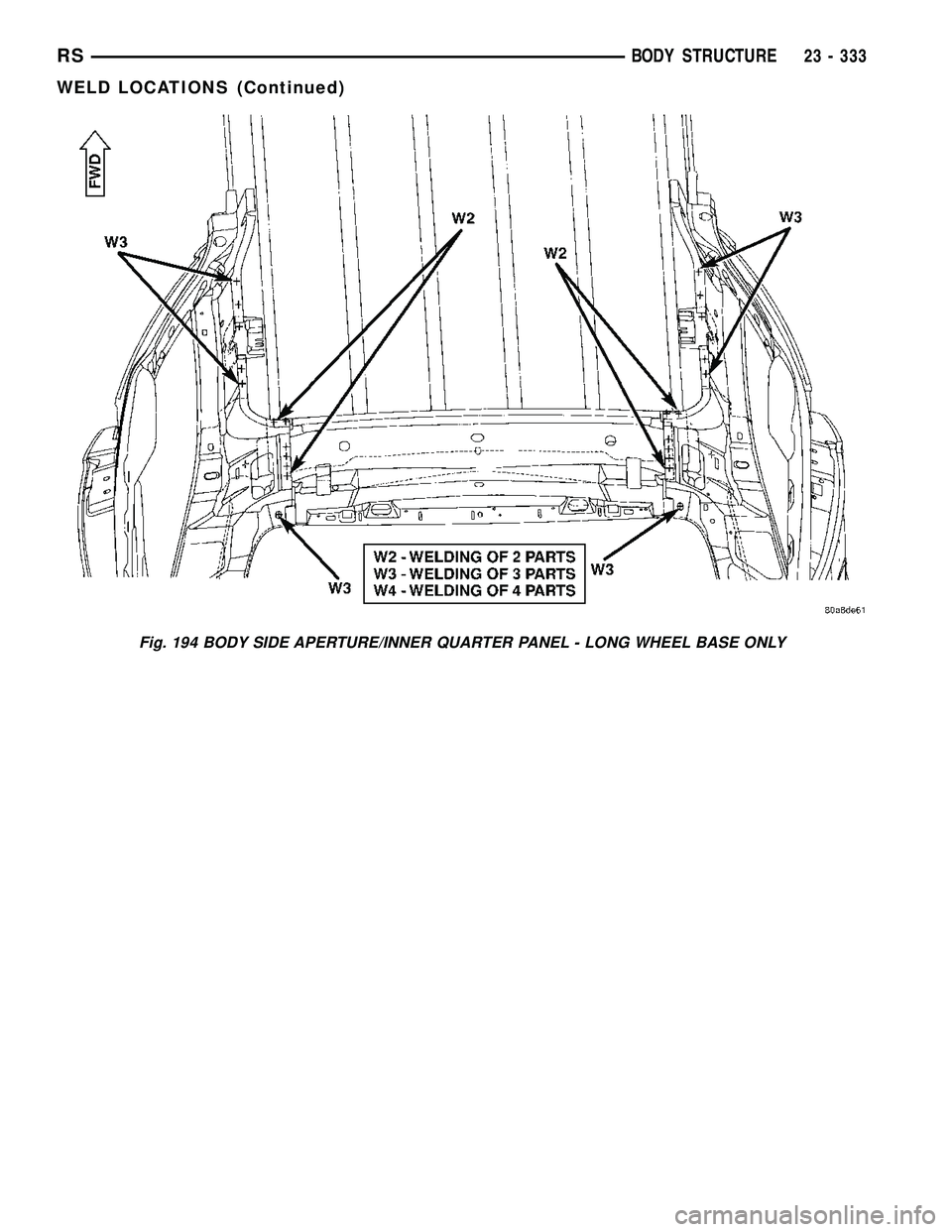
Fig. 194 BODY SIDE APERTURE/INNER QUARTER PANEL - LONG WHEEL BASE ONLY
RSBODY STRUCTURE23 - 333
WELD LOCATIONS (Continued)
Page 2113 of 2339
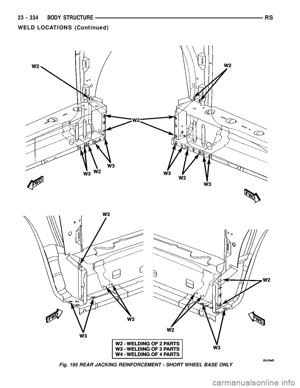
Fig. 195 REAR JACKING REINFORCEMENT - SHORT WHEEL BASE ONLY
23 - 334 BODY STRUCTURERS
WELD LOCATIONS (Continued)
Page 2114 of 2339
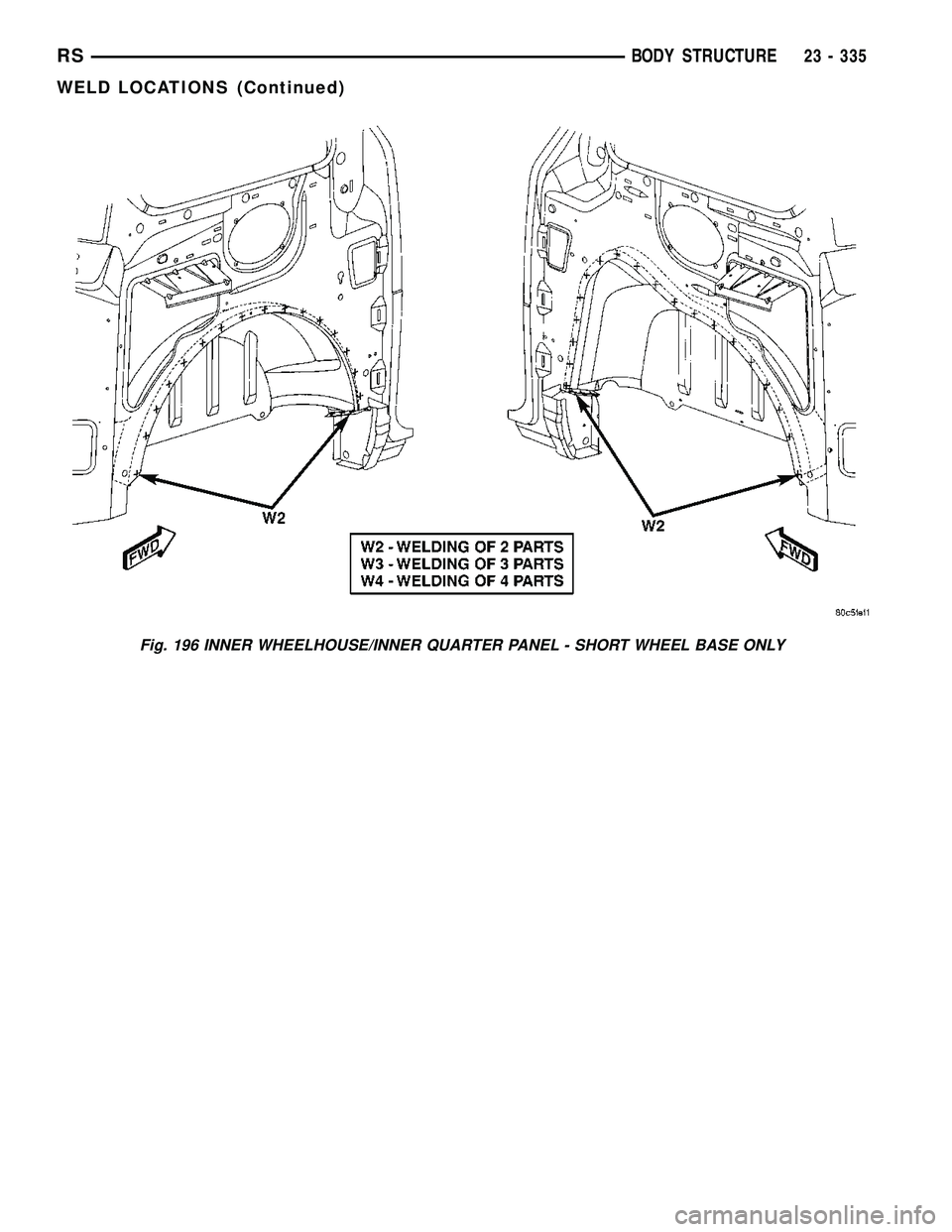
Fig. 196 INNER WHEELHOUSE/INNER QUARTER PANEL - SHORT WHEEL BASE ONLY
RSBODY STRUCTURE23 - 335
WELD LOCATIONS (Continued)
Page 2115 of 2339
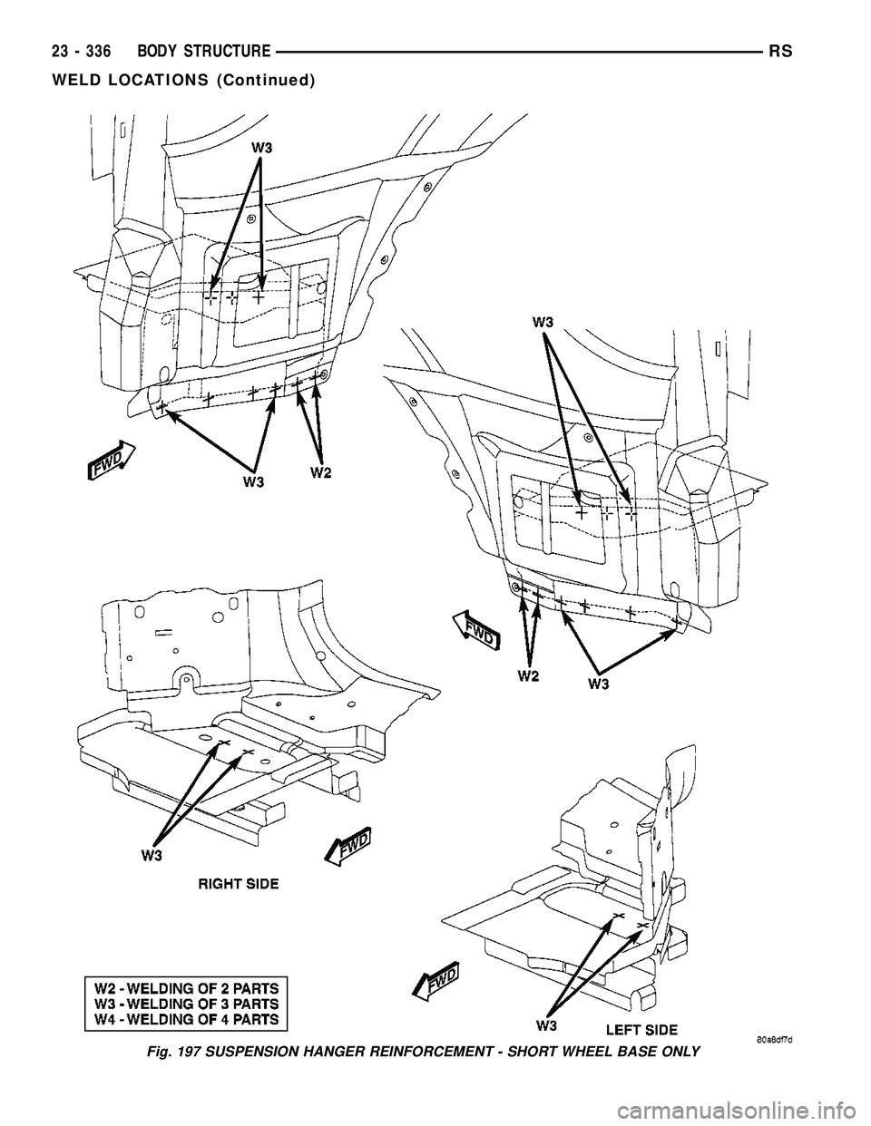
Fig. 197 SUSPENSION HANGER REINFORCEMENT - SHORT WHEEL BASE ONLY
23 - 336 BODY STRUCTURERS
WELD LOCATIONS (Continued)
Page 2116 of 2339
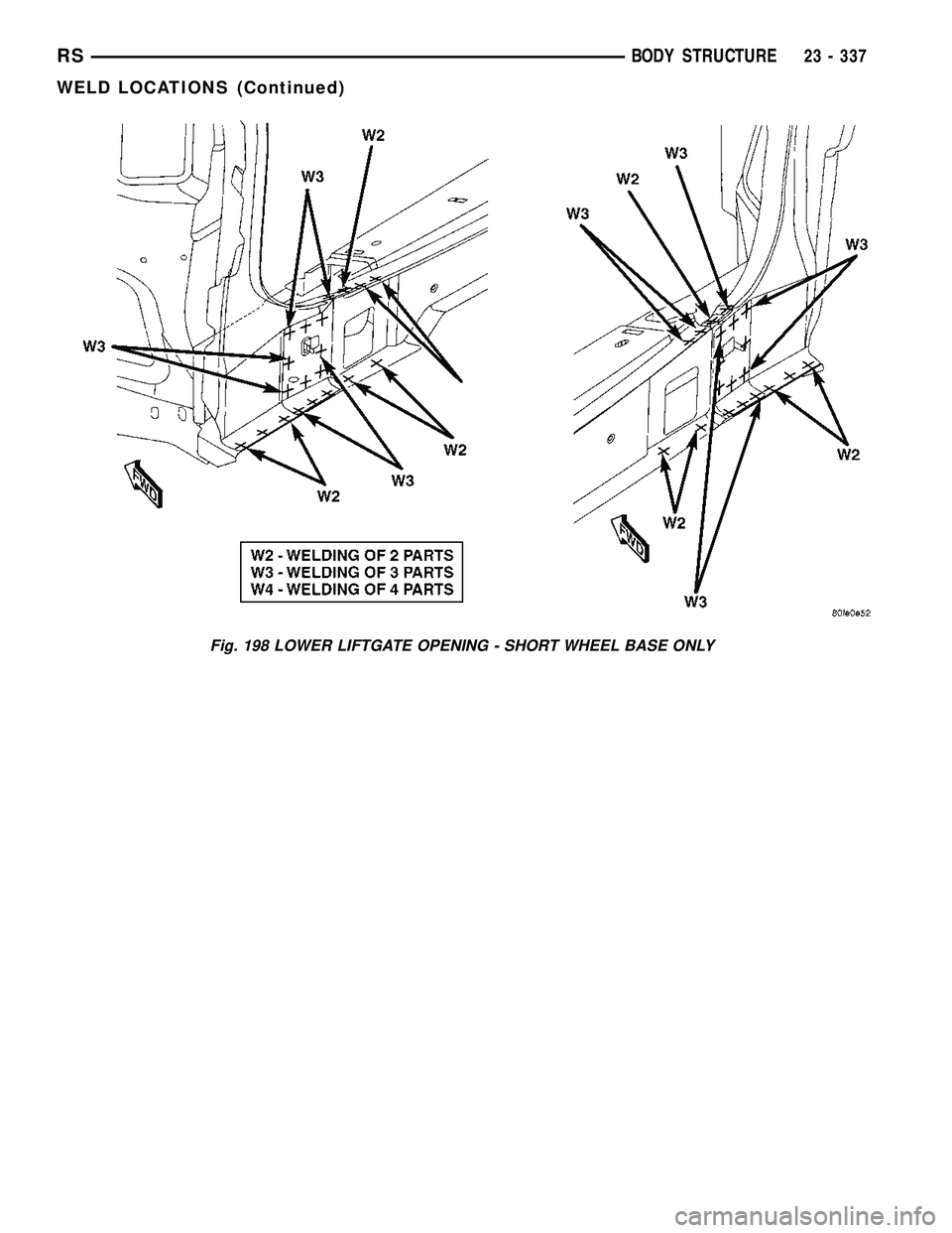
Fig. 198 LOWER LIFTGATE OPENING - SHORT WHEEL BASE ONLY
RSBODY STRUCTURE23 - 337
WELD LOCATIONS (Continued)
Page 2117 of 2339

Fig. 199 ROOF PANEL/ROOF RAIL - SHORT WHEEL BASE ONLY
23 - 338 BODY STRUCTURERS
WELD LOCATIONS (Continued)
Page 2118 of 2339
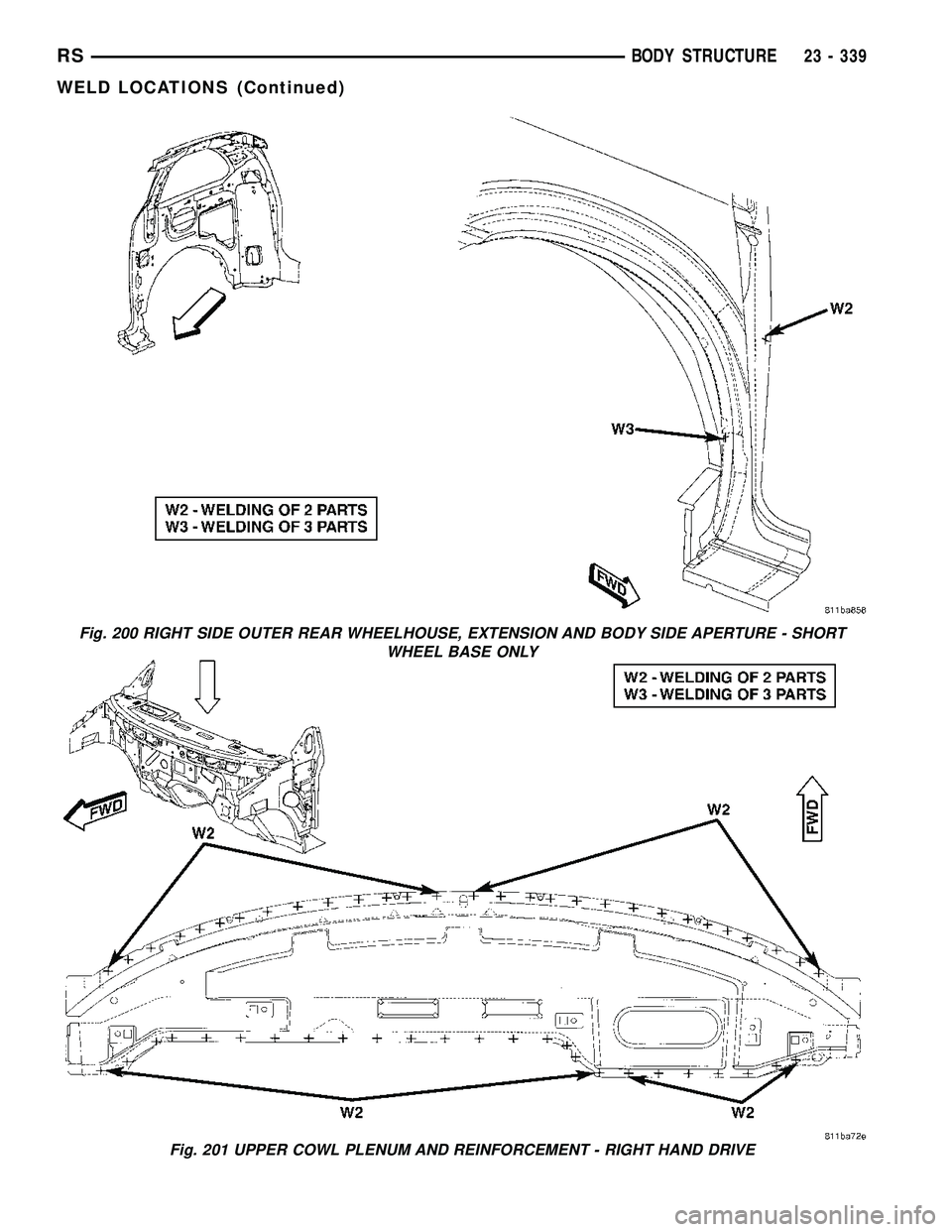
Fig. 200 RIGHT SIDE OUTER REAR WHEELHOUSE, EXTENSION AND BODY SIDE APERTURE - SHORT
WHEEL BASE ONLY
Fig. 201 UPPER COWL PLENUM AND REINFORCEMENT - RIGHT HAND DRIVE
RSBODY STRUCTURE23 - 339
WELD LOCATIONS (Continued)
Page 2165 of 2339
clutch plate into contact with the clutch pulley and
drives the compressor shaft. When the coil is not
energized, the pulley freewheels on the clutch hub
bearing, which is part of the pulley.
A zener diode is connected in parallel with the
clutch electromagnetic coil. This diode controls the
dissipation of voltage induced into the coil windings
by the collapsing of the electromagnetic fields that
occurs when the compressor clutch is disengaged.
The zener diode dissipates this induced voltage by
regulating a current path to ground. This arrange-
ment serves to protect other circuits and components
from potentially damaging voltage spikes in the vehi-
cle electrical system that might occur if the voltage
induced in the clutch coil windings could not be dis-
sipated.
The compressor clutch engagement is controlled by
several components: the heater-A/C controls in the
passenger compartment, the A/C pressure transducer
on the liquid line, the evaporator temperature sensor
on the expansion valve for automatic temperature
control (ATC) system or on the HVAC housing for
manual temperature control (MTC) system, the Pow-
ertrain Control Module (PCM) in the engine compart-
ment, and the compressor clutch relay in the
Integrated Power Module (IPM). The PCM may delay
compressor clutch engagement for up to thirty sec-
onds (Refer to 8 - ELECTRICAL/ELECTRONIC
CONTROL MODULES/POWERTRAIN CONTROL
MODULE - DESCRIPTION - PCM OPERATION).
DIAGNOSIS AND TESTING
A/C COMPRESSOR CLUTCH COIL
The air conditioning compressor clutch coil electri-
cal circuit is controlled by the powertrain control
module (PCM) through the A/C compressor clutch
relay, which is located in the integrated power mod-
ule (IPM) in the engine compartment. Begin testing
of a suspected compressor clutch coil problem by per-
forming the preliminary checks.
PRELIMINARY CHECKS
(1) If the compressor clutch will not engage, verify
the refrigerant charge level (Refer to 24 - HEATING
& AIR CONDITIONING/PLUMBING - FRONT/RE-
FRIGERANT - DIAGNOSIS AND TESTING -
REFRIGERANT CHARGE LEVEL). If the refriger-
ant charge level is OK, go to Step 2. If the refriger-
ant charge level is not OK, adjust the refrigerant
charge as required.
(2) If the A/C compressor clutch still will not
engage, disconnect the wire harness connector for the
A/C pressure transducer and check for battery cur-
rent at the connector with the engine running and
the A/C-heater control set to the A/C mode. If OK, go
to TESTS. If not OK, refer to Body Diagnostic Proce-
dures to perform further diagnosis.
TESTS
(1) Verify the battery state of charge (Refer to 8 -
ELECTRICAL/BATTERY SYSTEM/BATTERY -
DIAGNOSIS AND TESTING).
(2) Connect an ammeter (0 to 10 ampere scale
selected) in series with the clutch coil feed terminal.
Connect a voltmeter (0 to 20 volt scale selected) to
measure voltage across the battery and the clutch
coil.
(3) With the heater-A/C control in the A/C mode
and the blower at low speed, start the engine and
allow it to run at a normal idle speed.
(4) The compressor clutch should engage immedi-
ately, and the clutch coil voltage should be within
two volts of the battery voltage. If the coil voltage is
not within two volts of battery voltage, test the
clutch coil feed circuit for excessive voltage drop. If
the compressor clutch does not engage, refer to Body
Diagnostic Procedures to perform further diagnosis.
(5) For the acceptable A/C clutch coil current draw
specificationsrefer to 24 - HEATING & AIR CONDI-
TIONING - SPECIFICATIONS. Specifications apply
for a work area temperature of 21É C (70É F). If volt-
age is more than 12.5 volts, add electrical loads by
turning on electrical accessories until voltage reads
below 12.5 volts.
(a) If the compressor clutch coil current reading
is zero, the coil is open and must be replaced.
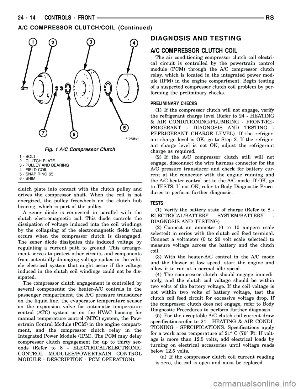
Fig. 1 A/C Compressor Clutch
1 - BOLT
2 - CLUTCH PLATE
3 - PULLEY AND BEARING
4 - FIELD COIL
5 - SNAP RING (2)
6 - SHIM
24 - 14 CONTROLS - FRONTRS
A/C COMPRESSOR CLUTCH/COIL (Continued)
Page 2171 of 2339
REMOVAL
WARNING: ON VEHICLES EQUIPPED WITH AIR-
BAGS, DISABLE THE AIRBAG SYSTEM BEFORE
ATTEMPTING ANY STEERING WHEEL, STEERING
COLUMN, OR INSTRUMENT PANEL COMPONENT
DIAGNOSIS OR SERVICE. DISCONNECT AND ISO-
LATE THE BATTERY NEGATIVE (GROUND) CABLE,
THEN WAIT TWO MINUTES FOR THE AIRBAG SYS-
TEM CAPACITOR TO DISCHARGE BEFORE PER-
FORMING FURTHER DIAGNOSIS OR SERVICE. THIS
IS THE ONLY SURE WAY TO DISABLE THE AIRBAG
SYSTEM. FAILURE TO TAKE THE PROPER PRE-
CAUTIONS COULD RESULT IN ACCIDENTAL AIR-
BAG DEPLOYMENT AND POSSIBLE PERSONAL
INJURY.
(1) Disconnect and isolate the battery negative
cable.
(2) Remove the center bezel from the instrument
panel (Refer to 23 - BODY/INSTRUMENT PANEL/
INSTRUMENT PANEL CENTER BEZEL -
REMOVAL).
(3) Place the instrument panel center bezel unit
face down on a suitable work surface. Take the
proper precautions to protect the center bezel from
cosmetic damage.
(4) If the vehicle is equipped with the optional
Automatic Temperature Control (ATC) system, dis-
connect the infrared sensor jumper harness connector
from the receptacle on the back of the A/C-heater
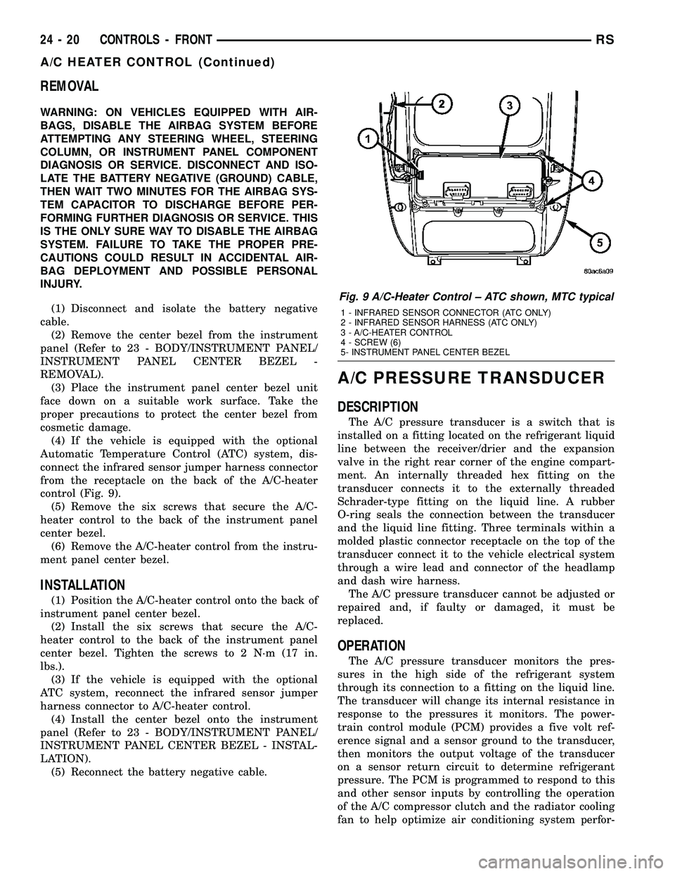
control (Fig. 9).
(5) Remove the six screws that secure the A/C-
heater control to the back of the instrument panel
center bezel.
(6) Remove the A/C-heater control from the instru-
ment panel center bezel.
INSTALLATION
(1) Position the A/C-heater control onto the back of
instrument panel center bezel.
(2) Install the six screws that secure the A/C-
heater control to the back of the instrument panel
center bezel. Tighten the screws to 2 N´m (17 in.
lbs.).
(3) If the vehicle is equipped with the optional
ATC system, reconnect the infrared sensor jumper
harness connector to A/C-heater control.
(4) Install the center bezel onto the instrument
panel (Refer to 23 - BODY/INSTRUMENT PANEL/
INSTRUMENT PANEL CENTER BEZEL - INSTAL-
LATION).
(5) Reconnect the battery negative cable.
A/C PRESSURE TRANSDUCER
DESCRIPTION
The A/C pressure transducer is a switch that is
installed on a fitting located on the refrigerant liquid
line between the receiver/drier and the expansion
valve in the right rear corner of the engine compart-
ment. An internally threaded hex fitting on the
transducer connects it to the externally threaded
Schrader-type fitting on the liquid line. A rubber
O-ring seals the connection between the transducer
and the liquid line fitting. Three terminals within a
molded plastic connector receptacle on the top of the
transducer connect it to the vehicle electrical system
through a wire lead and connector of the headlamp
and dash wire harness.
The A/C pressure transducer cannot be adjusted or
repaired and, if faulty or damaged, it must be
replaced.
OPERATION
The A/C pressure transducer monitors the pres-
sures in the high side of the refrigerant system
through its connection to a fitting on the liquid line.
The transducer will change its internal resistance in
response to the pressures it monitors. The power-
train control module (PCM) provides a five volt ref-
erence signal and a sensor ground to the transducer,
then monitors the output voltage of the transducer
on a sensor return circuit to determine refrigerant
pressure. The PCM is programmed to respond to this
and other sensor inputs by controlling the operation
of the A/C compressor clutch and the radiator cooling
fan to help optimize air conditioning system perfor-
Fig. 9 A/C-Heater Control ± ATC shown, MTC typical
1 - INFRARED SENSOR CONNECTOR (ATC ONLY)
2 - INFRARED SENSOR HARNESS (ATC ONLY)
3 - A/C-HEATER CONTROL
4 - SCREW (6)
5- INSTRUMENT PANEL CENTER BEZEL
24 - 20 CONTROLS - FRONTRS
A/C HEATER CONTROL (Continued)