coolant level CHRYSLER VOYAGER 2005 Owner's Guide
[x] Cancel search | Manufacturer: CHRYSLER, Model Year: 2005, Model line: VOYAGER, Model: CHRYSLER VOYAGER 2005Pages: 2339, PDF Size: 59.69 MB
Page 1616 of 2339
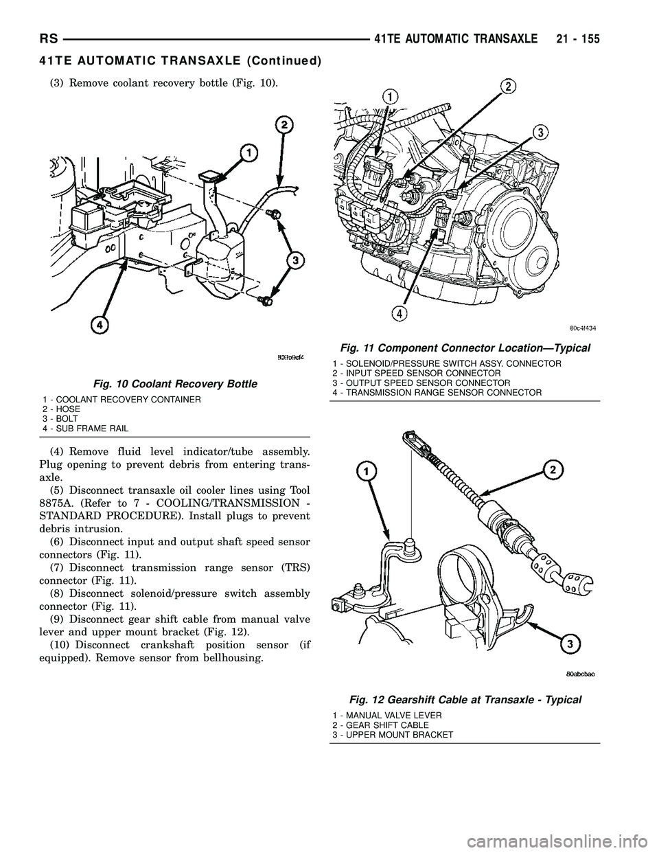
(3) Remove coolant recovery bottle (Fig. 10).
(4) Remove fluid level indicator/tube assembly.
Plug opening to prevent debris from entering trans-
axle.
(5) Disconnect transaxle oil cooler lines using Tool
8875A. (Refer to 7 - COOLING/TRANSMISSION -
STANDARD PROCEDURE). Install plugs to prevent
debris intrusion.
(6) Disconnect input and output shaft speed sensor
connectors (Fig. 11).
(7) Disconnect transmission range sensor (TRS)
connector (Fig. 11).
(8) Disconnect solenoid/pressure switch assembly
connector (Fig. 11).
(9) Disconnect gear shift cable from manual valve
lever and upper mount bracket (Fig. 12).
(10) Disconnect crankshaft position sensor (if
equipped). Remove sensor from bellhousing.
Fig. 10 Coolant Recovery Bottle
1 - COOLANT RECOVERY CONTAINER
2 - HOSE
3 - BOLT
4 - SUB FRAME RAIL
Fig. 11 Component Connector LocationÐTypical
1 - SOLENOID/PRESSURE SWITCH ASSY. CONNECTOR
2 - INPUT SPEED SENSOR CONNECTOR
3 - OUTPUT SPEED SENSOR CONNECTOR
4 - TRANSMISSION RANGE SENSOR CONNECTOR
Fig. 12 Gearshift Cable at Transaxle - Typical
1 - MANUAL VALVE LEVER
2 - GEAR SHIFT CABLE
3 - UPPER MOUNT BRACKET
RS41TE AUTOMATIC TRANSAXLE21 - 155
41TE AUTOMATIC TRANSAXLE (Continued)
Page 2152 of 2339
HEATING & AIR CONDITIONING
TABLE OF CONTENTS
page page
HEATING & AIR CONDITIONING
DESCRIPTION
ENGINE COOLING SYSTEM
REQUIREMENTS.......................1
HEATER AND AIR CONDITIONER..........1
MANUAL SINGLE ZONE.................2
MANUAL DUAL ZONE...................2
MANUAL THREE ZONE..................2
AUTOMATIC TEMPERATURE CONTROL....3
OPERATION
HEATER AND AIR CONDITIONER..........4
MANUAL SINGLE ZONE.................4
MANUAL DUAL ZONE...................5
MANUAL THREE ZONE..................5AUTOMATIC TEMPERATURE CONTROL....5
DIAGNOSIS AND TESTING
A/C COOL DOWN TEST.................6
A/C PERFORMANCE TEST...............7
HEATER PERFORMANCE TEST..........10
SPECIFICATIONS
A/C SYSTEM.........................11
CONTROLS - FRONT.....................13
CONTROLS - REAR......................33
DISTRIBUTION - FRONT...................42
DISTRIBUTION - REAR....................56
PLUMBING - FRONT.....................64
PLUMBING - REAR......................98
CABIN HEATER........................113
HEATING & AIR
CONDITIONING
DESCRIPTION
ENGINE COOLING SYSTEM REQUIREMENTS
To maintain the performance level of the heating,
ventilation and air conditioning (HVAC) system, the
engine cooling system must be properly maintained.
The use of a bug screen is not recommended. Any
obstructions in front of the radiator or condenser will
reduce the performance of the air conditioning and
engine cooling systems.
The engine cooling system includes the radiator,
thermostat, radiator hoses and the engine coolant
pump. Refer to Cooling for more information before
opening or attempting any service to the engine cool-
ing system.
HEATER AND AIR CONDITIONER
A manually controlled single zone type heating-air
conditioning system, manually controlled dual zone
type heating-air conditioning system, manually con-
trolled three zone type heating-air conditioning sys-
tem or an automatic controlled three zone type
heating-air conditioning system is available on this
model.
All vehicles are equipped with a common heater,
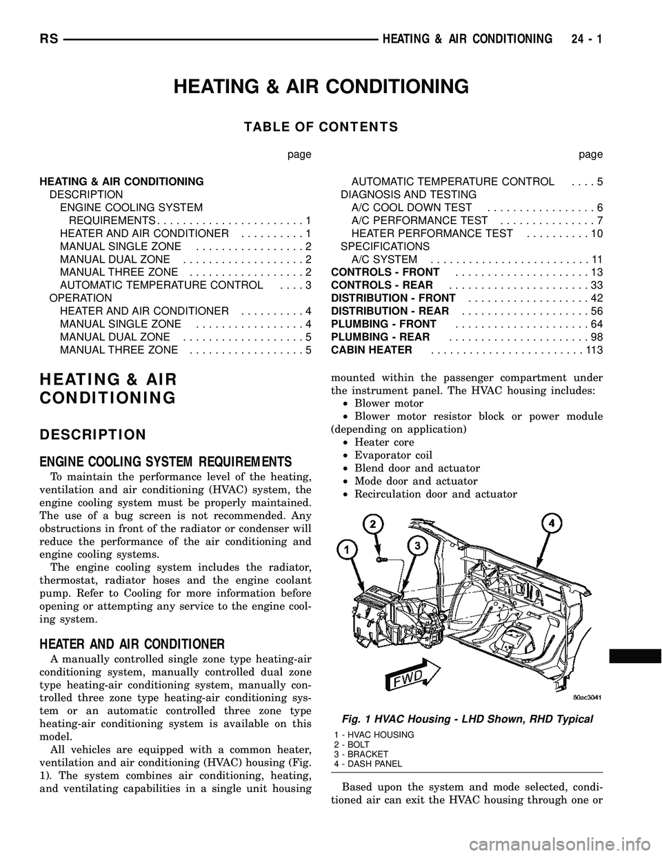
ventilation and air conditioning (HVAC) housing (Fig.
1). The system combines air conditioning, heating,
and ventilating capabilities in a single unit housingmounted within the passenger compartment under
the instrument panel. The HVAC housing includes:
²Blower motor
²Blower motor resistor block or power module
(depending on application)
²Heater core
²Evaporator coil
²Blend door and actuator
²Mode door and actuator
²Recirculation door and actuator
Based upon the system and mode selected, condi-
tioned air can exit the HVAC housing through one or
Fig. 1 HVAC Housing - LHD Shown, RHD Typical
1 - HVAC HOUSING
2 - BOLT
3 - BRACKET
4 - DASH PANEL
RSHEATING & AIR CONDITIONING24-1
Page 2154 of 2339
²a rotary adjustment knob for temperature.
²a rotary adjustment for fan speed control.
AUTOMATIC TEMPERATURE CONTROL
Two different automatic temperature control (ATC)
heating-A/C systems are available for this model
depending on the market.
The Dual-Zone ATC system allows the driver and
front occupants to each select individual comfort tem-
peratures.
The Three-Zone ATC system allows both the driver
and front occupants and the rear intermediate occu-
pants to select individual comfort temperatures.
NOTE: Individual comfort temperatures are the per-
ceived temperature level at the individual seating
areas, NOT the actual passenger compartment air
temperature.
The ATC system includes a particulate air filter.
The filter element is the same size as the A/C evap-
orator to ensure ample capacity. A door at the base of
the HVAC housing below the glove box provides easy
access to the filter element.
The ATC computer utilizes integrated circuitry and
information carried on the programmable communi-
cations interface (PCI) data bus network to monitor
many sensors and switch inputs throughout the vehi-
cle. In response to those inputs, the internal circuitry
and programming of the ATC computer allow it to
control electronic functions and features of the ATC
system. The inputs to the ATC computer are:
²Vehicle Speed/Engine RPM± The ATC com-
puter monitors engine rpm, vehicle speed and mani-
fold absolute pressure information from the
powertrain control module (PCM).
²Coolant Temperature± ATC computer moni-
tors coolant temperature received from the PCM and
converts it to degrees Fahrenheit.
²Ambient Temperature± ATC computer moni-
tors ambient temperature from the compass mini trip
computer (CMTC) and converts it to degrees Fahren-
heit.
²Engine Miscellaneous Sensor Status±ATC
computer monitors A/C disable information from the
PCM.
²Refrigerant Pressure± ATC computer moni-
tors barometric pressure, intake air temperature,
high side pressure and methanol content as broad-
cast by the PCM.
²Door Ajar Status± The ATC computer moni-
tors driver front door, passenger front door, left rear
door, right rear door and liftgate ajar information, as
identified by the body control module (BCM), to
determine if all in-car temperatures should be main-
tained.²Dimming± The ATC computer monitors dim-
ming status from the BCM to determine the required
level of brightness and will dim accordingly.
²Vehicle Odometer± The ATC computer moni-
tors the vehicle odometer information from the BCM
to prevent flashing the vacuum-flourescent (VF) dig-
ital display icons if the manual motor calibration or
manual cool down tests have failed. Flashing of the
display icons will cease when the vehicle odometer is
greater than 3 miles.
²English/Metric± The ATC computer monitors
the English/Metric information broadcast by the
CMTC. The set temp displays for both the front and
rear control heads will be set accordingly.
²Vehicle Identification Number± The ATC
computer monitors the last eight characters of the
VIN broadcast by the PCM and compares it to the
information stored in EEPROM. If it is different, the
new number will be stored over the old one and a
motor calibration shall be initiated.
²A/C System Information± The ATC computer
will send a message for evaporator temperature too
low, fan blower relay status, evaporator sensor fail-
ure, rear window defogger relay and A/C select.
FRONT CONTROL PANEL
The front A/C-heater control and integral computer
is mounted in the instrument panel and contains:
²a power button which allows the system to be
completely turned off. The display is blank when the
system is off.
²a rocker switch that selects a cool-down rate.
LO-AUTO or HI-AUTO are displayed when the sys-
tem is in automatic operation.
²three rocker switches that select comfort temper-
atures from 15É to 30É C (59É to 85É F), which are
shown in the VF digital display. If the set temp is 15É
C (59É F) and the down button is pressed, the set
temp value will become 13É C (55É F) but the display
will show LO. If the set temp is 29É C (85É F) and the
up button is pressed, the set temp value will become
32É C (90É F) but the display will show HIGH. Tem-
peratures can be displayed in either metric or Fahr-
enheit, which is controlled from the overhead console.
²an air conditioning button that allows the com-
pressor to be turned off. A Snowflake symbol is illu-
minated when air conditioning is on, whether under
manual or automatic control.
²an air recirculation button. A Recirculation sym-
bol appears in the display when the button is
pressed, or when the system exceeds 80 percent recir-
culated air under automatic control due to high air
conditioning demand.
²a rear window defogger on/off switch. A graphic
symbol shows when the defroster is on.
RSHEATING & AIR CONDITIONING24-3
HEATING & AIR CONDITIONING (Continued)
Page 2161 of 2339
Condition Possible Causes Correction
The low side pressure is too
low, and the high side
pressure is too high.1. Restricted refrigerant flow
through the refrigerant lines.1. See Liquid Line, Suction Line and Discharge
Line in this group. Inspect the refrigerant lines for
kinks, tight bends or improper routing. Correct
the routing or replace the refrigerant line, if
required.
2. Restricted refrigerant flow
through the A/C expansion
valve.2. See A/C Expansion Valve in this group.
Replace the valve, if required.
3. Restricted refrigerant flow
through the A/C condenser.3. See A/C Condenser in this group. Replace the
restricted condenser, if required.
HEATER PERFORMANCE TEST
WARNING: REVIEW SAFETY PRECAUTIONS AND
WARNINGS IN THIS GROUP BEFORE PERFORMING
THIS PROCEDURE (Refer to 24 - HEATING & AIR
CONDITIONING/PLUMBING - WARNING).
Check the coolant level, drive belt tension, radiator
air flow and fan operation. Start engine and allow to
warm up to normal operating temperature.
WARNING: DO NOT REMOVE RADIATOR CAP
WHEN ENGINE IS HOT, PERSONAL INJURY CAN
RESULT.
If vehicle has been run recently, wait 15 minutes
before removing the radiator cap. Place a rag overthe cap and turn it to the first safety stop. Allow
pressure to escape through the overflow tube. When
the system pressure stabilizes, remove the cap com-
pletely.
MAXIMUM HEATER OUTPUT: TEST AND ACTION
Engine coolant is provided to the heater system by
two heater hoses. With the engine idling at normal
operating temperature, set the temperature control
to maximum heat, the mode control to the floor posi-
tion, and the blower in the highest speed position.
Using a test thermometer, check the temperature of
the air being discharged from the floor outlets. Com-
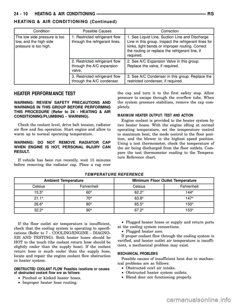
pare the test thermometer reading to the Tempera-
ture Reference chart.
TEMPERATURE REFERENCE
Ambient Temperature Minimum Floor Outlet Temperature
Celsius Fahrenheit Celsius Fahrenheit
15.5É 60É 62.2É 144É
21.1É 70É 63.8É 147É
26.6É 80É 65.5É 150É
32.2É 90É 67.2É 153É
If the floor outlet air temperature is insufficient,
check that the cooling system is operating to specifi-
cations (Refer to 7 - COOLING/ENGINE - DIAGNO-
SIS AND TESTING). Both heater hoses should be
HOT to the touch (the coolant return hose should be
slightly cooler than the supply hose). If the coolant
return hose is much cooler than the supply hose,
locate and repair the engine coolant flow obstruction
in heater system.
OBSTRUCTED COOLANT FLOW Possible locations or causes
of obstructed coolant flow are as follows:
²Pinched or kinked heater hoses.
²Improper heater hose routing.²Plugged heater hoses or supply and return ports
at the cooling system connections.
²Plugged heater core.
If proper coolant flow through the cooling system is
verified, and heater outlet air temperature is insuffi-
cient, a mechanical problem may exist.
MECHANICAL PROBLEMS
Possible causes of insufficient heat due to mechan-
ical problems are as follows:
²Obstructed cowl air intake.
²Obstructed heater system outlets.
²Blend door not functioning properly.
24 - 10 HEATING & AIR CONDITIONINGRS
HEATING & AIR CONDITIONING (Continued)
Page 2253 of 2339

(5) Install the rear evaporator line extension onto
the expansion valve (Refer to 24 - HEATING & AIR
CONDITIONING/PLUMBING - REAR/EVAPORA-
TOR - INSTALLATION - EVAPORATOR LINE
EXTENSION).
(6) Install the foam insulator wrap over the rear
expansion valve.
(7) Install the rear HVAC housing (Refer to 24 -
HEATING & AIR CONDITIONING/DISTRIBUTION/
HVAC HOUSING - INSTALLATION).
(8) Run the HVAC Cooldown Test to verify proper
operation.
HEATER CORE
DESCRIPTION
The rear heater core is located near the front of
the rear HVAC housing, behind the right rear wheel
house. It is a heat exchanger made of rows of tubes
and fins. One end of the core is fitted with a molded
plastic tank that includes integral heater core inlet
and outlet nipples. The rear heater core can be ser-
viced without removing the rear HVAC housing from
the vehicle.
OPERATION
Engine coolant is circulated through underbody
heater hoses to the rear heater core at all times. As
the coolant flows through the rear heater core, heat
removed from the engine is transferred to the heater
core fins and tubes. Air directed through the heater
core picks up the heat from the heater core fins. The
rear blend door allows control of the rear heater out-
put air temperature by controlling how much of the
air flowing through the rear HVAC housing is
directed through the heater core.
The rear heater core cannot be repaired and, if
faulty or damaged, it must be replaced.
STANDARD PROCEDURE
REAR HEATER CORE FILLING
In its final installed position, the rear heater core
is positioned higher than the radiator fill cap. There-
fore, when the cooling system is drained and refilled,
gravity will not refill the heater core with coolant to
the proper level. This may result in two problems:1.
Insufficient coolant level in the engine cooling sys-
tem, which may result in engine overheating.2.Air
entrapped within the rear heater core, which may
result in insufficient rear heater performance. There
are two methods that may be employed to prevent
these problems:1.Pre-filling of the rear heater core.
2.Thermal cycling of the engine cooling system. Fol-lowing are descriptions of both prevention methods,
as well as a method to verify rear heater perfor-
mance.
WARNING: REFER TO THE APPLICABLE WARN-
INGS AND CAUTIONS FOR THIS SYSTEM BEFORE
PERFORMING THE FOLLOWING OPERATION (Refer
to 24 - HEATING & AIR CONDITIONING/PLUMBING
FRONT - WARNING - HEATER PLUMBING).
PRE-FILLING
If the rear heater core or the rear HVAC housing
have been removed from the vehicle for service, the
rear heater core may be pre-filled with the proper
engine coolant mixture prior to reconnecting the
heater hoses to the heater core hose fittings.
(1) The heater core should be installed in the rear
HVAC housing, and the rear HVAC housing should
be installed in the vehicle.
(2) Take the proper precautions to protect the car-
peting below the rear heater core from spilled engine
coolant and have absorbent toweling readily avail-
able to mop up any spills.
(3) Insert the small end of an appropriate funnel
into the upper hose fitting of the heater core (Fig. 4).
(4) Carefully pour the proper pre-mixed engine
coolant solution into the rear heater core through a
funnel until coolant begins to appear at the lower
hose fitting of the heater core.
(5) Use absorbent toweling to clean up any engine
coolant spills from the preceding operation.
(6) Reconnect the heater hoses to the rear heater
core (Refer to 24 - HEATING & AIR CONDITION-
ING/PLUMBING - REAR/HEATER HOSE - INSTAL-
LATION).
Fig. 4 Pre-Filling Heater Core - Typical
1 - REAR HEATER CORE
24 - 102 PLUMBING - REARRS
A/C EXPANSION VALVE (Continued)
Page 2254 of 2339

(7) Refill the engine cooling system (Refer to 7 -
COOLING - STANDARD PROCEDURE - COOLING
SYSTEM REFILL).
THERMAL CYCLING
If the rear heater core was emptied and was not
pre-filled, it will be necessary to thermal cycle the
vehicle at least two times to ensure that the rear
heater core is properly filled.
(1) Refill the engine cooling system (Refer to 7 -
COOLING - STANDARD PROCEDURE - COOLING
SYSTEM REFILL).
(2) Start the engine and allow it to operate until
the thermostat opens.
(3) Turn the engine off and allow it to cool.
(4) With the engine cold and not running, check
and top off the engine coolant level as necessary
(Refer to 7 - COOLING - STANDARD PROCEDURE
- COOLANT LEVEL CHECK) and (Refer to 7 -
COOLING - STANDARD PROCEDURE - COOLANT
- ADDING).
(5) Start the engine and allow it to operate until
the thermostat opens again.
(6) Turn the engine off and allow it to cool down
again.
(7) With the engine cold and not running, check
and top off the engine coolant level as necessary
(Refer to 7 - COOLING - STANDARD PROCEDURE
- COOLANT LEVEL CHECK) and (Refer to 7 -
COOLING - STANDARD PROCEDURE - COOLANT
- ADDING).
(8) Check the performance of the rear heater.
Refer to REAR HEATER PERFORMANCE CHECK.
REAR HEATER PERFORMANCE CHECK
Successful completion of the rear heater perfor-
mance check will confirm that the rear heater core is
properly filled with engine coolant. If the check is not
successful, either there is still air trapped in the rear
heater core or the rear heater plumbing is restricted.
This check should be performed with the vehicle in a
shop where the ambient temperature is about 21É C
(70É F).
(1) Start the engine and allow it to idle until it
warms up to normal operating temperature.
(2) Adjust the heater-A/C controls so that the front
heater is turned Off, the rear heater is set for full
Heat, and the rear blower motor is at its highest
speed setting.
(3) Use an accurate test thermometer to measure
the temperature of the air being discharged from the
rear heater outlet located at the base of the right
C-pillar.
(4) Proper discharge air temperature readings
should be from 57É to 63É C (135É to 145É F).REMOVAL
WARNING: REFER TO THE APPLICABLE WARN-
INGS AND CAUTIONS FOR THIS SYSTEM BEFORE
PERFORMING THE FOLLOWING OPERATION (Refer
to 24 - HEATING & AIR CONDITIONING/PLUMBING
FRONT - WARNING - HEATER PLUMBING).
(1) Drain the engine cooling system (Refer to 7 -
COOLING - STANDARD PROCEDURE - COOLING
SYSTEM DRAIN).
(2) Remove the right quarter trim panel and right
D-pillar trim panel from the quarter inner panel
(Refer to 23 - BODY/INTERIOR/QUARTER TRIM
PANEL - REMOVAL).
(3) Remove the rear heater distribution duct from
the right quarter inner panel (Refer to 24 - HEAT-
ING & AIR CONDITIONING/DISTRIBUTION -
REAR/REAR HEATER DISTRIBUTION DUCT -
REMOVAL).
(4) Remove the screw that secures the back of the
rear HVAC housing to the right D-pillar.
(5) Remove the screw that secures the front of the
rear HVAC housing to the right quarter inner panel.
(6) Take the proper precautions to protect the car-
peting below the rear heater core from spilled engine
coolant and have absorbent toweling readily avail-
able to mop up any spills.
(7) Disconnect the heater hoses at the rear heater
core (Refer to 24 - HEATING & AIR CONDITION-
ING/PLUMBING - REAR/HEATER HOSE -
REMOVAL).
(8) Install plugs in, or tape over the opened heater
core fittings and both heater hoses (Fig. 5).
Fig. 5 Rear Heater Core
1 - REAR HVAC HOUSING OUTLET
2 - REAR HVAC UNIT HOUSING
3 - LATCH (4)
4 - REAR HEATER CORE
5 - RIGHT REAR WHEEL HOUSE
6 - REAR HEATER HOSES
RSPLUMBING - REAR24 - 103
HEATER CORE (Continued)
Page 2275 of 2339
The following is a list of the monitored compo-
nents:
²Catalyst Monitor
²Comprehensive Components
²EGR (if equipped)
²Fuel Control (rich/lean)
²Oxygen Sensor Monitor
²Oxygen Sensor Heater Monitor
²Purge
²Misfire
²Natural Vacuum Leak Detection (NVLD)
COMPREHENSIVE COMPONENTS
Along with the major monitors, OBD II requires
that the diagnostic system monitor any component
that could affect emissions levels. In many cases,
these components were being tested under OBD I.
The OBD I requirements focused mainly on testing
emissions-related components for electrical opens and
shorts.
However, OBD II also requires that inputs from
powertrain components to the PCM be tested for
rationality, and that outputs to powertrain compo-
nents from the PCM be tested forfunctionality.
Methods for monitoring the various Comprehensive
Component monitoring include:
(1) Circuit Continuity
²Open
²Shorted high
²Shorted to ground
(2) Rationality or Proper Functioning
²Inputs tested for rationality
²Outputs tested for functionality
NOTE: Comprehensive component monitors are
continuous. Therefore, enabling conditions do not
apply. All will set a DTC and illuminate the MIL in 1-
trip.
Input RationalityÐWhile input signals to the
PCM are constantly being monitored for electrical
opens and shorts, they are also tested for rationality.
This means that the input signal is compared against
other inputs and information to see if it makes sense
under the current conditions.
PCM sensor inputs that are checked for rationality
include:
²Manifold Absolute Pressure (MAP) Sensor
²Oxygen Sensor (O2S) (slow response)
²Engine Coolant Temperature (ECT) Sensor
²Camshaft Position (CMP) Sensor
²Vehicle Speed Sensor
²Crankshaft Position (CKP) Sensor
²Intake Air Temperature (IAT) Sensor
²Throttle Position (TPS) Sensor
²Ambient/Battery Temperature Sensors
²Power Steering Switch²Oxygen Sensor Heater
²Engine Controller
²Brake Switch
²Natural Vacuum Leak Detection (NVLD)
²P/N Switch
²Trans Controls
Output FunctionalityÐPCM outputs are tested
for functionality in addition to testing for opens and
shorts. When the PCM provides a voltage to an out-
put component, it can verify that the command was
carried out by monitoring specific input signals for
expected changes. For example, when the PCM com-
mands the Idle Air Control (IAC) Motor to a specific
position under certain operating conditions, it expects
to see a specific (target) idle speed (RPM). If it does
not, it stores a DTC.
PCM outputs monitored for functionality include:
²Fuel Injectors
²Ignition Coils
²Torque Converter Clutch Solenoid
²Idle Air Control
²Purge Solenoid
²EGR Solenoid
²Radiator Fan Control
²Trans Controls
OXYGEN SENSOR (O2S) MONITOR
DESCRIPTIONÐEffective control of exhaust
emissions is achieved by an oxygen feedback system.
The most important element of the feedback system
is the O2S. The O2S is located in the exhaust path.
Once it reaches operating temperature 300É to 350ÉC
(572É to 662ÉF), the sensor generates a voltage that
is inversely proportional to the amount of oxygen in
the exhaust. When there is a large amount of oxygen
in the exhaust caused by a lean condition, misfire or
exhaust leak, the sensor produces a low voltage,
below 450 mV. When the oxygen content is lower,
caused by a rich condition, the sensor produces a
higher voltage, above 450mV.
The information obtained by the sensor is used to
calculate the fuel injector pulse width. The PCM is
programmed to maintain the optimum air/fuel ratio.
At this mixture ratio, the catalyst works best to
remove hydrocarbons (HC), carbon monoxide (CO)
and nitrous oxide (NOx) from the exhaust.
The O2S is also the main sensing element for the
EGR, Catalyst and Fuel Monitors, and purge.
The O2S may fail in any or all of the following
manners:
²Slow response rate (Big Slope)
²Reduced output voltage (Half Cycle)
²Heater Performance
Slow Response Rate (Big Slope)ÐResponse rate
is the time required for the sensor to switch from
lean to rich signal output once it is exposed to a
25 - 2 EMISSIONS CONTROLRS
EMISSIONS CONTROL (Continued)
Page 2276 of 2339
richer than optimum A/F mixture or vice versa. As
the PCM adjusts the air/fuel ratio, the sensor must
be able to rapidly detect the change. As the sensor
ages, it could take longer to detect the changes in the
oxygen content of the exhaust gas. The rate of
change that an oxygen sensor experiences is called
'Big Slope'. The PCM checks the oxygen sensor volt-
age in increments of a few milliseconds.
Reduced Output Voltage (Half Cycle)ÐThe
output voltage of the O2S ranges from 0 to 1 volt. A
good sensor can easily generate any output voltage in
this range as it is exposed to different concentrations
of oxygen. To detect a shift in the A/F mixture (lean
or rich), the output voltage has to change beyond a
threshold value. A malfunctioning sensor could have
difficulty changing beyond the threshold value. Many
times the condition is only temporey and the sensor
will recover. Under normal conditions the voltage sig-
nal surpasses the threshold, and a counter is incre-
mented by one. This is called the Half Cycle Counter.
Heater PerformanceÐThe heater is tested by a
separate monitor. Refer to the Oxygen Sensor Heater
Monitor.
OPERATIONÐAs the Oxygen Sensor signal
switches, the PCM monitors the half cycle and big
slope signals from the oxygen sensor. If during the
test neither counter reaches a predetermined value, a
malfunction is entered and a Freeze Frame is stored.
Only one counter reaching its predetermined value is
needed for the monitor to pass.
The Oxygen Sensor Signal Monitor is a two trip
monitor that is tested only once per trip. When the
Oxygen Sensor fails the test in two consecutive trips,
the MIL is illuminated and a DTC is set. The MIL is
extinguished when the Oxygen Sensor monitor
passes in three consecutive trips. The DTC is erased
from memory after 40 consecutive warm-up cycles
without test failure.
Enabling ConditionsÐThe following conditions
must typically be met for the PCM to run the oxygen
sensor monitor:
²Battery voltage
²Engine temperature
²Engine run time
²Engine run time at a predetermined speed
²Engine run time at a predetermined speed and
throttle opening
²Transmission in gear (automatic only)
²Fuel system in Closed Loop
²Long Term Adaptive (within parameters)
²Power Steering Switch in low PSI (no load)
²Engine at idle
²Fuel level above 15%
²Ambient air temperature
²Barometric pressure²Engine RPM within acceptable range of desired
idle
²Closed throttle speed
Pending ConditionsÐThe Task Manager typi-
cally does not run the Oxygen Sensor Signal Monitor
if overlapping monitors are running or the MIL is
illuminated for any of the following:
²Misfire Monitor
²Front Oxygen Sensor and Heater Monitor
²MAP Sensor
²Vehicle Speed Sensor
²Engine Coolant Temperature Sensor
²Throttle Position Sensor
²Engine Controller Self Test Faults
²Cam or Crank Sensor
²Injector and Coil
²Idle Air Control Motor
²EVAP Electrical
²EGR Solenoid Electrical
²Intake Air Temperature
²5 Volt Feed
ConflictÐThe Task Manager does not run the
Oxygen Sensor Monitor if any of the following condi-
tions are present:
²A/C ON (A/C clutch cycling temporarily sus-
pends monitor)
²Purge flow in progress
²Ethenal content learn is taking place and the
ethenal used once flag is set
SuspendÐThe Task Manager suspends maturing
a fault for the Oxygen Sensor Monitor if an of the fol-
lowing are present:
²Oxygen Sensor Heater Monitor, Priority 1
²Misfire Monitor, Priority 2
OXYGEN SENSOR HEATER MONITOR (NGC)
DESCRIPTIONÐIf the Oxygen sensor (O2S) DTC
as well as a O2S heater DTC is present, the O2S
Heater DTC MUST be repaired first. After the O2S
Heater is repaired, verify that the sensor circuit is
operating correctly.
The voltage reading taken from the O2S are very
temperature sensitive. The readings taken from the
O2S are not accurate below 300 degrees C. Heating
the O2S is done to allow the engine controller to shift
to closed loop control as soon as possible. The heating
element used to heat the O2S must be tested to
ensure that it is heating the sensor properly. Starting
with the introduction on the NGC module the strat-
egy for checking the heater circuit has changed. The
heater resistance is checked by the NGC almost
immediately after the engine is started. The same
O2S heater return pin used to read the heater resis-
tance is capable of detecting an open circuit, a
shorted high or shorted low condition.
RSEMISSIONS CONTROL25-3
EMISSIONS CONTROL (Continued)
Page 2278 of 2339

To monitor the system, the number of lean-to-rich
switches of upstream and downstream O2S's is
counted. The ratio of downstream switches to
upstream switches is used to determine whether the
catalyst is operating properly. An effective catalyst
will have fewer downstream switches than it has
upstream switches i.e., a ratio closer to zero. For a
totally ineffective catalyst, this ratio will be one-to-
one, indicating that no oxidation occurs in the device.
The system must be monitored so that when cata-
lyst efficiency deteriorates and exhaust emissions
increase to over the legal limit, the MIL (check
engine lamp) will be illuminated.
Monitor OperationÐTo monitor catalyst effi-
ciency, the PCM expands the rich and lean switch
points of the heated oxygen sensor. With extended
switch points, the air/fuel mixture runs richer and
leaner to overburden the catalytic converter. Once
the test is started, the air/fuel mixture runs rich and
lean and the O2 switches are counted. A switch is
counted when an oxygen sensor signal goes from
below the lean threshold to above the rich threshold.
The number of Rear O2 sensor switches is divided by
the number of Front O2 sensor switches to determine
the switching ratio.
The test runs for 20 seconds. As catalyst efficiency
deteriorated over the life of the vehicle, the switch
rate at the downstream sensor approaches that of the
upstream sensor. If at any point during the test
period the switch ratio reaches a predetermined
value, a counter is incremented by one. The monitor
is enabled to run another test during that trip. When
the test fails three times, the counter increments to
three, a malfunction is entered, and a Freeze Frame
is stored. When the counter increments to three dur-
ing the next trip, the code is matured and the MIL is
illuminated. If the test passes the first, no further
testing is conducted during that trip.
The MIL is extinguished after three consecutive
good trips. The good trip criteria for the catalyst
monitor is more stringent than the failure criteria. In
order to pass the test and increment one good trip,
the downstream sensor switch rate must be less than
80% of the upstream rate (60% for manual transmis-
sions). The failure percentages are 90% and 70%
respectively.
Enabling ConditionsÐThe following conditions
must typically be met before the PCM runs the cat-
alyst monitor. Specific times for each parameter may
be different from engine to engine.
²Accumulated drive time
²Enable time
²Ambient air temperature
²Barometric pressure
²Catalyst warm-up counter
²Engine coolant temperature²Accumulated throttle position sensor
²Vehicle speed
²MAP
²RPM
²Engine in closed loop
²Fuel level
Pending ConditionsÐ
²Misfire DTC
²Front Oxygen Sensor Response
²Front Oxygen Sensor Heater Monitor
²Front Oxygen Sensor Electrical
²Rear Oxygen Sensor Rationality (middle check)
²Rear Oxygen Sensor Heater Monitor
²Rear Oxygen Sensor Electrical
²Fuel System Monitor
²All TPS faults
²All MAP faults
²All ECT sensor faults
²Purge flow solenoid functionality
²Purge flow solenoid electrical
²All PCM self test faults
²All CMP and CKP sensor faults
²All injector and ignition electrical faults
²Idle Air Control (IAC) motor functionality
²Vehicle Speed Sensor
²Brake switch
²Intake air temperature
ConflictÐThe catalyst monitor does not run if any
of the following are conditions are present:
²EGR Monitor in progress
²Fuel system rich intrusive test in progress
²EVAP Monitor in progress
²Time since start is less than 60 seconds
²Low fuel level
²Low ambient air temperature
²Ethanel content learn is taking place and the
ethenal used once flag is set
SuspendÐThe Task Manager does not mature a
catalyst fault if any of the following are present:
²Oxygen Sensor Monitor, Priority 1
²Upstream Oxygen Sensor Heater, Priority 1
²EGR Monitor, Priority 1
²EVAP Monitor, Priority 1
²Fuel System Monitor, Priority 2
²Misfire Monitor, Priority 2
NON-MONITORED CIRCUITS
The PCM does not monitor all circuits, systems
and conditions that could have malfunctions causing
driveability problems. However, problems with these
systems may cause the PCM to store diagnostic trou-
ble codes for other systems or components. For exam-
ple, a fuel pressure problem will not register a fault
directly, but could cause a rich/lean condition or mis-
fire. This could cause the PCM to store an oxygen
sensor or misfire diagnostic trouble code.
RSEMISSIONS CONTROL25-5
EMISSIONS CONTROL (Continued)
Page 2307 of 2339
CABLE END CLEANING ANDLUBRICATION - STANDARD
PROCEDURE ......................... 5-65
CABLE RESISTANCE, SPECIFICATIONS - SPARK PLUG ......................... 8I-2
CABLES - ADJUSTMENT, PARKING BRAKE .............................. 5-65
CABLES - DESCRIPTION, BATTERY .......8F-16
CABLES - OPERATION, BATTERY ........8F-17
CABLES, DIAGNOSIS AND TESTING - BATTERY ........................... 8F-17
CALIBRATION, STANDARD PROCEDURE - A/C-HEATER CONTROL ................24-19
CALIBRATION, STANDARD PROCEDURE - COMPASS ........................... 8M-4
CALIPER - CLEANING ..............5-25,5-29
CALIPER - INSPECTION ............5-25,5-29
CALIPER - INSTALLATION, REAR DISC BRAKE .............................. 5-30
CALIPER - REMOVAL, REAR DISC BRAKE .............................. 5-28
CALIPER ADAPTER - INSTALLATION, FRONT DISC BRAKE ................... 5-31
CALIPER ADAPTER - REMOVAL, FRONT DISC BRAKE ......................... 5-31
CALIPER (CONTINENTAL TEVES BRAKES) - INSTALLATION, FRONT
DISC BRAKE ......................... 5-27
CALIPER (CONTINENTAL TEVES BRAKES) - REMOVAL, FRONT DISC
BRAKE .............................. 5-24
CALIPER GUIDE PIN BUSHINGS (CONTINENTAL TEVES BRAKES) -
ASSEMBLY ............................ 5-25
CALIPER GUIDE PIN BUSHINGS (CONTINENTAL TEVES BRAKES) -
DISASSEMBLY ........................ 5-24
CALIPER GUIDE PINS (TRW BRAKES) - INSTALLATION, DISC BRAKE ............5-32
CALIPER GUIDE PINS (TRW BRAKES) - REMOVAL, DISC BRAKE ................5-31
CALIPER PISTON AND SEAL - ASSEMBLY ...................... 5-26,5-30
CALIPER PISTON AND SEAL - DISASSEMBLY .................... 5-24,5-28
CALIPER (TRW BRAKES) - INSTALLATION, FRONT DISC BRAKE ......5-27
CALIPER (TRW BRAKES) - REMOVAL, FRONT DISC BRAKE ................... 5-24
CAMSHAFT & BEARINGS (IN BLOCK) - DESCRIPTION ....................... 9-118
CAMSHAFT & BEARINGS (IN BLOCK) - INSPECTION ........................ 9-118
CAMSHAFT & BEARINGS (IN BLOCK) - INSTALLATION ....................... 9-118
CAMSHAFT & BEARINGS (IN BLOCK) - OPERATION ......................... 9-118
CAMSHAFT & BEARINGS (IN BLOCK) - REMOVAL .......................... 9-118
CAMSHAFT END PLAY - STANDARD PROCEDURE, MEASURING ..............9-29
CAMSHAFT OIL SEAL(S) - INSTALLATION . . 9-29
CAMSHAFT OIL SEAL(S) - REMOVAL ......9-28
CAMSHAFT POSITION SENSOR - DESCRIPTION ......................... 8I-4
CAMSHAFT POSITION SENSOR - OPERATION .......................... 8I-4
CAMSHAFT SPROCKET - INSTALLATION, TIMING CHAIN ....................... 9-160
CAMSHAFT SPROCKET - REMOVAL, TIMING CHAIN ....................... 9-159
CAMSHAFT SPROCKETS - INSTALLATION . . 9-67
CAMSHAFT SPROCKETS - REMOVAL ......9-66
CAMSHAFT(S) - CLEANING ..............9-30
CAMSHAFT(S) - DESCRIPTION ...........9-29
CAMSHAFT(S) - INSPECTION ............9-30
CAMSHAFT(S) - INSTALLATION ..........9-31
CAMSHAFT(S) - OPERATION .............9-29
CAMSHAFT(S) - REMOVAL ..............9-30
CANISTER - DESCRIPTION, VAPOR ......25-19
CANISTER - INSTALLATION, REAR EVAP . . 25-21
CANISTER - OPERATION, VAPOR ........25-19
CANISTER - REMOVAL, REAR EVAP ......25-20
CAP - DESCRIPTION, FUEL FILLER .......25-13
CAP - DESCRIPTION, RADIATOR PRESSURE .......................... 7-27
CAP - INSTALLATION, INSTRUMENT PANEL RIGHT END ................... 23-72CAP - OPERATION, FUEL FILLER
........25-13
CAP - OPERATION, RADIATOR PRESSURE .......................... 7-27
CAP - REMOVAL, INSTRUMENT PANEL RIGHT END ......................... 23-72
CAP TESTING - DIAGNOSIS AND TESTING, COOLING SYSTEM
PRESSURE .......................... 7-28
CAP TO FILLER NECK SEAL - DIAGNOSIS AND TESTING, RADIATOR .....7-28
CAPACITIES - SPECIFICATIONS, FLUID ......0-6
CARE, CLEANING - WHEEL AND WHEEL TRIM .............................. 22-19
CARGO - INSTALLATION, AWD, HEAVY DUTY ............................... 2-36
CARGO - INSTALLATION, SPRING ........2-40
CARGO - REMOVAL, AWD, HEAVY DUTY . . . 2-36
CARGO - REMOVAL, SPRING ............2-40
CARPET INSERT - FOLD-IN-FLOOR - INSTALLATION, SECOND ROW FLOOR
TUB ............................... 23-98
CARPET INSERT - FOLD-IN-FLOOR - REMOVAL, SECOND ROW FLOOR TUB ....23-98
CARPET TRIM RING AND COVER - FOLD-IN-FLOOR - INSTALLATION ........23-84
CARPET TRIM RING AND COVER - FOLD-IN-FLOOR - REMOVAL ............23-84
CARPETS - FOLD-IN-FLOOR - INSTALLATION ....................... 23-83
CARPETS - FOLD-IN-FLOOR - REMOVAL . . 23-82
CARPETS AND FLOOR MATS - INSTALLATION ....................... 23-81
CARPETS AND FLOOR MATS - REMOVAL . 23-81
CARPETS INSERT - FOLD-IN-FLOOR - INSTALLATION, REAR FLOOR TUB .......23-96
CARPETS INSERT - FOLD-IN-FLOOR - REMOVAL, REAR FLOOR TUB ...........23-95
CARRIER ASSEMBLY - DESCRIPTION, BALANCE SHAFTS ..................... 9-71
CARRIER ASSEMBLY - INSTALLATION, BALANCE SHAFTS ..................... 9-73
CARRIER ASSEMBLY - OPERATION, BALANCE SHAFTS ..................... 9-71
CARRIER ASSEMBLY - REMOVAL, BALANCE SHAFTS ..................... 9-71
CATALYTIC CONVERTER - DESCRIPTION . . . 11-4
CATALYTIC CONVERTER - INSPECTION ....11-6
CATALYTIC CONVERTER - INSTALLATION . . . 11-6
CATALYTIC CONVERTER - OPERATION .....11-4
CATALYTIC CONVERTER - REMOVAL ......11-5
CAUTION, A/C SYSTEM ................24-66
CAUTION, DESCRIPTION .................5-4
CAUTION, DESCRIPTION ...............19-37
CAUTION, OPERATION .................5-90
CAUTION, SENSOR - TPM ..............22-11
CAUTIONS, WARNING - WARNINGS . 19-10,19-26
CD CHANGER - DESCRIPTION ..........8A-11
CD CHANGER - INSTALLATION ..........8A-11
CD CHANGER - OPERATION ............8A-11
CD CHANGER - REMOVAL .............8A-11
CENTER - DESCRIPTION, ELECTRONIC VEHICLE INFO ....................... 8M-7
CENTER - INSTALLATION, MESSAGE ......8M-1
CENTER - OPERATION, ELECTRONIC VEHICLE INFO ....................... 8M-7
CENTER - REMOVAL, MESSAGE .........8M-1
CENTER BEZEL - INSTALLATION, INSTRUMENT PANEL .................. 23-72
CENTER BEZEL - REMOVAL, INSTRUMENT PANEL .................. 23-71
CENTER BEZEL OUTLETS, INSTALLATION - FRONT ............................ 24-45
CENTER BEZEL OUTLETS, REMOVAL - FRONT ............................. 24-44
CENTER CONSOLE LAMP - INSTALLATION ....................... 8L-21
CENTER CONSOLE LAMP - REMOVAL ....8L-21
CENTER CONSOLE LAMP SWITCH - INSTALLATION ....................... 8L-21
CENTER CONSOLE LAMP SWITCH - REMOVAL .......................... 8L-21
CENTER, DIAGNOSIS AND TESTING - ELECTRONIC VEHICLE INFORMATION .....8M-8
CENTER HIGH MOUNTED STOP LAMP - INSTALLATION ........................ 8L-6
CENTER HIGH MOUNTED STOP LAMP - REMOVAL ........................... 8L-6CENTER HIGH MOUNTED STOP LAMP
UNIT - INSTALLATION .................. 8L-6
CENTER HIGH MOUNTED STOP LAMP UNIT - REMOVAL ..................... 8L-6
CENTER HINGE - INSTALLATION .........23-24
CENTER HINGE - REMOVAL ............23-24
CENTER LAP BELT - FOLD-IN-FLOOR - INSTALLATION, SEAT BELT ............23-157
CENTER LAP BELT - FOLD-IN-FLOOR - REMOVAL, SEAT BELT ................23-157
CENTER PROGRAMMING, STANDARD PROCEDURE - ELECTRONIC VEHICLE
INFORMATION ....................... 8M-8
CENTER STRIKER - INSTALLATION .......23-28
CENTER STRIKER - REMOVAL ..........23-28
CENTERING - STANDARD PROCEDURE, CLOCKSPRING ...................... 8O-11
CHAIN AND CAMSHAFT SPROCKET - INSTALLATION, TIMING ................9-160
CHAIN AND CAMSHAFT SPROCKET - REMOVAL, TIMING ................... 9-159
CHAIN COVER - INSTALLATION, TIMING . . 9-157
CHAIN COVER - REMOVAL, TIMING ......9-156
CHAIN WEAR - STANDARD PROCEDURE, MEASURING TIMING .................. 9-155
CHANGE - STANDARD PROCEDURE, ENGINE OIL AND FILTER ...........9-139,9-54
CHANGER - DESCRIPTION, CD ..........8A-11
CHANGER - INSTALLATION, CD .........8A-11
CHANGER - OPERATION, CD ............8A-11
CHANGER - REMOVAL, CD ..............8A-11
CHANNEL - INSTALLATION, WATER .....23-174
CHANNEL - REMOVAL, WATER .........23-174
CHARGE LEVEL TEST, DIAGNOSIS AND TESTING - SYSTEM ................... 24-67
CHARGE, STANDARD PROCEDURE - REFRIGERANT SYSTEM ...............24-71
CHARGING, STANDARD PROCEDURE - CONVENTIONAL BATTERY ..............8F-11
CHARGING, STANDARD PROCEDURE - SPIRAL PLATE BATTERY ...............8F-10
CHARGING SYSTEM - DESCRIPTION .....8F-21
CHARGING SYSTEM - OPERATION .......8F-21
CHARTS - DIAGNOSIS AND TESTING, STEERING SYSTEM DIAGNOSIS ..........19-3
CHARTS - SPECIFICATIONS, COLOR CODE ............................. 23-100
CHECK - DIAGNOSIS AND TESTING, COOLING SYSTEM FLOW ................7-3
CHECK - DIAGNOSIS AND TESTING, EXHAUST SYSTEM RESTRICTION .........11-2
CHECK - STANDARD PROCEDURE, COOLANT LEVEL .......................7-4
CHECK - STANDARD PROCEDURE, ENGINE OIL LEVEL ................... 9-140
CHECK, STANDARD PROCEDURE - ENGINE OIL LEVEL .................... 9-54
CHECK, STANDARD PROCEDURE - FLUID LEVEL AND CONDITION .........21-230,21-82
CHECK STRAP - INSTALLATION .........23-15
CHECK STRAP - REMOVAL .............23-15
CHECKING - STANDARD PROCEDURE, BRAKE FLUID LEVEL ................... 5-33
CHECKING - STANDARD PROCEDURE, POWER STEERING FLUID LEVEL ........19-44
CHECKING BATTERY ELECTROLYTE LEVEL, STANDARD PROCEDURE .........8F-14
CHECKING ENGINE OIL PRESSURE - DIAGNOSIS AND TESTING ..............9-53
CHECKING POWER STEERING BELT TENSION - STANDARD PROCEDURE .......7-8
CHILD RESTRAINT ANCHOR - DESCRIPTION ........................ 8O-9
CHILD RESTRAINT ANCHOR - OPERATION ......................... 8O-10
CHILD SEAT - INSTALLATION, QUAD ....23-106
CHILD SEAT - REMOVAL, QUAD ........23-106
CHILD SEAT MODULE, BENCH SEAT - REMOVAL ......................... 23-104
CHIME SYSTEM - DIAGNOSIS AND TESTING ............................ 8B-2
CHIME/BUZZER - DESCRIPTION ..........8B-1
CHIME/BUZZER - OPERATION ............8B-1
CHIME/BUZZER - WARNING .............8B-2
CHIME/THERMISTOR - DESCRIPTION .....8N-8
CHIME/THERMISTOR - INSTALLATION .....8N-9
CHIME/THERMISTOR - OPERATION .......8N-8
CHIME/THERMISTOR - REMOVAL ........8N-8
6 INDEXRS
Description Group-Page Description Group-Page Description Group-Page