check engine CHRYSLER VOYAGER 2005 Workshop Manual
[x] Cancel search | Manufacturer: CHRYSLER, Model Year: 2005, Model line: VOYAGER, Model: CHRYSLER VOYAGER 2005Pages: 2339, PDF Size: 59.69 MB
Page 328 of 2339
torque specifications (Refer to 8 - ELECTRICAL/
CHARGING - SPECIFICATIONS).
(5) Inspect generator drive belt condition and ten-
sion. Tighten or replace belt as required. Refer to
Belt Tension Specifications(Refer to 7 - COOLING/
ACCESSORY DRIVE - SPECIFICATIONS).
(6) Inspect decoupler pulley (if equipped). Ensure
decoupler pulley is driving the alternator rotor.(7) Inspect automatic belt tensioner (if equipped).
Refer to the Cooling System for more information.
(8) Inspect generator electrical connections at gen-
erator field, battery output, and ground terminal (if
equipped). Also check generator ground wire connec-
tion at engine (if equipped). They should all be clean
and tight. Repair as required.
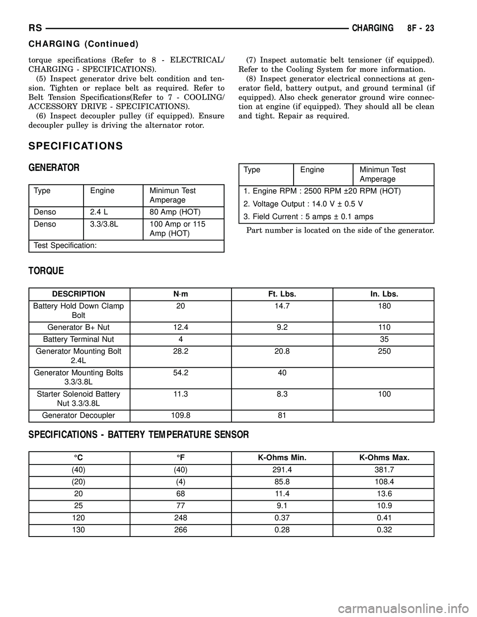
SPECIFICATIONS
GENERATOR
Type Engine Minimun Test
Amperage
Denso 2.4 L 80 Amp (HOT)
Denso 3.3/3.8L 100 Amp or 115
Amp (HOT)
Test Specification:
Type Engine Minimun Test
Amperage
1. Engine RPM : 2500 RPM 20 RPM (HOT)
2. Voltage Output : 14.0 V 0.5 V
3. Field Current : 5 amps 0.1 amps
Part number is located on the side of the generator.
TORQUE
DESCRIPTION N´m Ft. Lbs. In. Lbs.
Battery Hold Down Clamp
Bolt20 14.7 180
Generator B+ Nut 12.4 9.2 110
Battery Terminal Nut 4 35
Generator Mounting Bolt
2.4L28.2 20.8 250
Generator Mounting Bolts
3.3/3.8L54.2 40
Starter Solenoid Battery
Nut 3.3/3.8L11.3 8.3 100
Generator Decoupler 109.8 81
SPECIFICATIONS - BATTERY TEMPERATURE SENSOR
ÉC ÉF K-Ohms Min. K-Ohms Max.
(40) (40) 291.4 381.7
(20) (4) 85.8 108.4
20 68 11.4 13.6
25 77 9.1 10.9
120 248 0.37 0.41
130 266 0.28 0.32
RSCHARGING8F-23
CHARGING (Continued)
Page 337 of 2339
the battery, if required. Refer to the Battery section
for more information.
²Ignition Switch- Visually inspect the ignition
switch for indications of physical damage and loose
or corroded wire harness connections.
²Transmission Range Sensor or Park/Neu-
tral Switch- Visually inspect the transmission
range sensor for indications of physical damage and
loose or corroded wire harness connections.
²Starter Relay- Visually inspect the starter
relay for indications of physical damage and loose or
corroded wire harness connections.
²Starter Motor- Visually inspect the starter
motor for indications of physical damage and loose or
corroded wire harness connections.²Starter Solenoid- Visually inspect the starter
solenoid for indications of physical damage and loose
or corroded wire harness connections.
²Wiring- Visually inspect the wire harness for
damage. Repair or replace any faulty wiring, as
required. Check for loose or corroded wire harness
connections at main engine ground and remote jump
post.
²Power Distribution Center (PDC)- Visually
inspect the B+ connections at the PDC for physical
damage and loose or corroded harness connections.
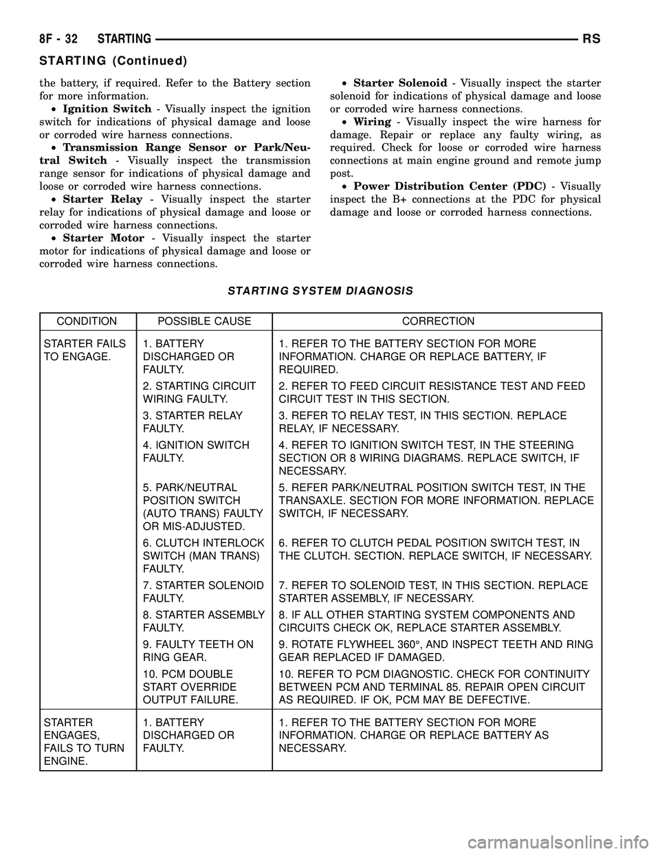
STARTING SYSTEM DIAGNOSIS
CONDITION POSSIBLE CAUSE CORRECTION
STARTER FAILS
TO ENGAGE.1. BATTERY
DISCHARGED OR
FAULTY.1. REFER TO THE BATTERY SECTION FOR MORE
INFORMATION. CHARGE OR REPLACE BATTERY, IF
REQUIRED.
2. STARTING CIRCUIT
WIRING FAULTY.2. REFER TO FEED CIRCUIT RESISTANCE TEST AND FEED
CIRCUIT TEST IN THIS SECTION.
3. STARTER RELAY
FAULTY.3. REFER TO RELAY TEST, IN THIS SECTION. REPLACE
RELAY, IF NECESSARY.
4. IGNITION SWITCH
FAULTY.4. REFER TO IGNITION SWITCH TEST, IN THE STEERING
SECTION OR 8 WIRING DIAGRAMS. REPLACE SWITCH, IF
NECESSARY.
5. PARK/NEUTRAL
POSITION SWITCH
(AUTO TRANS) FAULTY
OR MIS-ADJUSTED.5. REFER PARK/NEUTRAL POSITION SWITCH TEST, IN THE
TRANSAXLE. SECTION FOR MORE INFORMATION. REPLACE
SWITCH, IF NECESSARY.
6. CLUTCH INTERLOCK
SWITCH (MAN TRANS)
FAULTY.6. REFER TO CLUTCH PEDAL POSITION SWITCH TEST, IN
THE CLUTCH. SECTION. REPLACE SWITCH, IF NECESSARY.
7. STARTER SOLENOID
FAULTY.7. REFER TO SOLENOID TEST, IN THIS SECTION. REPLACE
STARTER ASSEMBLY, IF NECESSARY.
8. STARTER ASSEMBLY
FAULTY.8. IF ALL OTHER STARTING SYSTEM COMPONENTS AND
CIRCUITS CHECK OK, REPLACE STARTER ASSEMBLY.
9. FAULTY TEETH ON
RING GEAR.9. ROTATE FLYWHEEL 360É, AND INSPECT TEETH AND RING
GEAR REPLACED IF DAMAGED.
10. PCM DOUBLE
START OVERRIDE
OUTPUT FAILURE.10. REFER TO PCM DIAGNOSTIC. CHECK FOR CONTINUITY
BETWEEN PCM AND TERMINAL 85. REPAIR OPEN CIRCUIT
AS REQUIRED. IF OK, PCM MAY BE DEFECTIVE.
STARTER
ENGAGES,
FAILS TO TURN
ENGINE.1. BATTERY
DISCHARGED OR
FAULTY.1. REFER TO THE BATTERY SECTION FOR MORE
INFORMATION. CHARGE OR REPLACE BATTERY AS
NECESSARY.
8F - 32 STARTINGRS
STARTING (Continued)
Page 338 of 2339
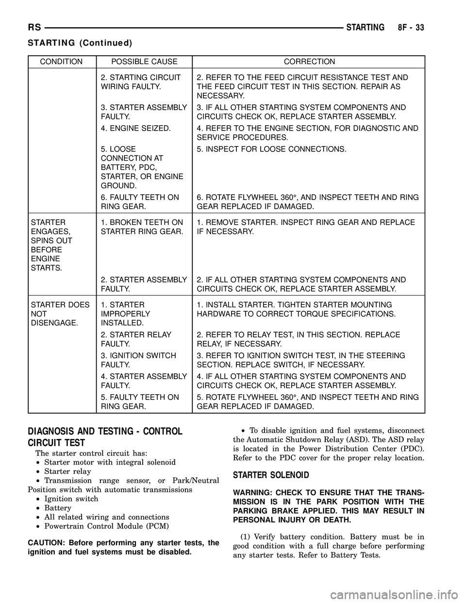
CONDITION POSSIBLE CAUSE CORRECTION
2. STARTING CIRCUIT
WIRING FAULTY.2. REFER TO THE FEED CIRCUIT RESISTANCE TEST AND
THE FEED CIRCUIT TEST IN THIS SECTION. REPAIR AS
NECESSARY.
3. STARTER ASSEMBLY
FAULTY.3. IF ALL OTHER STARTING SYSTEM COMPONENTS AND
CIRCUITS CHECK OK, REPLACE STARTER ASSEMBLY.
4. ENGINE SEIZED. 4. REFER TO THE ENGINE SECTION, FOR DIAGNOSTIC AND
SERVICE PROCEDURES.
5. LOOSE
CONNECTION AT
BATTERY, PDC,
STARTER, OR ENGINE
GROUND.5. INSPECT FOR LOOSE CONNECTIONS.
6. FAULTY TEETH ON
RING GEAR.6. ROTATE FLYWHEEL 360É, AND INSPECT TEETH AND RING
GEAR REPLACED IF DAMAGED.
STARTER
ENGAGES,
SPINS OUT
BEFORE
ENGINE
STARTS.1. BROKEN TEETH ON
STARTER RING GEAR.1. REMOVE STARTER. INSPECT RING GEAR AND REPLACE
IF NECESSARY.
2. STARTER ASSEMBLY
FAULTY.2. IF ALL OTHER STARTING SYSTEM COMPONENTS AND
CIRCUITS CHECK OK, REPLACE STARTER ASSEMBLY.
STARTER DOES
NOT
DISENGAGE.1. STARTER
IMPROPERLY
INSTALLED.1. INSTALL STARTER. TIGHTEN STARTER MOUNTING
HARDWARE TO CORRECT TORQUE SPECIFICATIONS.
2. STARTER RELAY
FAULTY.2. REFER TO RELAY TEST, IN THIS SECTION. REPLACE
RELAY, IF NECESSARY.
3. IGNITION SWITCH
FAULTY.3. REFER TO IGNITION SWITCH TEST, IN THE STEERING
SECTION. REPLACE SWITCH, IF NECESSARY.
4. STARTER ASSEMBLY
FAULTY.4. IF ALL OTHER STARTING SYSTEM COMPONENTS AND
CIRCUITS CHECK OK, REPLACE STARTER ASSEMBLY.
5. FAULTY TEETH ON
RING GEAR.5. ROTATE FLYWHEEL 360É, AND INSPECT TEETH AND RING
GEAR REPLACED IF DAMAGED.
DIAGNOSIS AND TESTING - CONTROL
CIRCUIT TEST
The starter control circuit has:
²Starter motor with integral solenoid
²Starter relay
²Transmission range sensor, or Park/Neutral
Position switch with automatic transmissions
²Ignition switch
²Battery
²All related wiring and connections
²Powertrain Control Module (PCM)
CAUTION: Before performing any starter tests, the
ignition and fuel systems must be disabled.²To disable ignition and fuel systems, disconnect
the Automatic Shutdown Relay (ASD). The ASD relay
is located in the Power Distribution Center (PDC).
Refer to the PDC cover for the proper relay location.
STARTER SOLENOID
WARNING: CHECK TO ENSURE THAT THE TRANS-
MISSION IS IN THE PARK POSITION WITH THE
PARKING BRAKE APPLIED. THIS MAY RESULT IN
PERSONAL INJURY OR DEATH.
(1) Verify battery condition. Battery must be in
good condition with a full charge before performing
any starter tests. Refer to Battery Tests.
RSSTARTING8F-33
STARTING (Continued)
Page 339 of 2339
(2) Perform Starter Solenoid test BEFORE per-
forming the starter relay test.
(3) Perform a visual inspection of the starter/
starter solenoid for corrosion, loose connections or
faulty wiring.
(4) Locate and remove the starter relay from the
Power Distribution Center (PDC). Refer to the PDC
label for relay identification and location.
(5) Connect a remote starter switch or a jumper
wire between the remote battery positive post and
terminal 87 of the starter relay connector.
(a) If engine cranks, starter/starter solenoid is
good. Go to the Starter Relay Test.
(b) If engine does not crank or solenoid chatters,
check wiring and connectors from starter relay to
starter solenoid and from the battery positive ter-
minal to starter post for loose or corroded connec-
tions. Particularly at starter terminals.
(c) Repeat test. If engine still fails to crank prop-
erly, trouble is within starter or starter mounted
solenoid, and replace starter. Inspect the ring gear
teeth.
STARTER RELAY
WARNING: CHECK TO ENSURE THAT THE TRANS-
MISSION IS IN THE PARK/NEUTRAL POSITION
WITH THE PARKING BRAKE APPLIED. THIS MAY
RESULT IN PERSONAL INJURY OR DEATH.
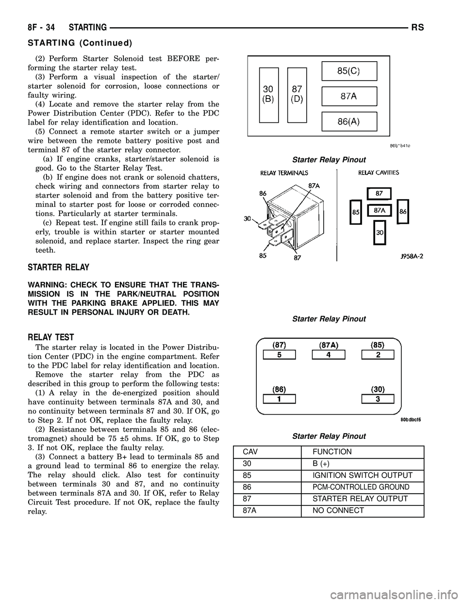
RELAY TEST
The starter relay is located in the Power Distribu-
tion Center (PDC) in the engine compartment. Refer
to the PDC label for relay identification and location.
Remove the starter relay from the PDC as
described in this group to perform the following tests:
(1) A relay in the de-energized position should
have continuity between terminals 87A and 30, and
no continuity between terminals 87 and 30. If OK, go
to Step 2. If not OK, replace the faulty relay.
(2) Resistance between terminals 85 and 86 (elec-
tromagnet) should be 75 5 ohms. If OK, go to Step
3. If not OK, replace the faulty relay.
(3) Connect a battery B+ lead to terminals 85 and
a ground lead to terminal 86 to energize the relay.
The relay should click. Also test for continuity
between terminals 30 and 87, and no continuity
between terminals 87A and 30. If OK, refer to Relay
Circuit Test procedure. If not OK, replace the faulty
relay.
CAV FUNCTION
30 B (+)
85 IGNITION SWITCH OUTPUT
86
PCM-CONTROLLED GROUND
87 STARTER RELAY OUTPUT
87A NO CONNECT
Starter Relay Pinout
Starter Relay Pinout
Starter Relay Pinout
8F - 34 STARTINGRS
STARTING (Continued)
Page 340 of 2339
RELAY CIRCUIT TEST
(1) The relay common feed terminal cavity (30) is
connected to battery voltage and should be hot at all
times. If OK, go to Step 2. If not OK, repair the open
circuit to the PDC fuse as required.
(2) The relay normally closed terminal (87A) is
connected to terminal 30 in the de-energized position,
but is not used for this application. Go to Step 3.
(3) The relay normally open terminal (87) is con-
nected to the common feed terminal (30) in the ener-
gized position. This terminal supplies battery voltage
to the starter solenoid field coils. There should be
continuity between the cavity for relay terminal 87
and the starter solenoid terminal at all times. If OK,
go to Step 4. If not OK, repair the open circuit to the
starter solenoid as required.
(4) The coil battery terminal (85) is connected to
the electromagnet in the relay. It is energized when
the ignition switch is held in the Start position and
the clutch pedal is depressed (manual trans). Check
for battery voltage at the cavity for relay terminal 86
with the ignition switch in the Start position and the
clutch pedal is depressed (manual trans), and no
voltage when the ignition switch is released to the
On position. If OK, go to Step 5. If not OK, check for
an open or short circuit to the ignition switch and
repair, if required. If the circuit to the ignition switch
is OK, see the Ignition Switch Test procedure in this
group.
(5) The coil ground terminal (86) is connected to
the electromagnet in the relay. It is grounded by the
PCM if the conditions are right to start the car. For
automatic trans. cars the PCM must see Park Neu-
tral switch low and near zero engine speed (rpm).
For manual trans. cars the PCM only needs to see
near zero engine speed (rpm) and low clutch inter-
lock input and see near zero engine speed (rpm). To
diagnose the Park Neutral switch of the trans range
sensor refer to the transaxle section. Check for conti-
nuity to ground while the ignition switch is in the
start position and if equipped the clutch pedal
depressed. If not OK and the vehicle has an auto-
matic trans. verify Park Neutral switch operation. If
that checks OK check for continuity between PCM
and the terminal 86. Repair open circuit as required.
Also check the clutch interlock switch operation if
equipped with a manual transmission. If OK, the
PCM may be defective.
SAFETY SWITCHES
For diagnostics of the Transmission Range Sensor,
refer to the Transaxle section for more information.
If equipped with Clutch Interlock/Upstop Switch,
refer to Diagnosis and Testing in the Clutch section.
IGNITION SWITCH
After testing starter solenoid and relay, test igni-
tion switch and wiring. Refer to the Ignition Section
or Wiring Diagrams for more information. Check all
wiring for opens or shorts, and all connectors for
being loose or corroded.
BATTERY
For battery diagnosis and testing, refer to the Bat-
tery section for procedures.
ALL RELATED WIRING AND CONNECTORS
Refer to Wiring Diagrams for more information.
DIAGNOSIS AND TESTING - FEED CIRCUIT
RESISTANCE TEST
Before proceeding with this operation, review Diag-
nostic Preparation and Starter Feed Circuit Tests.
The following operation will require a voltmeter,
accurate to 1/10 of a volt.
CAUTION: Ignition and Fuel systems must be dis-
abled to prevent engine start while performing the
following tests.
(1) To disable the Ignition and Fuel systems, dis-
connect the Automatic Shutdown Relay (ASD). The
ASD relay is located in the Power Distribution Cen-
ter (PDC). Refer to the PDC cover for proper relay
location.
(2) Gain access to battery terminals.
(3) With all wiring harnesses and components
properly connected, perform the following:
(a) Connect the negative lead of the voltmeter to
the battery negative post, and positive lead to the
battery negative cable clamp. Rotate and hold the
ignition switch in the START position. Observe the
voltmeter. If voltage is detected, correct poor con-
tact between cable clamp and post.
(b) Connect positive lead of the voltmeter to the
battery positive post, and negative lead to the bat-
tery positive cable clamp. Rotate and hold the igni-
tion switch key in the START position. Observe the
voltmeter. If voltage is detected, correct poor con-
tact between the cable clamp and post.
(c) Connect negative lead of voltmeter to battery
negative terminal, and positive lead to engine
block near the battery cable attaching point.
Rotate and hold the ignition switch in the START
position. If voltage reads above 0.2 volt, correct
poor contact at ground cable attaching point. If
voltage reading is still above 0.2 volt after correct-
ing poor contacts, replace ground cable.
(4) Connect positive voltmeter lead to the starter
motor housing and the negative lead to the battery
negative terminal. Hold the ignition switch key in
RSSTARTING8F-35
STARTING (Continued)
Page 341 of 2339
the START position. If voltage reads above 0.2 volt,
correct poor starter to engine ground.
(a) Connect the positive voltmeter lead to the
battery positive terminal, and negative lead to bat-
tery cable terminal on starter solenoid. Rotate and
hold the ignition switch in the START position. If
voltage reads above 0.2 volt, correct poor contact at
battery cable to solenoid connection. If reading is
still above 0.2 volt after correcting poor contacts,
replace battery positive cable.
(b) If resistance tests do not detect feed circuit
failures, replace the starter motor.
DIAGNOSIS AND TESTING - FEED CIRCUIT
TEST
NOTE: The following results are based upon the
vehicle being at room temperature.
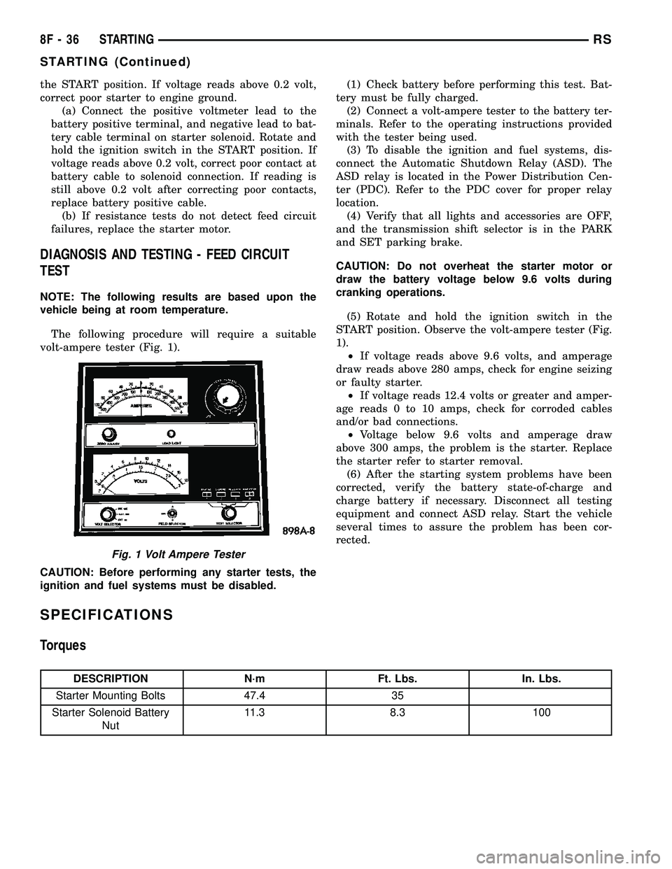
The following procedure will require a suitable
volt-ampere tester (Fig. 1).
CAUTION: Before performing any starter tests, the
ignition and fuel systems must be disabled.(1) Check battery before performing this test. Bat-
tery must be fully charged.
(2) Connect a volt-ampere tester to the battery ter-
minals. Refer to the operating instructions provided
with the tester being used.
(3) To disable the ignition and fuel systems, dis-
connect the Automatic Shutdown Relay (ASD). The
ASD relay is located in the Power Distribution Cen-
ter (PDC). Refer to the PDC cover for proper relay
location.
(4) Verify that all lights and accessories are OFF,
and the transmission shift selector is in the PARK
and SET parking brake.
CAUTION: Do not overheat the starter motor or
draw the battery voltage below 9.6 volts during
cranking operations.
(5) Rotate and hold the ignition switch in the
START position. Observe the volt-ampere tester (Fig.
1).
²If voltage reads above 9.6 volts, and amperage
draw reads above 280 amps, check for engine seizing
or faulty starter.
²If voltage reads 12.4 volts or greater and amper-
age reads 0 to 10 amps, check for corroded cables
and/or bad connections.
²Voltage below 9.6 volts and amperage draw
above 300 amps, the problem is the starter. Replace
the starter refer to starter removal.
(6) After the starting system problems have been
corrected, verify the battery state-of-charge and
charge battery if necessary. Disconnect all testing
equipment and connect ASD relay. Start the vehicle
several times to assure the problem has been cor-
rected.
SPECIFICATIONS
Torques
DESCRIPTION N´m Ft. Lbs. In. Lbs.
Starter Mounting Bolts 47.4 35
Starter Solenoid Battery
Nut11.3 8.3 100
Fig. 1 Volt Ampere Tester
8F - 36 STARTINGRS
STARTING (Continued)
Page 360 of 2339
HORN
TABLE OF CONTENTS
page page
HORN SYSTEM
DESCRIPTION..........................1
OPERATION............................1
DIAGNOSIS AND TESTING
HORN SYSTEM........................1
HORN
DIAGNOSIS AND TESTING
HORN...............................3REMOVAL.............................4
INSTALLATION..........................4
HORN SWITCH
DESCRIPTION..........................4
HORN SYSTEM
DESCRIPTION
WARNING: ON VEHICLES EQUIPPED WITH AIR-
BAG, REFER TO ELECTRICAL, RESTRAINTS FOR
SAFETY PRECAUTIONS. DISCONNECT THE NEGA-
TIVE CABLE FROM THE BATTERY BEFORE SER-
VICING COMPONENTS INVOLVING THE AIRBAG
SYSTEM. ACCIDENTAL DEPLOYMENT OF AIRBAG
AND PERSONAL INJURY CAN RESULT.
The horn circuit consists of a horn switch, clock-
spring, horn relay, horns and Integrated Power Mod-
ule (IPM). The horn switch is a membrane switch
located in the airbag trim cover. The horns are
located forward of the left front wheel behind the
bumper fascia.
OPERATION
The horn relay plugs into the Integrated Power
Module (IPM) which is located in the engine com-
partment. For circuit information and component
locations, refer to the appropriate wiring information.
The wiring information includes wiring diagrams,
proper wire and connector repair procedures, details
of wire harness routing and retention, connector pin-
out information and location views for the various
wire harness connectors, splices and grounds.
The horns will not function if the switch is
ªCLOSEDº for more than 30 seconds. Once the
switch is ªOPENº, a 20±30 second delay will occur
before the horns are functional again.
DIAGNOSIS AND TESTING
HORN SYSTEM
WARNING: ON VEHICLES EQUIPPED WITH AIR-
BAGS, REFER TO ELECTRICAL, RESTRAINTS
BEFORE ATTEMPTING ANY STEERING WHEEL,
STEERING COLUMN, OR INSTRUMENT PANEL
COMPONENT DIAGNOSIS OR SERVICE. FAILURE
TO TAKE THE PROPER PRECAUTIONS COULD
RESULT IN ACCIDENTAL AIRBAG DEPLOYMENT
AND POSSIBLE PERSONAL INJURY.
Refer to Horn System Test below. If the horn does
not sound, check horn fuse located in the Integrated
Power Module (IPM). If the fuse is blown, replace
with the correct fuse. If the horns fail to sound and
the new fuse blows when depressing the horn switch,
a short circuit in the horn or the horn wiring
between the fuse terminal and the horn is responsi-
ble, or a defective horn switch allowed the horn to
burn out is responsible.
If the fuse is OK, test horn relay.
If the relay is OK, test horn.
CAUTION: Continuous sounding of horn may
cause horn failure.
Should the horn sound continuously, unplug the
horn relay from IPM.
Refer to the appropriate wiring information.
RSHORN8H-1
Page 366 of 2339

FIRING ORDERAUTO SHUT DOWN RELAY
DESCRIPTION
The relay is located in the Power Distribution Cen-
ter (PDC). For the location of the relay within the
PDC, refer to the PDC cover for location. Check elec-
trical terminals for corrosion and repair as necessary
OPERATION
The engine switched battery (NGC vehicles)
informs the PCM when the ASD relay energizes. A 12
volt signal at this input indicates to the PCM that
the ASD has been activated. This input is also used
to power certain drivers on NGC vehicles.
When energized, the ASD relay on NGC vehicles
provides power to operate the injectors, ignition coil,
generator field, O2 sensor heaters (both upstream
and downstream), evaporative purge solenoid, EGR
solenoid (if equipped) wastegate solenoid (if
equipped), and NVLD solenoid (if equipped).
The ASD relay also provides a sense circuit to the
PCM for diagnostic purposes. If the PCM does not
receive 12 volts from this input after grounding the
control side of the ASD relay, it sets a Diagnostic
Trouble Code (DTC). The PCM energizes the ASD
any time there is an engine speed that exceeds a pre-
determined value (typically about 50 rpm). The ASD
relay can also be energized after the engine has been
turned off to perform an O2 sensor heater test, if
vehicle is equipped with OBD II diagnostics.
As mentioned earlier, the PCM energizes the ASD
relay during an O2 sensor heater test. On NGC vehi-
cles it checks the O2 heater upon vehicle start. The
PCM still operates internally to perform several
checks, including monitoring the O2 sensor heaters.
FIRING ORDER 2.4L
Firing Order 1-2-3-4-5-6 3.3/3.8L
1 - Electrical Connector
RSIGNITION CONTROL8I-3
IGNITION CONTROL (Continued)
Page 372 of 2339
(4) Lower vehicle.
(5) Connect the negative cable.
SPARK PLUG
DESCRIPTION
DESCRIPTION - STANDARD 4 CYLINDER
All engines use resistor spark plugs. They have
resistance values ranging from 6,000 to 20,000 ohms
when checked with at least a 1000 volt spark plug
tester.
Do not use an ohm meter to check the resis-
tance of the spark plugs. This will give an inac-
curate reading.
Refer to the Specifications section for gap and type
of spark plug.
DESCRIPTION - PLATINUM PLUGS
The V6 engines use platinum resistor spark plugs.
They have resistance values of 6,000 to 20,000 ohms
when checked with at least a 1000 volt tester. For
spark plug identification and specifications, Refer to
the Specifications section.
Do not use an ohm meter to check the resis-
tance of the spark plugs. This will give an inac-
curate reading.When the spark plugs use a single or double plat-
inum tips and they have a recommended service life
of 100,000 miles for normal driving conditions per
schedule A in this manual. The spark plugs have a
recommended service life of 75,000 miles for severe
driving conditions per schedule B in this manual. A
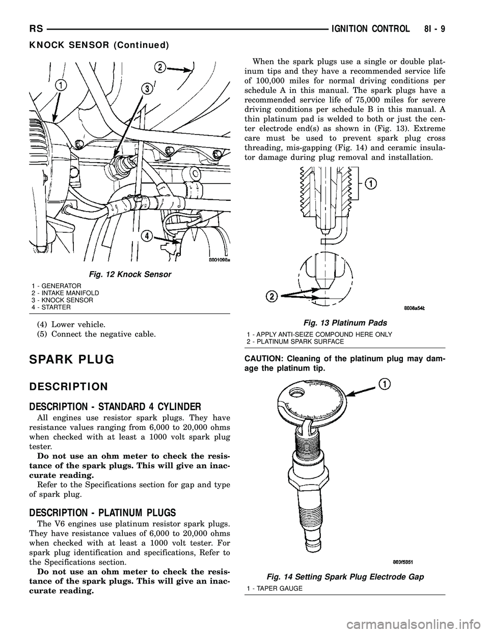
thin platinum pad is welded to both or just the cen-
ter electrode end(s) as shown in (Fig. 13). Extreme
care must be used to prevent spark plug cross
threading, mis-gapping (Fig. 14) and ceramic insula-
tor damage during plug removal and installation.
CAUTION: Cleaning of the platinum plug may dam-
age the platinum tip.
Fig. 12 Knock Sensor
1 - GENERATOR
2 - INTAKE MANIFOLD
3 - KNOCK SENSOR
4-STARTER
Fig. 13 Platinum Pads
1 - APPLY ANTI-SEIZE COMPOUND HERE ONLY
2 - PLATINUM SPARK SURFACE
Fig. 14 Setting Spark Plug Electrode Gap
1 - TAPER GAUGE
RSIGNITION CONTROL8I-9
KNOCK SENSOR (Continued)
Page 375 of 2339
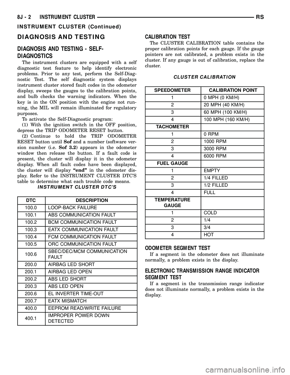
DIAGNOSIS AND TESTING
DIAGNOSIS AND TESTING - SELF-
DIAGNOSTICS
The instrument clusters are equipped with a self
diagnostic test feature to help identify electronic
problems. Prior to any test, perform the Self-Diag-
nostic Test. The self diagnostic system displays
instrument cluster stored fault codes in the odometer
display, sweeps the gauges to the calibration points,
and bulb checks the warning indicators. When the
key is in the ON position with the engine not run-
ning, the MIL will remain illuminated for regulatory
purposes.
To activate the Self-Diagnostic program:
(1) With the ignition switch in the OFF position,
depress the TRIP ODOMETER RESET button.
(2) Continue to hold the TRIP ODOMETER
RESET button untilSofand a number (software ver-
sion number (i.e.Sof 3.2) appears in the odometer
window then release the button. If a fault code is
present, the cluster will display it in the odometer
display. When all fault codes have been displayed,
the cluster will displayªendºin the odometer dis-
play. Refer to the INSTRUMENT CLUSTER DTC'S
table to determine what each trouble code means.
INSTRUMENT CLUSTER DTC'S
DTC DESCRIPTION
100.0 LOOP-BACK FAILURE
100.1 ABS COMMUNICATION FAULT
100.2 BCM COMMUNICATION FAULT
100.3 EATX COMMUNICATION FAULT
100.4 FCM COMMUNICATION FAULT
100.5 ORC COMMUNICATION FAULT
100.6SBEC/DEC/MCM COMMUNICATION
FAULT
200.0 AIRBAG LED SHORT
200.1 AIRBAG LED OPEN
200.2 ABS LED SHORT
200.3 ABS LED OPEN
200.6 EL INVERTER TIME-OUT
200.7 EATX MISMATCH
400.0 EEPROM READ/WRITE FAILURE
400.1IMPROPER POWER DOWN
DETECTED
CALIBRATION TEST
The CLUSTER CALIBRATION table contains the
proper calibration points for each gauge. If the gauge
pointers are not calibrated, a problem exists in the
cluster. If any gauge is out of calibration, replace the
cluster.
CLUSTER CALIBRATION
SPEEDOMETER CALIBRATION POINT
1 0 MPH (0 KM/H)
2 20 MPH (40 KM/H)
3 60 MPH (100 KM/H)
4 100 MPH (160 KM/H)
TACHOMETER
1 0 RPM
2 1000 RPM
3 3000 RPM
4 6000 RPM
FUEL GAUGE
1 EMPTY
2 1/4 FILLED
3 1/2 FILLED
4 FULL
TEMPERATURE
GAUGE
1 COLD
2 1/4
3 3/4
4 HOT
ODOMETER SEGMENT TEST
If a segment in the odometer does not illuminate
normally, a problem exists in the display.
ELECTRONIC TRANSMISSION RANGE INDICATOR
SEGMENT TEST
If a segment in the transmission range indicator
does not illuminate normally, a problem exists in the
display.
8J - 2 INSTRUMENT CLUSTERRS
INSTRUMENT CLUSTER (Continued)