hood open CHRYSLER VOYAGER 2005 Workshop Manual
[x] Cancel search | Manufacturer: CHRYSLER, Model Year: 2005, Model line: VOYAGER, Model: CHRYSLER VOYAGER 2005Pages: 2339, PDF Size: 59.69 MB
Page 2227 of 2339
REMOVAL
2.4L/3.3L/3.8L ENGINES
WARNING: REFER TO THE APPLICABLE WARN-
INGS AND CAUTIONS FOR THIS SYSTEM BEFORE
PERFORMING THE FOLLOWING OPERATION (Refer
to 24 - HEATING & AIR CONDITIONING/PLUMBING -
FRONT - WARNING - A/C PLUMBING) and (Refer to
24 - HEATING & AIR CONDITIONING/PLUMBING -
FRONT - CAUTION - A/C PLUMBING).
NOTE: Before removing the A/C condenser, note the
location of each of the radiator and condenser air
seals. These air seals are used to direct air through
the A/C condenser and radiator. The air seals must
be reinstalled in their proper locations in order for
the A/C and engine cooling systems to perform as
designed.
(1) Recover the refrigerant from the refrigerant
system (Refer to 24 - HEATING & AIR CONDITION-
ING/PLUMBING - FRONT/REFRIGERANT - STAN-
DARD PROCEDURE - REFRIGERANT SYSTEM
RECOVERY).
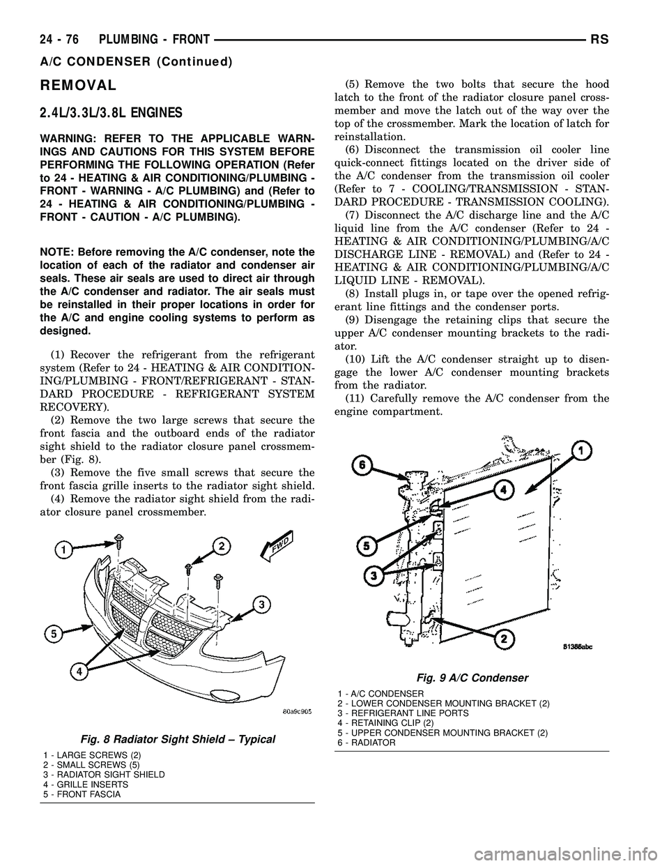
(2) Remove the two large screws that secure the
front fascia and the outboard ends of the radiator
sight shield to the radiator closure panel crossmem-
ber (Fig. 8).
(3) Remove the five small screws that secure the
front fascia grille inserts to the radiator sight shield.
(4) Remove the radiator sight shield from the radi-
ator closure panel crossmember.(5) Remove the two bolts that secure the hood
latch to the front of the radiator closure panel cross-
member and move the latch out of the way over the
top of the crossmember. Mark the location of latch for
reinstallation.
(6) Disconnect the transmission oil cooler line
quick-connect fittings located on the driver side of
the A/C condenser from the transmission oil cooler
(Refer to 7 - COOLING/TRANSMISSION - STAN-
DARD PROCEDURE - TRANSMISSION COOLING).
(7) Disconnect the A/C discharge line and the A/C
liquid line from the A/C condenser (Refer to 24 -
HEATING & AIR CONDITIONING/PLUMBING/A/C
DISCHARGE LINE - REMOVAL) and (Refer to 24 -
HEATING & AIR CONDITIONING/PLUMBING/A/C
LIQUID LINE - REMOVAL).
(8) Install plugs in, or tape over the opened refrig-
erant line fittings and the condenser ports.
(9) Disengage the retaining clips that secure the
upper A/C condenser mounting brackets to the radi-
ator.
(10) Lift the A/C condenser straight up to disen-
gage the lower A/C condenser mounting brackets
from the radiator.
(11) Carefully remove the A/C condenser from the
engine compartment.
Fig. 8 Radiator Sight Shield ± Typical
1 - LARGE SCREWS (2)
2 - SMALL SCREWS (5)
3 - RADIATOR SIGHT SHIELD
4 - GRILLE INSERTS
5 - FRONT FASCIA
Fig. 9 A/C Condenser
1 - A/C CONDENSER
2 - LOWER CONDENSER MOUNTING BRACKET (2)
3 - REFRIGERANT LINE PORTS
4 - RETAINING CLIP (2)
5 - UPPER CONDENSER MOUNTING BRACKET (2)
6 - RADIATOR
24 - 76 PLUMBING - FRONTRS
A/C CONDENSER (Continued)
Page 2228 of 2339
2.5L/2.8L DIESEL ENGINES
WARNING: REFER TO THE APPLICABLE WARN-
INGS AND CAUTIONS FOR THIS SYSTEM BEFORE
PERFORMING THE FOLLOWING OPERATION (Refer
to 24 - HEATING & AIR CONDITIONING/PLUMBING -
FRONT - WARNING - A/C PLUMBING) and (Refer to
24 - HEATING & AIR CONDITIONING/PLUMBING -
FRONT - CAUTION - A/C PLUMBING).
NOTE: Before removing the A/C condenser, note the
location of each of the radiator and condenser air
seals. These air seals are used to direct air through
the A/C condenser and radiator. The air seals must
be reinstalled in their proper locations in order for
the A/C and engine cooling systems to perform as
designed.
(1) Recover the refrigerant from the refrigerant
system (Refer to 24 - HEATING & AIR CONDITION-
ING/PLUMBING - FRONT/REFRIGERANT - STAN-
DARD PROCEDURE - REFRIGERANT SYSTEM
RECOVERY).
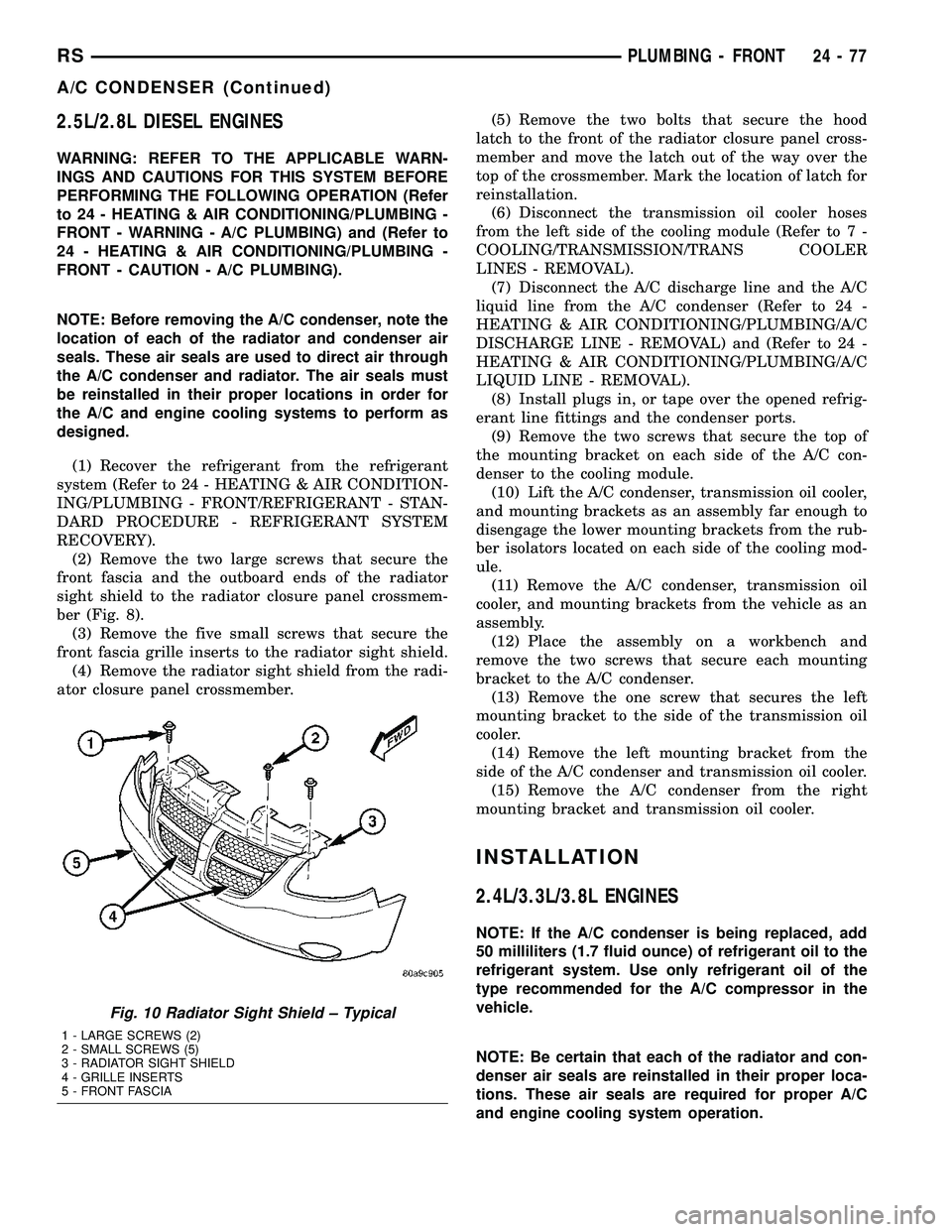
(2) Remove the two large screws that secure the
front fascia and the outboard ends of the radiator
sight shield to the radiator closure panel crossmem-
ber (Fig. 8).
(3) Remove the five small screws that secure the
front fascia grille inserts to the radiator sight shield.
(4) Remove the radiator sight shield from the radi-
ator closure panel crossmember.(5) Remove the two bolts that secure the hood
latch to the front of the radiator closure panel cross-
member and move the latch out of the way over the
top of the crossmember. Mark the location of latch for
reinstallation.
(6) Disconnect the transmission oil cooler hoses
from the left side of the cooling module (Refer to 7 -
COOLING/TRANSMISSION/TRANS COOLER
LINES - REMOVAL).
(7) Disconnect the A/C discharge line and the A/C
liquid line from the A/C condenser (Refer to 24 -
HEATING & AIR CONDITIONING/PLUMBING/A/C
DISCHARGE LINE - REMOVAL) and (Refer to 24 -
HEATING & AIR CONDITIONING/PLUMBING/A/C
LIQUID LINE - REMOVAL).
(8) Install plugs in, or tape over the opened refrig-
erant line fittings and the condenser ports.
(9) Remove the two screws that secure the top of
the mounting bracket on each side of the A/C con-
denser to the cooling module.
(10) Lift the A/C condenser, transmission oil cooler,
and mounting brackets as an assembly far enough to
disengage the lower mounting brackets from the rub-
ber isolators located on each side of the cooling mod-
ule.
(11) Remove the A/C condenser, transmission oil
cooler, and mounting brackets from the vehicle as an
assembly.
(12) Place the assembly on a workbench and
remove the two screws that secure each mounting
bracket to the A/C condenser.
(13) Remove the one screw that secures the left
mounting bracket to the side of the transmission oil
cooler.
(14) Remove the left mounting bracket from the
side of the A/C condenser and transmission oil cooler.
(15) Remove the A/C condenser from the right
mounting bracket and transmission oil cooler.
INSTALLATION
2.4L/3.3L/3.8L ENGINES
NOTE: If the A/C condenser is being replaced, add
50 milliliters (1.7 fluid ounce) of refrigerant oil to the
refrigerant system. Use only refrigerant oil of the
type recommended for the A/C compressor in the
vehicle.
NOTE: Be certain that each of the radiator and con-
denser air seals are reinstalled in their proper loca-
tions. These air seals are required for proper A/C
and engine cooling system operation.
Fig. 10 Radiator Sight Shield ± Typical
1 - LARGE SCREWS (2)
2 - SMALL SCREWS (5)
3 - RADIATOR SIGHT SHIELD
4 - GRILLE INSERTS
5 - FRONT FASCIA
RSPLUMBING - FRONT24-77
A/C CONDENSER (Continued)
Page 2229 of 2339
(1) Position the A/C condenser into the engine
compartment.
(2) Carefully lower the A/C condenser straight
down to engage the lower mounting brackets to the
radiator.
(3) Engage the upper A/C condenser mounting
brackets to the radiator. Be sure that the upper
retaining clips are fully engaged to the upper mount-
ing brackets.
(4) Remove the tape or plugs from the opened
refrigerant line fittings and the condenser ports.
(5) Connect the A/C discharge line and the A/C liq-
uid line to the A/C condenser (Refer to 24 - HEAT-
ING & AIR CONDITIONING/PLUMBING/A/C
DISCHARGE LINE - INSTALLATION) and (Refer to
24 - HEATING & AIR CONDITIONING/PLUMBING/
A/C LIQUID LINE - INSTALLATION).
(6) Connect the transmission oil cooler lines to the
A/C Condenser. Be sure that the quick-connect fit-
tings are fully engaged to the cooler tapping block
(Refer to 7 - COOLING/TRANSMISSION - STAN-
DARD PROCEDURE - TRANSMISSION COOLING).
(7) Position the hood latch onto the front of the
radiator closure panel crossmember.
(8) Install the two screws that secure the hood
latch to the crossmember. Check and adjust the hoodlatch as required. Tighten the bolts to 14 N´m (123
in. lbs.).
(9) Position the radiator sight shield onto the radi-
ator closure panel crossmember.
(10) Install the five small screws that secure the
front fascia grille inserts to the radiator sight shield.
Tighten the screws to 2 N´m (17 in. lbs.).
(11) Install the two large screws that secure the
front fascia and the outboard ends of the radiator
sight shield to the radiator closure panel crossmem-
ber. Tighten the screws to 6 N´m (53 in. lbs.).
(12) Evacuate the refrigerant system (Refer to 24 -
HEATING & AIR CONDITIONING/PLUMBING -
FRONT/REFRIGERANT - STANDARD PROCE-
DURE - REFRIGERANT SYSTEM EVACUATE).
(13) Charge the refrigerant system (Refer to 24 -
HEATING & AIR CONDITIONING/PLUMBING -
FRONT/REFRIGERANT - STANDARD PROCE-
DURE - REFRIGERANT SYSTEM CHARGE).
2.5L/2.8L DIESEL ENGINES
NOTE: If the A/C condenser is being replaced, add
50 milliliters (1.7 fluid ounce) of refrigerant oil to the
refrigerant system. Use only refrigerant oil of the
type recommended for the A/C compressor in the
vehicle.
NOTE: Be certain that each of the radiator and con-
denser air seals are reinstalled in their proper loca-
tions. These air seals are required for proper A/C
and engine cooling system operation.
(1) Position the A/C condenser onto the right
mounting bracket and transmission oil cooler unit.
(2) Position the left mounting bracket onto the side
of the A/C condenser and transmission oil cooler.
(3) Install the screw that secures the left mounting
bracket to the side of the transmission oil cooler.
Tighten the screw to 5 N´m (45 in. lbs.).
(4) Install the two screws that secure each mount-
ing bracket to the sides of the A/C condenser. Tighten
the screws to 5 N´m (45 in. lbs.).
NOTE: Verify that the A/C condenser isolators are
all installed and positioned correctly.
(5) Position the A/C condenser, transmission oil
cooler, and mounting brackets into the vehicle as an
assembly. Be certain that the lower mounting brack-
ets are engaged into the rubber isolators located on
each side of the cooling module.
(6) Install the two screws that secure the top of
the mounting bracket on each side of the A/C con-
denser to the cooling module. Tighten the screws to 5
N´m (45 in. lbs.).
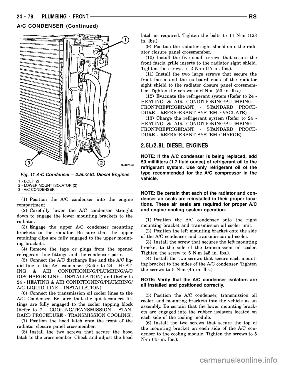
Fig. 11 A/C Condenser ± 2.5L/2.8L Diesel Engines
1 - BOLT (2)
2 - LOWER MOUNT ISOLATOR (2)
3 - A/C CONDENSER
24 - 78 PLUMBING - FRONTRS
A/C CONDENSER (Continued)
Page 2230 of 2339
(7) Remove the tape or plugs from the opened
refrigerant line fittings and the condenser ports.
(8) Connect the A/C discharge line and the A/C liq-
uid line to the A/C condenser (Refer to 24 - HEAT-
ING & AIR CONDITIONING/PLUMBING/A/C
DISCHARGE LINE - INSTALLATION) and (Refer to
24 - HEATING & AIR CONDITIONING/PLUMBING/
A/C LIQUID LINE - INSTALLATION).
(9) Reconnect the hoses to the transmission oil
cooler fittings on the left side of the cooling module
(Refer to 7 - COOLING/TRANSMISSION/TRANS
COOLER LINES - INSTALLATION).
(10) Reposition the hood latch to the front of the
radiator closure panel crossmember.
(11) Install the two screws that secure the hood
latch to the front of the radiator closure panel cross-
member. Check and adjust the hood latch as needed.
Tighten the screws to 14 N´m (123 in. lbs.).
(12) Position the radiator sight shield onto the
radiator closure panel crossmember.
(13) Install the five small screws that secure the
front fascia grille inserts to the radiator sight shield.
Tighten the screws to 2 N´m (17 in. lbs.).
(14) Install the two large screws that secure the
front fascia and the outboard ends of the radiator
sight shield to the radiator closure panel crossmem-
ber. Tighten the screws to 6 N´m (53 in. lbs.).
(15) Evacuate the refrigerant system (Refer to 24 -
HEATING & AIR CONDITIONING/PLUMBING -
FRONT/REFRIGERANT - STANDARD PROCE-
DURE - REFRIGERANT SYSTEM EVACUATE).
(16) Charge the refrigerant system (Refer to 24 -
HEATING & AIR CONDITIONING/PLUMBING -
FRONT/REFRIGERANT - STANDARD PROCE-
DURE - REFRIGERANT SYSTEM CHARGE).
A/C DISCHARGE LINE
REMOVAL
WARNING: REFER TO THE APPLICABLE WARN-
INGS AND CAUTIONS FOR THIS SYSTEM BEFORE
PERFORMING THE FOLLOWING OPERATION (Refer
to 24 - HEATING & AIR CONDITIONING/PLUMBING -
FRONT - WARNING - A/C PLUMBING) and (Refer to
24 - HEATING & AIR CONDITIONING/PLUMBING -
FRONT - CAUTION - A/C PLUMBING).
(1) Recover the refrigerant from the refrigerant
system (Refer to 24 - HEATING & AIR CONDITION-
ING/PLUMBING - FRONT/REFRIGERANT - STAN-
DARD PROCEDURE - REFRIGERANT SYSTEM
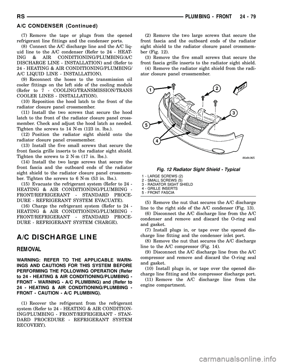
RECOVERY).(2) Remove the two large screws that secure the
front fascia and the outboard ends of the radiator
sight shield to the radiator closure panel crossmem-
ber (Fig. 12).
(3) Remove the five small screws that secure the
front fascia grille inserts to the radiator sight shield.
(4) Remove the radiator sight shield from the radi-
ator closure panel crossmember.
(5) Remove the nut that secures the A/C discharge
line to the right side of the A/C condenser (Fig. 13).
(6) Disconnect the A/C discharge line from the A/C
condenser and remove and discard the O-ring seal
and gasket.
(7) Install plugs in, or tape over the opened dis-
charge line fitting and the condenser inlet port.
(8) Remove the nut that secures the A/C discharge
line to the A/C compressor (Fig. 14).
(9) Disconnect the A/C discharge line from the A/C
compressor and remove and discard the O-ring seal
and gasket.
(10) Install plugs in, or tape over the opened dis-
charge line fitting and the compressor discharge port.
(11) Remove the A/C discharge line from the
engine compartment.
Fig. 12 Radiator Sight Shield - Typical
1 - LARGE SCREWS (2)
2 - SMALL SCREWS (5)
3 - RADIATOR SIGHT SHIELD
4 - GRILLE INSERTS
5 - FRONT FASCIA
RSPLUMBING - FRONT24-79
A/C CONDENSER (Continued)
Page 2332 of 2339
STORAGE BIN GUIDE - INSTALLATION,UNDER SEAT ....................... 23-150
STORAGE BIN GUIDE - REMOVAL, UNDER SEAT ....................... 23-150
STORAGE BIN LOCK/LATCH - INSTALLATION, UNDER SEAT ..........23-150
STORAGE BIN LOCK/LATCH - REMOVAL, UNDER SEAT ....................... 23-150
STRAP - INSTALLATION, CHECK .........23-15
STRAP - INSTALLATION, FRONT SEAT BACK ASSIST ...................... 23-112
STRAP - REMOVAL, CHECK ............23-15
STRAP - REMOVAL, FRONT SEAT BACK ASSIST ........................... 23-112
STRAP - THIRD ROW - FOLD-IN-FLOOR - INSTALLATION, SEAT BACKSTOW .....23-158
STRAP - THIRD ROW - FOLD-IN-FLOOR - REMOVAL, SEAT BACKSTOW .........23-158
STRIKER - INSTALLATION, CENTER ......23-28
STRIKER - INSTALLATION, FUEL FILL DOOR BLOCKER LATCH ...............23-53
STRIKER - INSTALLATION, GLOVE BOX LATCH ............................. 23-66
STRIKER - INSTALLATION, HOLD OPEN LATCH ............................. 23-26
STRIKER - INSTALLATION, LATCH . . 23-19,23-42, 23-64
STRIKER - INSTALLATION, REAR LATCH . . 23-29
STRIKER - REMOVAL, CENTER ..........23-28
STRIKER - REMOVAL, FUEL FILL DOOR BLOCKER LATCH ..................... 23-53
STRIKER - REMOVAL, GLOVE BOX LATCH ............................. 23-66
STRIKER - REMOVAL, HOLD OPEN LATCH ............................. 23-26
STRIKER - REMOVAL, LATCH . 23-19,23-41,23-64
STRIKER - REMOVAL, REAR LATCH ......23-29
STRIPPED THREAD REPAIR - STANDARD PROCEDURE, MANIFOLD ..............9-147
STRUCTURAL ADHESIVE LOCATIONS - FOLD-IN-FLOOR ONLY -
SPECIFICATIONS .................... 23-228
STRUCTURAL ADHESIVE LOCATIONS - SPECIFICATIONS .................... 23-218
STRUCTURAL COLLAR - INSTALLATION ....9-49
STRUCTURAL COLLAR - REMOVAL .......9-49
STRUT - SECOND ROW - FOLD-IN- FLOOR - INSTALLATION, SEAT GAS .....23-139
STRUT - SECOND ROW - FOLD-IN- FLOOR - REMOVAL, SEAT GAS .........23-138
STRUT ASSEMBLY - ASSEMBLY ..........2-23
STRUT ASSEMBLY - DESCRIPTION .......2-19
STRUT ASSEMBLY - DIAGNOSIS AND TESTING ............................ 2-20
STRUT ASSEMBLY - DISASSEMBLY .......2-21
STRUT ASSEMBLY - INSTALLATION .......2-25
STRUT ASSEMBLY - OPERATION .........2-19
STRUT ASSEMBLY - REMOVAL ...........2-20
STUDS - FRONT - INSTALLATION, WHEEL MOUNTING ................... 22-21
STUDS - FRONT - REMOVAL, WHEEL MOUNTING ......................... 22-21
STUDS - REAR - INSTALLATION, WHEEL MOUNTING ......................... 22-22
STUDS - REAR - REMOVAL, WHEEL MOUNTING ......................... 22-22
SUCTION LINE - INSTALLATION . . . 24-107,24-97
SUCTION LINE - REMOVAL .......24-106,24-96
SUN VISOR - INSTALLATION ...........23-99
SUN VISOR - REMOVAL ...............23-99
SUN VISOR SUPPORT - INSTALLATION . . . 23-99
SUN VISOR SUPPORT - REMOVAL .......23-99
SUNROOF - DESCRIPTION ............23-169
SUNROOF ASSEMBLY - INSTALLATION . . 23-173
SUNROOF ASSEMBLY - REMOVAL ......23-173
SUNROOF DIAGNOSIS AND TESTING, DIAGNOSIS AND TESTING ............23-169
SUNROOF GLASS PANEL ADJUSTMENT, ADJUSTMENTS ..................... 23-173
SUNROOF MOTOR - INSTALLATION .....23-174
SUNROOF MOTOR - REMOVAL .........23-174
SUNROOF SWITCH - INSTALLATION .....23-176
SUNROOF SWITCH - REMOVAL ........23-176
SUNSHADE - INSTALLATION ...........23-173
SUNSHADE - REMOVAL ..............23-173
SUPPLEMENTAL CABIN HEATER, DIAGNOSIS AND TESTING ............24-114SUPPLY - PCM OUTPUT - OPERATION, 5
VOLT .............................. 8E-15
SUPPORT - INSTALLATION, LUMBAR ....23-150
SUPPORT - INSTALLATION, SUN VISOR . . . 23-99
SUPPORT - REMOVAL, LUMBAR .......23-150
SUPPORT - REMOVAL, SUN VISOR ......23-99
SUPPORT CYLINDER - INSTALLATION ....23-43
SUPPORT CYLINDER - REMOVAL ........23-42
SUPPORT PLATE - DRUM BRAKE - INSTALLATION ........................ 5-61
SUPPORT PLATE - DRUM BRAKE - REMOVAL ........................... 5-61
SUPPRESSION COMPONENTS - DESCRIPTION, RADIO NOISE ...........8A-15
SUPPRESSION COMPONENTS - OPERATION, RADIO NOISE .............8A-15
SURFACE PREPARATION - STANDARD PROCEDURE, ENGINE GASKET .......9-11,9-87
SUSPENSION - DESCRIPTION, FRONT ......2-2
SUSPENSION - DESCRIPTION, REAR ......2-26
SUSPENSION - OPERATION, FRONT ........2-2
SUSPENSION AND STEERING - DIAGNOSIS AND TESTING ..............2-50
SUSPENSION FASTENER TORQUE, SPECIFICATIONS - FRONT ................2-3
SUSPENSION FASTENER TORQUE, SPECIFICATIONS - REAR ................2-28
SUSPENSION, SPECIAL TOOLS - FRONT ....2-3
SUSPENSION, SPECIAL TOOLS - REAR ....2-28
SWITCH - DESCRIPTION .................8P-5
SWITCH - DESCRIPTION, B-PILLAR ......8N-52
SWITCH - DESCRIPTION, BRAKE FLUID LEVEL .............................. 5-10
SWITCH - DESCRIPTION, BRAKE LAMP ....8L-4
SWITCH - DESCRIPTION, EXTERIOR HANDLE ........................... 8N-10
SWITCH - DESCRIPTION, FULL OPEN ....8N-11,
8N-52
SWITCH - DESCRIPTION, HEATED SEAT . . . 8G-8
SWITCH - DESCRIPTION, HORN ..........8H-4
SWITCH - DESCRIPTION, MEMORY ......8N-36
SWITCH - DESCRIPTION, OIL PRESSURE . 9-144
SWITCH - DESCRIPTION, REAR WINDOW DEFOGGER .................. 8G-4
SWITCH - DESCRIPTION, REAR WIPER/WASHER ..................... 8R-10
SWITCH - DESCRIPTION, SEAT .........8N-34
SWITCH - DIAGNOSIS AND TESTING, BRAKE LAMP ........................ 8L-4
SWITCH - DIAGNOSIS AND TESTING, FAILED PARK ........................ 8R-2
SWITCH - DIAGNOSIS AND TESTING, FRONT WIPER/WASHER ................8R-2
SWITCH - DIAGNOSIS AND TESTING, HEADLAMP ......................... 8L-13
SWITCH - DIAGNOSIS AND TESTING, MULTI-FUNCTION .................... 8L-18
SWITCH - DIAGNOSIS AND TESTING, TRACTION CONTROL ................... 5-94
SWITCH - EXPORT - DESCRIPTION, DOOR CYLINDER LOCK ...............8N-22
SWITCH - EXPORT - DESCRIPTION, POWER FOLDAWAY MIRROR ...........8N-29
SWITCH - EXPORT - INSTALLATION, HOOD AJAR ......................... 8Q-3
SWITCH - EXPORT - INSTALLATION, POWER FOLDAWAY MIRROR ...........8N-30
SWITCH - EXPORT - OPERATION, DOOR CYLINDER LOCK ..................... 8N-22
SWITCH - EXPORT - OPERATION, POWER FOLDAWAY MIRROR ...........8N-29
SWITCH - EXPORT - REMOVAL, HOOD AJAR ............................... 8Q-3
SWITCH - EXPORT - REMOVAL, POWER FOLDAWAY MIRROR .................. 8N-29
SWITCH - INSTALLATION ...............8P-6
SWITCH - INSTALLATION, ADJUSTABLE PEDALS ............................. 5-11
SWITCH - INSTALLATION, B-PILLAR .....8N-52
SWITCH - INSTALLATION, BRAKE FLUID LEVEL .............................. 5-11
SWITCH - INSTALLATION, BRAKE LAMP . . . 8L-5
SWITCH - INSTALLATION, CENTER CONSOLE LAMP ..................... 8L-21
SWITCH - INSTALLATION, EXTERIOR HANDLE ........................... 8N-10
SWITCH - INSTALLATION, FULL OPEN ....8N-11 SWITCH - INSTALLATION, GLOVE BOX
LAMP .............................. 8L-22
SWITCH - INSTALLATION, HEADLAMP ....8L-13
SWITCH - INSTALLATION, IGNITION ......19-19
SWITCH - INSTALLATION, MULTI- FUNCTION .......................... 8L-18
SWITCH - INSTALLATION, OIL PRESSURE ..................... 9-144,9-56
SWITCH - INSTALLATION, SUNROOF ....23-176
SWITCH - INSTALLATION, TRACTION CONTROL ........................... 5-95
SWITCH - INSTALLATION, WASHER FLUID LEVEL ........................ 8R-11
SWITCH - OPERATION .................8P-5
SWITCH - OPERATION, B-PILLAR ........8N-52
SWITCH - OPERATION, BRAKE FLUID LEVEL .............................. 5-10
SWITCH - OPERATION, BRAKE LAMP ......8L-4
SWITCH - OPERATION, EXTERIOR HANDLE ........................... 8N-10
SWITCH - OPERATION, FULL OPEN . 8N-11,8N-52
SWITCH - OPERATION, HEATED SEAT .....8G-9
SWITCH - OPERATION, MEMORY ........8N-36
SWITCH - OPERATION, OIL PRESSURE . . . 9-144
SWITCH - OPERATION, REAR WINDOW DEFOGGER .......................... 8G-4
SWITCH - OPERATION, REAR WIPER/ WASHER ........................... 8R-11
SWITCH - OPERATION, SEAT ...........8N-34
SWITCH - REMOVAL .................... 8P-5
SWITCH - REMOVAL, ADJUSTABLE PEDALS ............................. 5-11
SWITCH - REMOVAL, B-PILLAR .........8N-52
SWITCH - REMOVAL, BRAKE FLUID LEVEL .............................. 5-11
SWITCH - REMOVAL, BRAKE LAMP .......8L-5
SWITCH - REMOVAL, CENTER CONSOLE LAMP .............................. 8L-21
SWITCH - REMOVAL, EXTERIOR HANDLE . 8N-10
SWITCH - REMOVAL, FULL OPEN .......8N-11
SWITCH - REMOVAL, GLOVE BOX LAMP . . 8L-22
SWITCH - REMOVAL, HEADLAMP ........8L-13
SWITCH - REMOVAL, IGNITION .........19-17
SWITCH - REMOVAL, MULTI-FUNCTION . . . 8L-18
SWITCH - REMOVAL, OIL PRESSURE ....9-144,
9-56
SWITCH - REMOVAL, SUNROOF ........23-176
SWITCH - REMOVAL, TRACTION CONTROL ........................... 5-95
SWITCH - REMOVAL, WASHER FLUID LEVEL ............................. 8R-11
SWITCH ASSY - DESCRIPTION, SOLENOID/PRESSURE ..........21-117,21-268
SWITCH ASSY - INSTALLATION, SOLENOID/PRESSURE ..........21-119,21-270
SWITCH ASSY - OPERATION, SOLENOID/ PRESSURE .................. 21-118,21-268
SWITCH ASSY - REMOVAL, SOLENOID/ PRESSURE .................. 21-118,21-269
SWITCH, DIAGNOSIS AND TESTING - DOOR LOCK ........................ 8N-23
SWITCH, DIAGNOSIS AND TESTING - DRIVER HEATED SEAT .................8G-9
SWITCH, DIAGNOSIS AND TESTING - DRIVER SEAT ....................... 8N-34
SWITCH, DIAGNOSIS AND TESTING - MEMORY ........................... 8N-37
SWITCH, DIAGNOSIS AND TESTING - REMOTE ........................... 8N-30
SWITCH, DIAGNOSIS AND TESTING - WINDOW ........................... 8N-63
SWITCH, EXPORT - DOOR CYLINDER LOCK .............................. 8N-22
SWITCHES - DESCRIPTION, REMOTE .....8A-16
SWITCHES - OPERATION, REMOTE ......8A-16
SWITCHES, DIAGNOSIS AND TESTING - REMOTE ........................... 8A-16
SYMBOLS - DESCRIPTION, INTERNATIONAL .......................0-1
SYNCHRONIZING CABLE ADJUSTMENT, INSTALLATION ................ 23-105,23-147
TAIL LAMP - INSTALLATION ............8L-19
TAIL LAMP - REMOVAL ................8L-18
TAIL LAMP UNIT - INSTALLATION .......8L-19
TAIL LAMP UNIT - REMOVAL ...........8L-19
TANK - DESCRIPTION, FUEL ............14-12
TANK - OPERATION, FUEL ..............14-12
RS INDEX31
Description Group-Page Description Group-Page Description Group-Page