belt CHRYSLER VOYAGER 2005 Repair Manual
[x] Cancel search | Manufacturer: CHRYSLER, Model Year: 2005, Model line: VOYAGER, Model: CHRYSLER VOYAGER 2005Pages: 2339, PDF Size: 59.69 MB
Page 496 of 2339
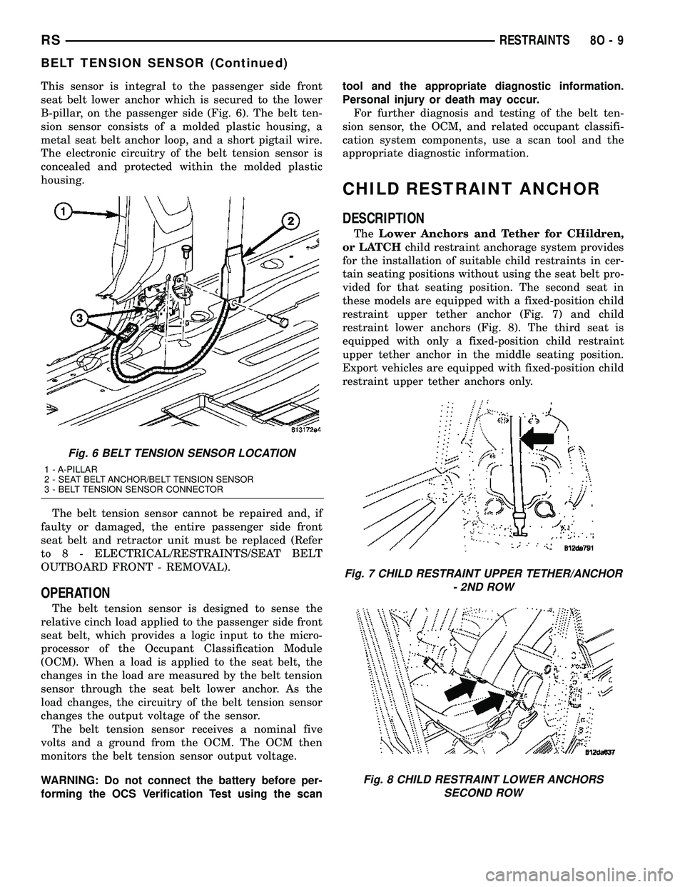
This sensor is integral to the passenger side front
seat belt lower anchor which is secured to the lower
B-pillar, on the passenger side (Fig. 6). The belt ten-
sion sensor consists of a molded plastic housing, a
metal seat belt anchor loop, and a short pigtail wire.
The electronic circuitry of the belt tension sensor is
concealed and protected within the molded plastic
housing.
The belt tension sensor cannot be repaired and, if
faulty or damaged, the entire passenger side front
seat belt and retractor unit must be replaced (Refer
to 8 - ELECTRICAL/RESTRAINTS/SEAT BELT
OUTBOARD FRONT - REMOVAL).
OPERATION
The belt tension sensor is designed to sense the
relative cinch load applied to the passenger side front
seat belt, which provides a logic input to the micro-
processor of the Occupant Classification Module
(OCM). When a load is applied to the seat belt, the
changes in the load are measured by the belt tension
sensor through the seat belt lower anchor. As the
load changes, the circuitry of the belt tension sensor
changes the output voltage of the sensor.
The belt tension sensor receives a nominal five
volts and a ground from the OCM. The OCM then
monitors the belt tension sensor output voltage.
WARNING: Do not connect the battery before per-
forming the OCS Verification Test using the scantool and the appropriate diagnostic information.
Personal injury or death may occur.
For further diagnosis and testing of the belt ten-
sion sensor, the OCM, and related occupant classifi-
cation system components, use a scan tool and the
appropriate diagnostic information.
CHILD RESTRAINT ANCHOR
DESCRIPTION
TheLower Anchors and Tether for CHildren,
or LATCHchild restraint anchorage system provides
for the installation of suitable child restraints in cer-
tain seating positions without using the seat belt pro-
vided for that seating position. The second seat in
these models are equipped with a fixed-position child
restraint upper tether anchor (Fig. 7) and child
restraint lower anchors (Fig. 8). The third seat is
equipped with only a fixed-position child restraint
upper tether anchor in the middle seating position.
Export vehicles are equipped with fixed-position child
restraint upper tether anchors only.
Fig. 6 BELT TENSION SENSOR LOCATION
1 - A-PILLAR
2 - SEAT BELT ANCHOR/BELT TENSION SENSOR
3 - BELT TENSION SENSOR CONNECTOR
Fig. 7 CHILD RESTRAINT UPPER TETHER/ANCHOR
- 2ND ROW
Fig. 8 CHILD RESTRAINT LOWER ANCHORS
SECOND ROW
RSRESTRAINTS8O-9
BELT TENSION SENSOR (Continued)
Page 497 of 2339
The second row seats have lower anchors for each
rear outboard seating position (Fig. 8). These anchors
are welded to the seat cushion frame. They are each
accessed from the front of their respective seats, at
each side where the seat back meets the seat cush-
ion. These lower anchors cannot be adjusted or
repaired and, if faulty or damaged, the seat must be
replaced as a unit.
WARNING: During, and following, any child restraint
anchor service, due to impact event or vehicle
repair, carefully inspect all mounting hardware,
tether straps and anchors for proper installation,
operation, or damage. If a child restraint anchor is
found damaged in any way, the anchor must be
replaced with the seat assembly. Failure to do so
could result in personal injury or death.
REAR SEAT DELETE
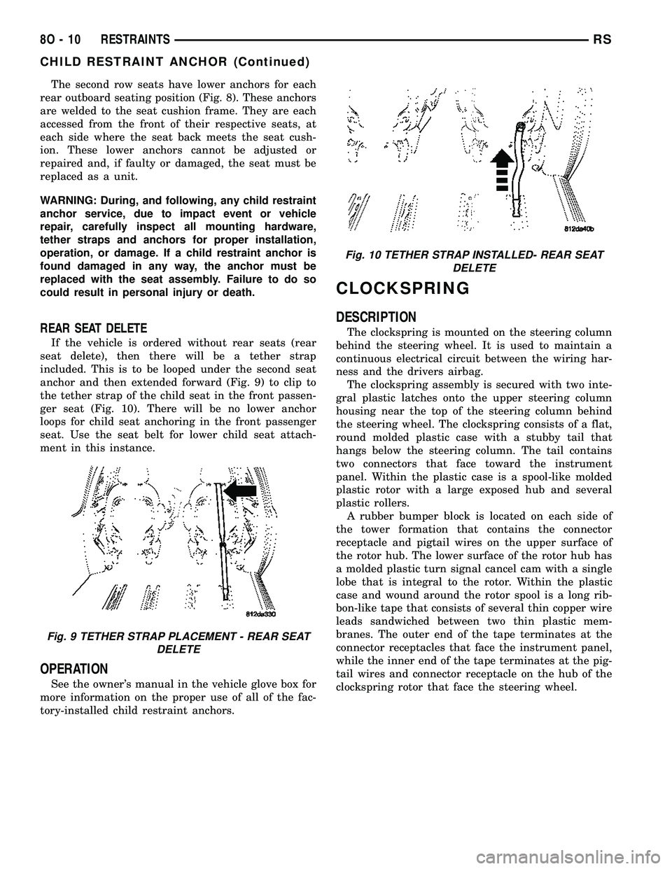
If the vehicle is ordered without rear seats (rear
seat delete), then there will be a tether strap
included. This is to be looped under the second seat
anchor and then extended forward (Fig. 9) to clip to
the tether strap of the child seat in the front passen-
ger seat (Fig. 10). There will be no lower anchor
loops for child seat anchoring in the front passenger
seat. Use the seat belt for lower child seat attach-
ment in this instance.
OPERATION
See the owner's manual in the vehicle glove box for
more information on the proper use of all of the fac-
tory-installed child restraint anchors.
CLOCKSPRING
DESCRIPTION
The clockspring is mounted on the steering column
behind the steering wheel. It is used to maintain a
continuous electrical circuit between the wiring har-
ness and the drivers airbag.
The clockspring assembly is secured with two inte-
gral plastic latches onto the upper steering column
housing near the top of the steering column behind
the steering wheel. The clockspring consists of a flat,
round molded plastic case with a stubby tail that
hangs below the steering column. The tail contains
two connectors that face toward the instrument
panel. Within the plastic case is a spool-like molded
plastic rotor with a large exposed hub and several
plastic rollers.
A rubber bumper block is located on each side of
the tower formation that contains the connector
receptacle and pigtail wires on the upper surface of
the rotor hub. The lower surface of the rotor hub has
a molded plastic turn signal cancel cam with a single
lobe that is integral to the rotor. Within the plastic
case and wound around the rotor spool is a long rib-
bon-like tape that consists of several thin copper wire
leads sandwiched between two thin plastic mem-
branes. The outer end of the tape terminates at the
connector receptacles that face the instrument panel,
while the inner end of the tape terminates at the pig-
tail wires and connector receptacle on the hub of the
clockspring rotor that face the steering wheel.
Fig. 9 TETHER STRAP PLACEMENT - REAR SEAT
DELETE
Fig. 10 TETHER STRAP INSTALLED- REAR SEAT
DELETE
8O - 10 RESTRAINTSRS
CHILD RESTRAINT ANCHOR (Continued)
Page 503 of 2339
INSTALLATION
(1) Position curtain airbag over retaining holes in
roof rail and firmly snap into place (Fig. 17).
(2) Install the curtain airbag retaining bolts (Fig.
17).
(3) Engage the side curtain airbag front tether in
the A-pillar and install retaining bolt (Fig. 16).
(4) Install the bolt in the curtain airbag inflator
mounting bracket (Fig. 18).
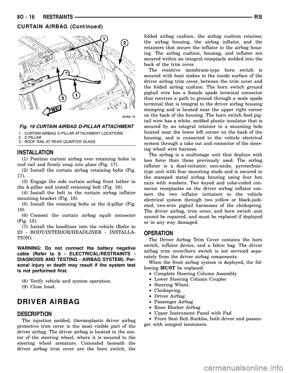
(5) Install the retaining bolts at the d-pillar (Fig.
19).
(6) Connect the curtain airbag squib connector
(Fig. 15).
(7) Install the headliner into the vehicle (Refer to
23 - BODY/INTERIOR/HEADLINER - INSTALLA-
TION).
WARNING: Do not connect the battery negative
cable (Refer to 8 - ELECTRICAL/RESTRAINTS -
DIAGNOSIS AND TESTING - AIRBAG SYSTEM). Per-
sonal injury or death may result if the system test
is not performed first.
(8) Verify vehicle and system operation.
(9) Close hood.
DRIVER AIRBAG
DESCRIPTION
The injection molded, thermoplastic driver airbag
protective trim cover is the most visible part of the
driver airbag. The driver airbag is located in the cen-
ter of the steering wheel, where it is secured to the
steering wheel armature. Concealed beneath the
driver airbag trim cover are the horn switch, thefolded airbag cushion, the airbag cushion retainer,
the airbag housing, the airbag inflator, and the
retainers that secure the inflator to the airbag hous-
ing. The airbag cushion, housing, and inflator are
secured within an integral receptacle molded into the
back of the trim cover.
The resistive membrane-type horn switch is
secured with heat stakes to the inside surface of the
driver airbag trim cover, between the trim cover and
the folded airbag cushion. The horn switch ground
pigtail wire has a female spade terminal connector
that receives a path to ground through a male spade
terminal that is integral to the driver airbag housing
stamping and is located near the upper right corner
on the back of the housing. The horn switch feed pig-
tail wire has a white, molded plastic insulator that is
secured by an integral retainer to a mounting hole
located near the lower left corner on the back of the
housing, and is connected to the vehicle electrical
system through a take out and connector of the steer-
ing wheel wire harness.
The airbag is a multistage unit that deploys with
less force than those previously used. The airbag
inflator is a dual-initiator, non-azide, pyrotechnic-
type unit with four mounting studs and is secured to
the stamped metal airbag housing using four hex
nuts with washers. Two keyed and color-coded con-
nector receptacles on the driver airbag inflator con-
nect the two inflator initiators to the vehicle
electrical system through two yellow or black-jack-
eted, two-wire pigtail harnesses of the clockspring.
The driver airbag, trim cover, and horn switch unit
cannot be repaired, and must be replaced if deployed
or in any way damaged.
OPERATION
The Driver Airbag Trim Cover contains the horn
switch, inflator device, and a fabric bag. The driver
airbag trim cover/horn switch is not serviced sepa-
rately from the driver airbag components.
When the front airbag system is deployed, the fol-
lowingMUSTbe replaced:
²Complete Steering Column Assembly
²Lower Steering Column Coupler
²Steering Wheel.
²Clockspring.
²Driver Airbag
²Passenger Airbag
²Knee Blocker Airbag
²Upper Instrument Panel with Pad
²Front Seat Belt Buckles, both driver and passen-
ger with integral tensioners.
Fig. 19 CURTAIN AIRBAG D-PILLAR ATTACHMENT
1 - CURTAIN AIRBAG D-PILLAR ATTACHMENT LOCATIONS
2 - D-PILLAR
3 - ROOF RAIL AT REAR QUARTER GLASS
8O - 16 RESTRAINTSRS
CURTAIN AIRBAG (Continued)
Page 506 of 2339

SIDE IMPACT SENSORS
Three side impact sensors (Fig. 22) are used on
each side of the vehicle. These sensors are mounted
remotely from the bi-directional safing sensor that is
internal to the Occupant Restraint Controller (ORC).
The side and front impact sensors are identical in
construction and calibration and each impact sensor
is secured with two screws. Each side impact sensor
is secured with two screws. The first row side impact
sensor is located in the B-pillar, just above the front
seat belt retractor (Fig. 23). The second row side
impact sensor is located in the sliding door opening,in the lower door track area (Fig. 23). The third row
side impact sensor is located behind the quarter trim
panel, above the rear tire wheel well, between the C
and D-pillars (Fig. 23).
The impact sensor housing has an integral connec-
tor. A cavity in the center of the molded black plastic
impact sensor housing contains the electronic cir-
cuitry of the sensor which includes an electronic com-
munication chip and an electronic impact sensor.
Potting material fills the cavity to seal and protect
the internal electronic circuitry and components. The
side impact sensors are each connected to the vehicle
electrical system through a connector of the body
harness.
The side impact sensors cannot be repaired or
adjusted. If damaged or faulty, they must be
replaced. Refer to the proper body diagnostic infor-
mation for diagnosis and testing.
REMOVAL
FRONT IMPACT SENSOR
The right and left front impact sensors are
mounted identically on the front rail tips.
(1) Open hood, disconnect and isolate the battery
negative cable.
(2)
WARNING: Wait two minutes for the airbag system
reserve capacitor to discharge before beginning
any airbag system or component service. Failure to
do so may result in accidental airbag deployment,
personal injury or death.
Fig. 23 SIDE IMPACT SENSOR LOCATION
1 - FRONT ROW SIDE IMPACT SENSOR 3 - THIRD ROW SIDE IMPACT SENSOR
2 - SECOND ROW SIDE IMPACT SENSOR
Fig. 22 SIDE IMPACT SENSOR
RSRESTRAINTS8O-19
IMPACT SENSOR (Continued)
Page 512 of 2339
OCCUPANT CLASSIFICATION
MODULE
DESCRIPTION
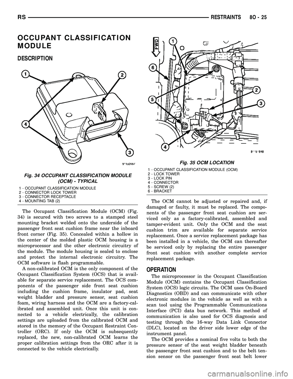
The Occupant Classification Module (OCM) (Fig.
34) is secured with two screws to a stamped steel
mounting bracket welded onto the underside of the
passenger front seat cushion frame near the inboard
front corner (Fig. 35). Concealed within a hollow in
the center of the molded plastic OCM housing is a
microprocessor and the other electronic circuitry of
the module. The module housing is sealed to enclose
and protect the internal electronic circuitry. The
OCM software is flash programmable.
A non-calibrated OCM is the only component of the
Occupant Classification System (OCS) that is avail-
able for separate service replacement. The OCS com-
ponents of the passenger side front seat cushion
including the cushion frame, insulator pad, seat
weight bladder and pressure sensor, seat cushion
foam, wiring harness and the OCM are a factory-cal-
ibrated and assembled unit. Once this unit is con-
nected to a vehicle electrically, the calibration
settings are uploaded from the calibrated OCM and
stored in the memory of the Occupant Restraint Con-
troller (ORC). If only the OCM is subsequently
replaced, the new, non-calibrated OCM learns the
proper calibration settings from the ORC after it is
connected to the vehicle electrically.The OCM cannot be adjusted or repaired and, if
damaged or faulty, it must be replaced. The compo-
nents of the passenger front seat cushion are ser-
viced only as a factory-calibrated, assembled and
tamper-evident unit. Only the OCM and the seat
cushion trim are available for separate service
replacement. Once a service replacement package has
been installed in a vehicle, the OCM can thereafter
be serviced only by replacing the entire passenger
front seat cushion with another complete service
replacement package.
OPERATION
The microprocessor in the Occupant Classification
Module (OCM) contains the Occupant Classification
System (OCS) logic circuits. The OCM uses On-Board
Diagnostics (OBD) and can communicate with other
electronic modules in the vehicle as well as with a
scan tool using the Programmable Communications
Interface (PCI) data bus network. This method of
communication is also used for OCS diagnosis and
testing through the 16-way Data Link Connector
(DLC), located on the driver side lower edge of the
instrument panel.
The OCM provides a nominal five volts to both the
pressure sensor of the seat weight bladder beneath
the passenger front seat cushion and to the belt ten-
sion sensor on the passenger front seat belt lower
Fig. 34 OCCUPANT CLASSIFICATION MODULE
(OCM) - TYPICAL
1 - OCCUPANT CLASSIFICATION MODULE
2 - CONNECTOR LOCK TOWER
3 - CONNECTOR RECEPTACLE
4 - MOUNTING TAB (2)
Fig. 35 OCM LOCATION
1 - OCCUPANT CLASSIFICATION MODULE (OCM)
2 - LOCK TOWER
3 - LOCK PIN
4 - CONNECTOR
5 - SCREW (2)
6 - BRACKET
RSRESTRAINTS8O-25
Page 513 of 2339
anchor. The OCM then monitors the return voltage
from each of the sensors. The bladder pressure sen-
sor input allows the OCM to determine whether the
passenger front seat is occupied and the relative size
of the occupant by providing a weight-sensing refer-
ence to the load on the seat cushion. The belt tension
sensor provides an additional logic input to the OCM
microprocessor that allows it to distinguish between
the lower seat belt cinch loads of a belted occupant
and the higher loads associated with a belted child
seat.
Pre-programmed decision algorithms and OCS cal-
ibration allow the OCM microprocessor to determine
when the seat cushion load as signaled by the blad-
der pressure sensor and the seat belt cinch load as
signaled by the belt tension sensor indicate that pas-
senger airbag protection is appropriate. When the
programmed conditions are met, the OCM sends the
proper electronic occupant classification messages
over the PCI data bus to the Occupant Restraint
Controller (ORC), and the ORC enables or disables
the deployment circuits for the passenger front sup-
plemental restraints. The ORC also provides a con-
trol output for the Passenger Airbag Disabled (PAD)
indicator in the instrument panel center stack, based
upon the electronic occupant classification messages
it receives from the OCM.
The OCM microprocessor continuously monitors all
of the OCS electrical circuits and components to
determine the system readiness. If the OCM detects
a monitored system fault, it sets an active and stored
Diagnostic Trouble Code (DTC) and sends the appro-
priate electronic messages to the ORC over the PCI
data bus. Then the ORC sets a DTC and sends mes-
sages to control the airbag indicator operation
accordingly. An active fault only remains for the
duration of the fault, or in some cases for the dura-
tion of the current ignition switch cycle, while a
stored fault causes a DTC to be stored in memory by
the OCM and the ORC. For some DTC's, if a fault
does not recur for a number of ignition cycles, the
OCM will automatically erase the stored DTC. For
other internal faults, the stored DTC is latched for-
ever.
The OCM receives battery current from an IPM
high side driver (Run/Start). The OCM receives
ground through a ground circuit of the body wire
harness, which it shares with the ORC. These con-
nections allow the OCM to be operational whenever
the ignition switch is in the Start or ON positions.
To diagnose and test the OCS, use a scan tool and
the appropriate diagnostic information.
REMOVAL
Once any of the original factory-installed compo-
nents except the Occupant Classification Module(OCM) have been replaced with the service replace-
ment package components, the OCM can only be ser-
viced by replacing the entire passenger front seat
cushion unit with another complete service replace-
ment package (Refer to 23 - BODY/SEATS/SEAT
CUSHION - FRONT - REMOVAL).
WARNING: Never replace both the Occupant
Restraint Controller (ORC) and the Occupant Clas-
sification Module (OCM) at the same time. If both
require replacement, replace one, then perform the
Airbag System test (Refer to 8 - ELECTRICAL/RE-
STRAINTS - DIAGNOSIS AND TESTING - AIRBAG
SYSTEM) before replacing the other. Both the ORC
and the OCM store Occupant Classification System
(OCS) calibration data, which they transfer to one
another when one of them is replaced. If both are
replaced at the same time, an irreversible fault will
be set in both modules and the OCS may malfunc-
tion and result in personal injury or death.
(1) Disconnect and isolate the battery negative
cable.
(2)
WARNING: Wait two minutes for the airbag system
reserve capacitor to discharge before beginning
any airbag system or component service. Failure to
do so may result in accidental airbag deployment,
personal injury or death.
(3) Reach under the front edge of the passenger
side front seat cushion to access and remove the lock
pin from the connector lock tower on the Occupant
Classification Module (OCM) (Fig. 36).
(4) Disconnect the passenger front seat wire har-
ness connector for the OCM.
(5) Remove the two screws that secure the OCM to
the OCM bracket.
(6) Remove the OCM from under the passenger
front seat.
INSTALLATION
WARNING: To avoid personal injury or death on
vehicles equipped with the Occupant Classification
System (OCS), only the Occupant Classification
Module (OCM) and the seat cushion trim may be
serviced separately. All other components of the
passenger front seat cushion must be serviced only
as a complete factory-calibrated, assembled and
tamper-evident service replacement package.
Once any of the original factory-installed compo-
nents except the OCM have been replaced with the
service replacement package components, the OCM
can only be serviced by replacing the entire passen-
8O - 26 RESTRAINTSRS
OCCUPANT CLASSIFICATION MODULE (Continued)
Page 515 of 2339
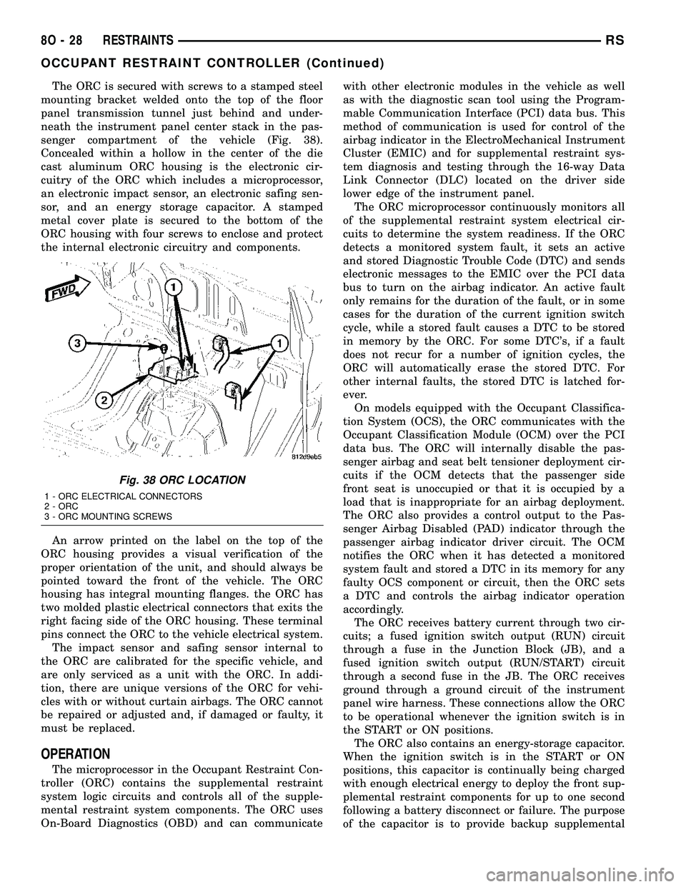
The ORC is secured with screws to a stamped steel
mounting bracket welded onto the top of the floor
panel transmission tunnel just behind and under-
neath the instrument panel center stack in the pas-
senger compartment of the vehicle (Fig. 38).
Concealed within a hollow in the center of the die
cast aluminum ORC housing is the electronic cir-
cuitry of the ORC which includes a microprocessor,
an electronic impact sensor, an electronic safing sen-
sor, and an energy storage capacitor. A stamped
metal cover plate is secured to the bottom of the
ORC housing with four screws to enclose and protect
the internal electronic circuitry and components.
An arrow printed on the label on the top of the
ORC housing provides a visual verification of the
proper orientation of the unit, and should always be
pointed toward the front of the vehicle. The ORC
housing has integral mounting flanges. the ORC has
two molded plastic electrical connectors that exits the
right facing side of the ORC housing. These terminal
pins connect the ORC to the vehicle electrical system.
The impact sensor and safing sensor internal to
the ORC are calibrated for the specific vehicle, and
are only serviced as a unit with the ORC. In addi-
tion, there are unique versions of the ORC for vehi-
cles with or without curtain airbags. The ORC cannot
be repaired or adjusted and, if damaged or faulty, it
must be replaced.
OPERATION
The microprocessor in the Occupant Restraint Con-
troller (ORC) contains the supplemental restraint
system logic circuits and controls all of the supple-
mental restraint system components. The ORC uses
On-Board Diagnostics (OBD) and can communicatewith other electronic modules in the vehicle as well
as with the diagnostic scan tool using the Program-
mable Communication Interface (PCI) data bus. This
method of communication is used for control of the
airbag indicator in the ElectroMechanical Instrument
Cluster (EMIC) and for supplemental restraint sys-
tem diagnosis and testing through the 16-way Data
Link Connector (DLC) located on the driver side
lower edge of the instrument panel.
The ORC microprocessor continuously monitors all
of the supplemental restraint system electrical cir-
cuits to determine the system readiness. If the ORC
detects a monitored system fault, it sets an active
and stored Diagnostic Trouble Code (DTC) and sends
electronic messages to the EMIC over the PCI data
bus to turn on the airbag indicator. An active fault
only remains for the duration of the fault, or in some
cases for the duration of the current ignition switch
cycle, while a stored fault causes a DTC to be stored
in memory by the ORC. For some DTC's, if a fault
does not recur for a number of ignition cycles, the
ORC will automatically erase the stored DTC. For
other internal faults, the stored DTC is latched for-
ever.
On models equipped with the Occupant Classifica-
tion System (OCS), the ORC communicates with the
Occupant Classification Module (OCM) over the PCI
data bus. The ORC will internally disable the pas-
senger airbag and seat belt tensioner deployment cir-
cuits if the OCM detects that the passenger side
front seat is unoccupied or that it is occupied by a
load that is inappropriate for an airbag deployment.
The ORC also provides a control output to the Pas-
senger Airbag Disabled (PAD) indicator through the
passenger airbag indicator driver circuit. The OCM
notifies the ORC when it has detected a monitored
system fault and stored a DTC in its memory for any
faulty OCS component or circuit, then the ORC sets
a DTC and controls the airbag indicator operation
accordingly.
The ORC receives battery current through two cir-
cuits; a fused ignition switch output (RUN) circuit
through a fuse in the Junction Block (JB), and a
fused ignition switch output (RUN/START) circuit
through a second fuse in the JB. The ORC receives
ground through a ground circuit of the instrument
panel wire harness. These connections allow the ORC
to be operational whenever the ignition switch is in
the START or ON positions.
The ORC also contains an energy-storage capacitor.
When the ignition switch is in the START or ON
positions, this capacitor is continually being charged
with enough electrical energy to deploy the front sup-
plemental restraint components for up to one second
following a battery disconnect or failure. The purpose
of the capacitor is to provide backup supplemental
Fig. 38 ORC LOCATION
1 - ORC ELECTRICAL CONNECTORS
2 - ORC
3 - ORC MOUNTING SCREWS
8O - 28 RESTRAINTSRS
OCCUPANT RESTRAINT CONTROLLER (Continued)
Page 516 of 2339

restraint system protection in case there is a loss of
battery current supply to the ORC during an impact.
Two sensors are contained within the ORC, an
electronic impact sensor and a safing sensor. The
ORC also monitors inputs from eight remote impact
sensors. Two front impact sensors are located on each
outboard side of the lower radiator support, and
three side impact sensors are located on each side of
the vehicle at the B-pillar, in the lower sliding door
opening in front of the C-pillar, and over the rear
wheel well between the C and D-pillars. The elec-
tronic impact sensors are accelerometers that sense
the rate of vehicle deceleration, which provides veri-
fication of the direction and severity of an impact.
The safing sensor is an electronic accelerometer
sensor within the ORC that provides an additional
logic input to the ORC microprocessor. The safing
sensor is used to verify the need for a supplemental
restraint deployment by detecting impact energy of a
lesser magnitude than that of the primary electronic
impact sensors, and must exceed a safing threshold
in order for the airbags to deploy. Vehicles equipped
with curtain airbags, there is a second safing sensor
within the ORC to provide confirmation to the ORC
microprocessor of side impact forces. This second saf-
ing sensor is a bi-directional unit that detects impact
forces from either side of the vehicle.
Pre-programmed decision algorithms in the ORC
microprocessor determine when the deceleration rate
as signaled by the impact sensors and the safing sen-
sors indicate an impact that is severe enough to
require supplemental restraint system protection
and, based upon the severity of the monitored
impact, determines the level of front airbag deploy-
ment force required for each front seating position.
When the programmed conditions are met, the ORC
sends the proper electrical signals to deploy the dual
multistage front airbags at the programmed force
levels, the front seat belt tensioners and, if the vehi-
cle is so equipped, either curtain airbag. For vehicles
equipped with the OCS, the passenger front airbag
and seat belt tensioner will be deployed by the ORC
only if enabled by the OCM messages (PAD indicator
OFF) at the time of the impact.
To diagnose and test the ORC and all airbag sys-
tem components, use a scan tool and the appropriate
diagnostic information.
REMOVAL
WARNING: Never replace both the Occupant
Restraint Controller (ORC) and the Occupant Clas-
sification Module (OCM) at the same time. If both
require replacement, replace one, then perform the
Airbag System test (Refer to 8 - ELECTRICAL/RE-
STRAINTS - DIAGNOSIS AND TESTING - AIRBAGSYSTEM) before replacing the other. Both the ORC
and the OCM store Occupant Classification System
(OCS) calibration data, which they transfer to one
another when one of them is replaced. If both are
replaced at the same time, an irreversible fault will
be set in both modules and the OCS may malfunc-
tion and result in personal injury or death.
(1) Disconnect and isolate the battery negative
cable.
(2)
WARNING: Wait two minutes for the airbag system
reserve capacitor to discharge before beginning
any airbag system or component service. Failure to
do so may result in accidental airbag deployment,
personal injury or death.
(3) Remove storage bin from instrument panel
(Refer to 23 - BODY/INSTRUMENT PANEL/STOR-
AGE BIN - REMOVAL).
(4) Remove three bolts holding ORC to floor
bracket (Fig. 39).
(5) Disconnect the wire connectors from the ORC
(Fig. 39).
(6) Remove the ORC from vehicle.
INSTALLATION
WARNING: Do not install ORC if mounting location
is deformed or damaged. This will cause the ORC
to be improperly located and could result in occu-
pant personal injury or death.
WARNING: Use correct screws when installing the
ORC.
Fig. 39 ORC - REMOVE/INSTALL
1 - ORC ELECTRICAL CONNECTORS
2 - ORC
3 - ORC MOUNTING SCREWS
RSRESTRAINTS8O-29
OCCUPANT RESTRAINT CONTROLLER (Continued)
Page 520 of 2339
(28) Install two right side nuts at instrument
panel center stack support to floor.
(29) Install two left side nuts at instrument panel
center stack support to floor.
(30) Connect the two wiring connectors to lower
instrument panel cubby bin at bottom of center stack
and install six screws.
(31) Align left side upper A-pillar trim over retain-
ing slots and firmly snap into place.
(32) Install four nuts at brake pedal support
bracket to instrument panel.
(33) Align left A-pillar lower extension trim over
retaining slots and firmly snap into place.
(34) Install knee blocker and retaining screws.
(35) Install Data Link Connector (DLC) into bot-
tom of knee blocker.
(36) Align parking brake lever and snap into place
on knee blocker reinforcement.
(37) Install lower steering column cover and four
retaining screws
(38) Align left cowl panel over retaining slots and
firmly snap into place.
(39) Align left front door sill plate over retaining
slots and firmly snap into place.
(40) Install center console bin between front seats.
WARNING: Do not connect the battery negative
cable (Refer to 8 - ELECTRICAL/RESTRAINTS -
DIAGNOSIS AND TESTING - AIRBAG SYSTEM). Per-
sonal injury or death may result if the system test
is not performed first.
(41) Close hood.
(42) Verify system and vehicle operation.
PASSENGER AIRBAG
DISABLED INDICATOR
DESCRIPTION
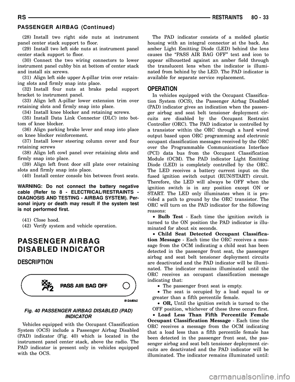
Vehicles equipped with the Occupant Classification
System (OCS) include a Passenger Airbag Disabled
(PAD) indicator (Fig. 40) which is located in the
instrument panel center stack, above the radio. The
PAD indicator is present only in vehicles equipped
with the OCS.The PAD indicator consists of a molded plastic
housing with an integral connector at the back. An
amber Light Emitting Diode (LED) behind the lens
causes the ªPASS AIR BAG OFFº text and icon to
appear silhouetted against an amber field through
the translucent lens when the indicator is illumi-
nated from behind by the LED. The PAD indicator is
available for separate service replacement.
OPERATION
In vehicles equipped with the Occupant Classifica-
tion System (OCS), the Passenger Airbag Disabled
(PAD) indicator gives an indication when the passen-
ger airbag and seat belt tensioner deployment cir-
cuits are disabled by the Occupant Restraint
Controller (ORC). The PAD indicator is controlled by
a transistor within the ORC through a hard wired
output based upon ORC programming and electronic
occupant classification messages received by the ORC
over the Programmable Communications Interface
(PCI) data bus from the Occupant Classification
Module (OCM). The PAD indicator Light Emitting
Diode (LED) is completely controlled by the ORC.
The LED receives a battery current input on the
fused ignition switch output (RUN/START) circuit.
Therefore, the LED will always be OFF when the
ignition switch is in any position except ON or
START. The LED only illuminates when it is pro-
vided a path to ground by the ORC transistor. The
ORC will turn on the PAD indicator for the following
reasons:
²Bulb Test- Each time the ignition switch is
turned to the ON position the PAD indicator is illu-
minated for about six seconds.
²Child Seat Detected Occupant Classifica-
tion Message- Each time the ORC receives a mes-
sage from the OCM indicating a child seat has been
detected in the passenger front seat, the passenger
airbag and seat belt tensioner deployment circuits
are deactivated and the PAD indicator will be illumi-
nated. The indicator remains illuminated until the
ORC receives an occupant classification message
indicating that:
²The passenger front seat is empty.
²The seat is occupied by a load equal to or
greater than a fifth percentile female.
²OR,Until the ignition switch is turned to the
OFF position, whichever of these three occurs first.
²Load Less Than Fifth Percentile Female
Occupant Classification Message- Each time the
ORC receives a message from the OCM indicating
that a load less than a fifth percentile female has
been detected in the passenger front seat, the pas-
senger airbag and seat belt tensioner deployment cir-
cuits are deactivated and the PAD indicator will be
illuminated. The indicator remains illuminated until:
Fig. 40 PASSENGER AIRBAG DISABLED (PAD)
INDICATOR
RSRESTRAINTS8O-33
PASSENGER AIRBAG (Continued)
Page 521 of 2339

²The ORC receives an occupant classification
message indicating that the passenger front seat is
empty.
²The seat is occupied by a load equal to or
greater than a fifth percentile female.
²OR, until the ignition switch is turned to the
OFF position, whichever of these three occurs first.
²Load Undetermined Occupant Classifica-
tion Message- Each time the ORC receives a mes-
sage from the OCM indicating that a load cannot be
determined in the passenger front seat, the passen-
ger airbag and seat belt tensioner deployment cir-
cuits are deactivated and the PAD indicator will be
illuminated. The indicator remains illuminated until:
²The ORC receives an occupant classification
message indicating that the passenger front seat is
empty.
²The seat is occupied by a load equal to or
greater than a fifth percentile female.
²OR, until the ignition switch is turned to the
OFF position, whichever of these three occurs first.
²Communication Error- If the ORC receives
invalid occupant classification messages or no mes-
sages from the OCM, the PAD indicator is illumi-
nated. The indicator remains illuminated until:
²The ORC receives an occupant classification
message indicating that the passenger front seat is
empty.
²The seat is occupied by a load equal to or
greater than a fifth percentile female.
²OR, until the ignition switch is turned to the
OFF position, whichever of these three occurs first.
The ORC continually monitors the occupant classi-
fication messages from the OCM to decide whether
the passenger airbag and seat belt tensioner deploy-
ment circuits should be activated or deactivated.
Note that there may be several seconds of delay
between changes in the detected occupant status and
PAD indications. This is a programmed feature of the
OCM used to prevent a flashing indicator condition
resulting from the normal shifting of occupant weight
on the passenger seat cushion. The ORC then pro-
vides the proper control output to turn the PAD indi-
cator ON or OFF.
The ORC will store a Diagnostic Trouble Code
(DTC) for any malfunction it detects. For proper
diagnosis of the OCM, the ORC, the PCI data bus, or
the electronic message inputs to the ORC that con-
trol the PAD indicator, use a scan tool and the appro-
priate diagnostic information.REMOVAL
(1) Open hood.
(2) Disconnect and isolate the battery negative
cable.
(3)
WARNING: Wait two minutes for the airbag system
reserve capacitor to discharge before beginning
any airbag system or component service. Failure to
do so may result in accidental airbag deployment,
personal injury or death.
(4) Remove instrument panel center bezel (Refer to
23 - BODY/INSTRUMENT PANEL/INSTRUMENT
PANEL CENTER BEZEL - REMOVAL).
(5) From the back of the center bezel, depress the
two latches toward the indicator housing and push
the indicator out through the face of the center bezel.
INSTALLATION
(1) From the face of the instrument panel center
bezel, align the Passenger Airbag Disabled (PAD)
indicator housing with the mounting hole.
(2) Firmly push the indicator into the center bezel
until the two latches are fully engaged on the back of
the cap and are snapped in.
(3) Install the instrument panel center bezel (Refer
to 23 - BODY/INSTRUMENT PANEL/INSTRUMENT
PANEL CENTER BEZEL - INSTALLATION).
WARNING: Do not connect the battery negative
cable (Refer to 8 - ELECTRICAL/RESTRAINTS -
DIAGNOSIS AND TESTING - AIRBAG SYSTEM). Per-
sonal injury or death may result if the system test
is not performed first.
WARNING: Following successful completion of the
Airbag System test procedure, the Occupant Classi-
fication System Verification Test must be done
using a scan tool and the appropriate diagnostic
information.
(4) Close hood.
(5) Verify system and vehicle operation.
8O - 34 RESTRAINTSRS
PASSENGER AIRBAG DISABLED INDICATOR (Continued)