fuse box CHRYSLER VOYAGER 2005 Service Manual
[x] Cancel search | Manufacturer: CHRYSLER, Model Year: 2005, Model line: VOYAGER, Model: CHRYSLER VOYAGER 2005Pages: 2339, PDF Size: 59.69 MB
Page 461 of 2339
upper half of the track unit. Each motor moves the
seat adjuster through a combination of worm-drive
gearboxes and screw-type drive units. The horizontal
adjustment motor moves the seat track in the for-
ward and aft directions. The recliner adjustment
motor moves the seat back in the forward and rear-
ward directions.
The power seat track unit cannot be repaired, and
is serviced only as a complete unit. If any component
in this unit is faulty or damaged, the entire power
seat track unit must be replaced.
OPERATION
When the power seat switch control knob or knobs
are actuated, a battery feed and a ground path are
applied through the switch contacts to the power seat
track or recliner adjuster motor. The selected
adjuster motor operates to move the seat track or
recliner through its drive unit in the selected direc-
tion until the switch is released, or until the travel
limit of the adjuster is reached. When the switch is
moved in the opposite direction, the battery feed and
ground path to the motor are reversed through the
switch contacts. This causes the adjuster motor to
run in the opposite direction.
No power seat switch should be held applied in any
direction after the adjuster has reached its travel
limit. The power seat adjuster motors each contain a
self-resetting circuit breaker to protect them from
overload. However, consecutive or frequent resetting
of the circuit breaker must not be allowed to con-
tinue, or the motor may be damaged.
DIAGNOSIS AND TESTING
POWER SEAT TRACK
WARNING: SOME VEHICLES ARE EQUIPPED WITH
SEATBACK MOUNTED AIRBAGS. BEFORE
ATTEMPTING TO DIAGNOSE OR SERVICE ANY
SEAT OR POWER SEAT SYSTEM COMPONENT
YOU MUST FIRST DISCONNECT AND ISOLATE THE
BATTERY NEGATIVE CABLE. THEN WAIT TWO MIN-
UTES FOR THE SYSTEM CAPACITOR TO DIS-
CHARGE BEFORE FURTHER SYSTEM SERVICE.
THIS IS THE ONLY SURE WAY TO DISABLE THE
AIRBAG SYSTEM. FAILURE TO DO SO COULD
RESULT IN ACCIDENTAL AIRBAG DEPLOYMENT
AND POSSIBLE PERSONAL INJURY.
Actuate the power seat switch to move the power
seat track adjusters in each direction. The power seat
track adjusters should move in each of the selected
directions. If a power seat track adjuster operates in
one direction only, move the adjuster a short distance
in the opposite direction and test again to be certainthat the adjuster is not at its travel limit. If the
power seat track adjuster still operates in one direc-
tion only, (Refer to 8 - ELECTRICAL/POWER
SEATS/DRIVER SEAT SWITCH - DIAGNOSIS AND
TESTING). If the power seat track adjuster does not
operate in more than one direction, perform the fol-
lowing tests.
TESTING POWER SEAT TRACK MOTORS
(1) Check the power seat circuit breaker under the
seat. If OK, go to Step 2. If not OK, replace the
faulty power seat circuit breaker.
(2) Check for battery voltage at the power seat cir-
cuit breaker under the seat. If OK, go to Step 3. If
not OK, repair the open fused B(+) circuit to the fuse
in the Integrated Power Module (IPM) as required.
(3) Remove the outboard seat cushion side cover,
(Refer to 23 - BODY/SEATS/SEAT CUSHION SIDE
COVERS - REMOVAL). Disconnect the wire harness
connector from the power seat switch. Check for bat-
tery voltage at the fused B(+) circuit cavity of the
power seat switch wire harness connector. If OK, go
to Step 4. If not OK, repair the open fused B(+) cir-
cuit to the power seat circuit breaker under the seat
as required.
(4) Check for continuity between the ground cir-
cuit cavity of the power seat switch wire harness con-
nector and a known good ground. There should be
continuity. If OK, go to Step 5. If not OK, repair the
open ground circuit as required.
(5) Test the power seat switch, (Refer to 8 - ELEC-
TRICAL/POWER SEATS/DRIVER SEAT SWITCH -
DIAGNOSIS AND TESTING). If the switch tests OK,
test the circuits of the power seat wire harness
between the inoperative power seat track adjuster
motor and the power seat switch for shorts or opens.
If the circuits check OK, replace the faulty power
seat track unit. If the circuits are not OK, repair the
power seat wire harness as required.
REMOVAL
WARNING: SOME VEHICLES ARE EQUIPPED WITH
SEATBACK MOUNTED AIRBAGS. BEFORE
ATTEMPTING TO DIAGNOSE OR SERVICE ANY
SEAT OR POWER SEAT SYSTEM COMPONENT
YOU MUST FIRST DISCONNECT AND ISOLATE THE
BATTERY NEGATIVE CABLE. THEN WAIT TWO MIN-
UTES FOR THE SYSTEM CAPACITOR TO DIS-
CHARGE BEFORE FURTHER SYSTEM SERVICE.
THIS IS THE ONLY SURE WAY TO DISABLE THE
AIRBAG SYSTEM. FAILURE TO DO SO COULD
RESULT IN ACCIDENTAL AIRBAG DEPLOYMENT
AND POSSIBLE PERSONAL INJURY.
(1) Disconnect and isolate the battery negative
cable.
8N - 38 POWER SEAT SYSTEMRS
POWER SEAT TRACK (Continued)
Page 2170 of 2339
REMOVAL
(1) Disconnect and isolate the negative battery
cable.
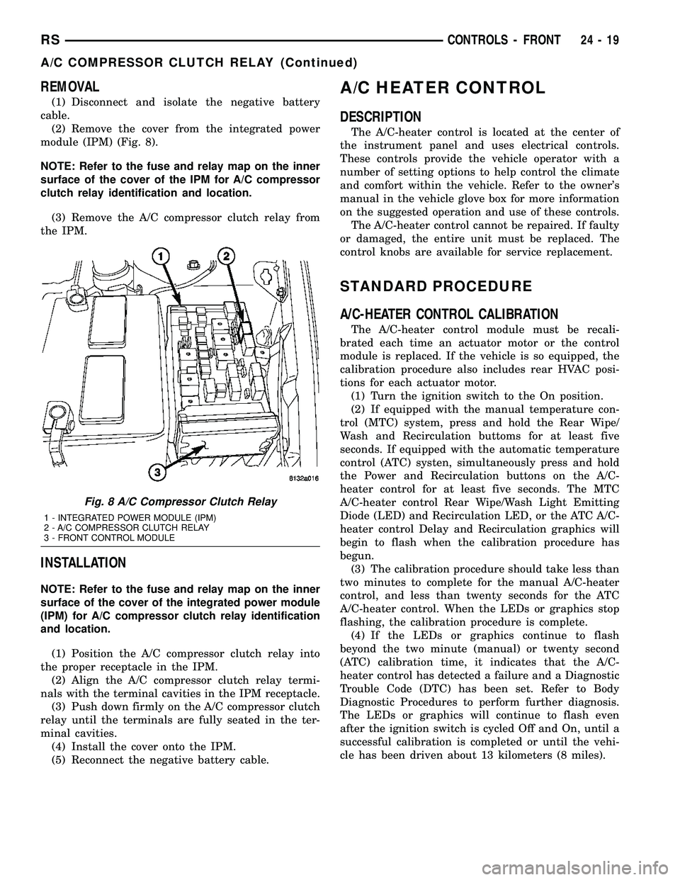
(2) Remove the cover from the integrated power
module (IPM) (Fig. 8).
NOTE: Refer to the fuse and relay map on the inner
surface of the cover of the IPM for A/C compressor
clutch relay identification and location.
(3) Remove the A/C compressor clutch relay from
the IPM.
INSTALLATION
NOTE: Refer to the fuse and relay map on the inner
surface of the cover of the integrated power module
(IPM) for A/C compressor clutch relay identification
and location.
(1) Position the A/C compressor clutch relay into
the proper receptacle in the IPM.
(2) Align the A/C compressor clutch relay termi-
nals with the terminal cavities in the IPM receptacle.
(3) Push down firmly on the A/C compressor clutch
relay until the terminals are fully seated in the ter-
minal cavities.
(4) Install the cover onto the IPM.
(5) Reconnect the negative battery cable.
A/C HEATER CONTROL
DESCRIPTION
The A/C-heater control is located at the center of
the instrument panel and uses electrical controls.
These controls provide the vehicle operator with a
number of setting options to help control the climate
and comfort within the vehicle. Refer to the owner's
manual in the vehicle glove box for more information
on the suggested operation and use of these controls.
The A/C-heater control cannot be repaired. If faulty
or damaged, the entire unit must be replaced. The
control knobs are available for service replacement.
STANDARD PROCEDURE
A/C-HEATER CONTROL CALIBRATION
The A/C-heater control module must be recali-
brated each time an actuator motor or the control
module is replaced. If the vehicle is so equipped, the
calibration procedure also includes rear HVAC posi-
tions for each actuator motor.
(1) Turn the ignition switch to the On position.
(2) If equipped with the manual temperature con-
trol (MTC) system, press and hold the Rear Wipe/
Wash and Recirculation buttoms for at least five
seconds. If equipped with the automatic temperature
control (ATC) systen, simultaneously press and hold
the Power and Recirculation buttons on the A/C-
heater control for at least five seconds. The MTC
A/C-heater control Rear Wipe/Wash Light Emitting
Diode (LED) and Recirculation LED, or the ATC A/C-
heater control Delay and Recirculation graphics will
begin to flash when the calibration procedure has
begun.
(3) The calibration procedure should take less than
two minutes to complete for the manual A/C-heater
control, and less than twenty seconds for the ATC
A/C-heater control. When the LEDs or graphics stop
flashing, the calibration procedure is complete.
(4) If the LEDs or graphics continue to flash
beyond the two minute (manual) or twenty second
(ATC) calibration time, it indicates that the A/C-
heater control has detected a failure and a Diagnostic
Trouble Code (DTC) has been set. Refer to Body
Diagnostic Procedures to perform further diagnosis.
The LEDs or graphics will continue to flash even
after the ignition switch is cycled Off and On, until a
successful calibration is completed or until the vehi-
cle has been driven about 13 kilometers (8 miles).
Fig. 8 A/C Compressor Clutch Relay
1 - INTEGRATED POWER MODULE (IPM)
2 - A/C COMPRESSOR CLUTCH RELAY
3 - FRONT CONTROL MODULE
RSCONTROLS - FRONT24-19
A/C COMPRESSOR CLUTCH RELAY (Continued)
Page 2175 of 2339
The blower motor relay terminals are connected to
the vehicle electrical system through a receptacle in
the Integrated Power Module (IPM). The inputs and
outputs of the blower motor relay include:
²The common feed terminal (30) receives a bat-
tery current input from the battery through a B(+)
circuit at all times.
²The coil ground terminal (85) receives a ground
input through the front/rear blower motor relay con-
trol circuit only when the FCM electronically pulls
the control circuit to ground.
²The coil battery terminal (86) receives a battery
current input from the battery through a B(+) circuit
at all times.
²The normally open terminal (87) provides a bat-
tery current output to the blower motor resistor
(manual heater-A/C control) or blower power module
(automatic heater-A/C control) through a fuse in the
IPM on the fused front blower motor relay output cir-
cuit only when the blower motor relay coil is ener-
gized.
²The normally closed terminal (87A) is not con-
nected to any circuit in this application, but provides
a battery current output only when the blower motor
relay coil is de-energized.
Refer to the appropriate wiring information for
diagnosis and testing of the micro-relay and for com-
plete HVAC wiring diagrams.
REMOVAL
(1) Disconnect and isolate the negative battery
cable.
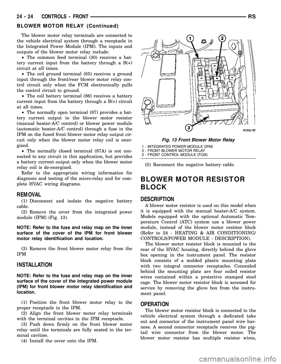
(2) Remove the cover from the integrated power
module (IPM) (Fig. 13).
NOTE: Refer to the fuse and relay map on the inner
surface of the cover of the IPM for front blower
motor relay identification and location.
(3) Remove the front blower motor relay from the
IPM
INSTALLATION
NOTE: Refer to the fuse and relay map on the inner
surface of the cover of the integrated power module
(IPM) for front blower motor relay identification and
location.
(1) Position the front blower motor relay to the
proper receptacle in the IPM.
(2) Align the front blower motor relay terminals
with the terminal cavities in the IPM receptacle.
(3) Push down firmly on the front blower motor
relay until the terminals are fully seated in the ter-
minal cavities.
(4) Install the cover onto the IPM.(5) Reconnect the negative battery cable.
BLOWER MOTOR RESISTOR
BLOCK
DESCRIPTION
A blower motor resistor is used on this model when
it is equipped with the manual heater-A/C system.
Models equipped with the optional Automatic Tem-
perature Control (ATC) system use a blower power
module, instead of the blower motor resistor block
(Refer to 24 - HEATING & AIR CONDITIONING/
CONTROLS/POWER MODULE - DESCRIPTION).
The blower motor resistor block is mounted to the
rear of the HVAC housing, directly behind the glove
box opening in the instrument panel. The resistor
block consists of a molded plastic mounting plate
with two integral connector receptacles. Concealed
behind the mounting plate are four coiled resistor
wires contained within a protective stamped steel
cage. The blower motor resistor block is accessed for
service by removing the glove box from the instru-
ment panel.
OPERATION
The blower motor resistor block is connected to the
vehicle electrical system through a dedicated take
out and connector of the instrument panel wire har-
ness. A second connector receptacle receives the pig-
tail wire connector from the blower motor. The
blower motor resistor has multiple resistor wires,
Fig. 13 Front Blower Motor Relay
1 - INTEGRATED POWER MODULE (IPM)
2 - FRONT BLOWER MOTOR RELAY
2 - FRONT CONTROL MODULE (FCM)
24 - 24 CONTROLS - FRONTRS
BLOWER MOTOR RELAY (Continued)
Page 2316 of 2339
FRONT WIPER/WASHER SWITCH -DIAGNOSIS AND TESTING ..............8R-2
FRONT-WHEEL-DRIVE - INSTALLATION ....2-36
FRONT-WHEEL-DRIVE - REMOVAL ........2-36
FUEL CORRECTION OR ADAPTIVE MEMORIES, OPERATION ...............14-24
FUEL DELIVERY SYSTEM - DIAGNOSIS AND TESTING ........................ 14-2
FUEL DOSING PUMP - DESCRIPTION ....24-117
FUEL DOSING PUMP - INSTALLATION . . . 24-117
FUEL DOSING PUMP - OPERATION .....24-117
FUEL DOSING PUMP - REMOVAL .......24-117
FUEL ENGINE OIL - DESCRIPTION, FLEXIBLE .............................0-3
FUEL FILL DOOR - INSTALLATION .......23-52
FUEL FILL DOOR - REMOVAL ...........23-52
FUEL FILL DOOR BLOCKER LATCH - INSTALLATION ....................... 23-53
FUEL FILL DOOR BLOCKER LATCH - REMOVAL .......................... 23-53
FUEL FILL DOOR BLOCKER LATCH STRIKER - INSTALLATION ..............23-53
FUEL FILL DOOR BLOCKER LATCH STRIKER - REMOVAL .................23-53
FUEL FILL DOOR BLOCKER LOCKOUT LINK - INSTALLATION .................23-54
FUEL FILL DOOR BLOCKER LOCKOUT LINK - REMOVAL ..................... 23-54
FUEL FILLER CAP - DESCRIPTION .......25-13
FUEL FILLER CAP - OPERATION .........25-13
FUEL INJECTOR - DESCRIPTION .........14-30
FUEL INJECTOR - OPERATION ..........14-31
FUEL LEVEL SENDING UNIT / SENSOR - DESCRIPTION ........................ 14-5
FUEL LEVEL SENDING UNIT / SENSOR - INSTALLATION ........................ 14-6
FUEL LEVEL SENDING UNIT / SENSOR - OPERATION .......................... 14-5
FUEL LEVEL SENDING UNIT / SENSOR - REMOVAL ........................... 14-5
FUEL LINES/HOSES AND CLAMPS - DESCRIPTION ........................ 14-7
FUEL PRESSURE GAUGE - STANDARD PROCEDURE ......................... 14-3
FUEL PRESSURE REGULATOR - INSTALLATION ........................ 14-7
FUEL PRESSURE REGULATOR - OPERATION .......................... 14-7
FUEL PRESSURE REGULATOR - REMOVAL ........................... 14-7
FUEL PUMP - DESCRIPTION .............14-8
FUEL PUMP - OPERATION ..............14-8
FUEL PUMP MODULE - DESCRIPTION .....14-8
FUEL PUMP MODULE - OPERATION .......14-9
FUEL PUMP RELAY - DESCRIPTION ......14-32
FUEL PUMP RELAY - OPERATION ........14-32
FUEL REQUIREMENTS - DESCRIPTION ......0-4
FUEL REQUIREMENTS - DIESEL ENGINE - DESCRIPTION ........................0-6
FUEL, SPECIAL TOOLS ............14-27,14-4
FUEL SYSTEM PRESSURE RELEASE PROCEDURE - STANDARD
PROCEDURE ......................... 14-2
FUEL SYSTEM PRESSURE, SPECIFICATIONS ...................... 14-4
FUEL TANK - DESCRIPTION ............14-12
FUEL TANK - OPERATION ..............14-12
FUEL TANK - STANDARD PROCEDURE, DRAINING ........................... 14-2
FUEL TANK FILLER TUBE - INSTALLATION ....................... 14-17
FUEL TANK FILLER TUBE - REMOVAL ....14-16
FULL OPEN SWITCH - DESCRIPTION ....8N-11,
8N-52
FUNCTIONS - DESCRIPTION, CIRCUIT . . 8W-01-6
FUSE - DESCRIPTION, IOD ...........8W-97-3
FUSE - OPERATION, IOD .............8W-97-3
FUSES POWERING SEVERAL LOADS - STANDARD PROCEDURE, TESTING
FOR A SHORT TO GROUND ON ......8W-01-10
FWD - FOLD-IN-FLOOR SEATING - INSTALLATION ........................ 2-45
FWD - FOLD-IN-FLOOR SEATING - REMOVAL ........................... 2-45
FWD - INSTALLATION ..................2-45
FWD - INSTALLATION, REAR WHEEL SPEED SENSOR ....................... 5-93
FWD - INSTALLATION, SPRING ...........2-42FWD - REMOVAL
...................... 2-45
FWD - REMOVAL, REAR WHEEL SPEED SENSOR ............................ 5-93
FWD - REMOVAL, SPRING ..............2-40
GALLERY PLUGS - STANDARD PROCEDURE, ENGINE CORE AND OIL . 9-10,9-88
GAP AND FLUSH MEASUREMENTS - SPECIFICATIONS .................... 23-177
GAP, SPECIFICATIONS - WHEEL SPEED SENSOR AIR ......................... 5-91
GAS STRUT - SECOND ROW - FOLD-IN-FLOOR - INSTALLATION, SEAT . . 23-139
GAS STRUT - SECOND ROW - FOLD-IN-FLOOR - REMOVAL, SEAT ......23-138
GASKET - DIAGNOSIS AND TESTING, CYLINDER HEAD ................. 9-102,9-25
GASKET SURFACE PREPARATION - STANDARD PROCEDURE, ENGINE ....9-11,9-87
GASKETS AND SEALERS, STANDARD PROCEDURE - FORM-IN-PLACE ......9-11,9-86
GAUGE - STANDARD PROCEDURE, FUEL PRESSURE .......................... 14-3
GEAR - DESCRIPTION .................19-26
GEAR - INSTALLATION, LHD ............19-31
GEAR - INSTALLATION, RHD ............19-33
GEAR & LINK ROD - DESCRIPTION, LIFT . 8N-16
GEAR & LINK ROD - INSTALLATION, LIFT ............................... 8N-17
GEAR & LINK ROD - OPERATION, LIFT . . . 8N-16
GEAR & LINK ROD - REMOVAL, LIFT .....8N-16
GEAR - OPERATION .................... 19-26
GEAR - REMOVAL, LHD ...............19-26
GEAR - REMOVAL, RHD ...............19-29
GEAR SHIFT CABLE - INSTALLATION ....21-234
GEAR SHIFT CABLE - REMOVAL . . . 21-233,21-84
GEAR, SPECIAL TOOLS - POWER STEERING .......................... 19-34
GEARSHIFT CABLE ADJUSTMENT, ADJUSTMENTS ..................... 21-235
GEARTRAIN - DESCRIPTION, PLANETARY .................. 21-112,21-263
GEARTRAIN - OPERATION, PLANETARY . 21-112, 21-263
GENERAL - WARNINGS .............8W-01-7
GENERAL DIAGNOSIS - DIAGNOSIS AND TESTING, 4XTE TRANSAXLE .......21-149,21-5
GENERATOR - DESCRIPTION ...........8F-24
GENERATOR - OPERATION .............8F-24
GENERATOR DECOUPLER PULLEY - DESCRIPTION ....................... 8F-28
GENERATOR DECOUPLER PULLEY - DIAGNOSIS AND TESTING ..............8F-28
GENERATOR DECOUPLER PULLEY - INSTALLATION ....................... 8F-29
GENERATOR DECOUPLER PULLEY - OPERATION ......................... 8F-28
GENERATOR DECOUPLER PULLEY - REMOVAL .......................... 8F-29
GENERATOR, SPECIFICATIONS ..........8F-23
GLASS - DESCRIPTION, HEATED .........8G-1
GLASS - INSTALLATION, DOOR .........23-17
GLASS - INSTALLATION, LIFTGATE ......23-164
GLASS - INSTALLATION, SLIDING DOOR . 23-163
GLASS - OPERATION, HEATED ...........8G-2
GLASS - REMOVAL, DOOR .............23-16
GLASS - REMOVAL, LIFTGATE .........23-164
GLASS - REMOVAL, SLIDING DOOR .....23-163
GLASS INTEGRAL ANTENNA - EXPORT - DESCRIPTION, QUARTER ..............8A-13
GLASS INTEGRAL ANTENNA - EXPORT - OPERATION, QUARTER ................8A-13
GLASS INTEGRAL ANTENNA, EXPORT - QUARTER .......................... 8A-13
GLASS PANEL - INSTALLATION ........23-173
GLASS PANEL - REMOVAL ............23-173
GLASS PANEL ADJUSTMENT, ADJUSTMENTS - SUNROOF ...........23-173
GLASS RUN WEATHERSTRIP - INSTALLATION, FRONT DOOR ..........23-166
GLASS RUN WEATHERSTRIP - REMOVAL, FRONT DOOR .............23-166
GLASS-OUTSIDE REARVIEW MIRROR - INSTALLATION ....................... 23-61
GLASS-OUTSIDE REARVIEW MIRROR - REMOVAL .......................... 23-61
GLOVE BOX - INSTALLATION ...........23-66
GLOVE BOX - REMOVAL ...............23-66GLOVE BOX LAMP SWITCH -
INSTALLATION ....................... 8L-22
GLOVE BOX LAMP SWITCH - REMOVAL . . 8L-22
GLOVE BOX LATCH - INSTALLATION .....23-66
GLOVE BOX LATCH - REMOVAL .........23-66
GLOVE BOX LATCH STRIKER - INSTALLATION ....................... 23-66
GLOVE BOX LATCH STRIKER - REMOVAL . 23-66
GRID REPAIR PROCEDURE, STANDARD PROCEDURE ......................... 8G-5
GRILLE - DESCRIPTION ...............23-55
GRILLE - INSTALLATION ...............23-55
GRILLE - INSTALLATION, COWL .........23-50
GRILLE - REMOVAL ..................23-55
GRILLE - REMOVAL, COWL ............23-50
GROCERY BAG RETAINER - INSTALLATION, PLASTIC ..............23-149
GROCERY BAG RETAINER - REMOVAL, PLASTIC .......................... 23-149
GROMMET REPLACEMENT, STANDARD PROCEDURE - PUSH-PIN ..............8N-48
GROUND - OPERATION, PCM ...........8E-14
GROUND - STANDARD PROCEDURE, TESTING FOR A SHORT TO ..........8W-01-9
GROUND AND SPLICE INFORMATION - DESCRIPTION, CONNECTOR ..........8W-01-7
GROUND ON FUSES POWERING SEVERAL LOADS - STANDARD
PROCEDURE, TESTING FOR A SHORT
TO.............................8W -01-10
GUIDE - INSTALLATION, UNDER SEAT STORAGE BIN ...................... 23-150
GUIDE - REMOVAL, UNDER SEAT STORAGE BIN ...................... 23-150
GUIDE PIN BUSHINGS (CONTINENTAL TEVES BRAKES) - ASSEMBLY, CALIPER ....5-25
GUIDE PIN BUSHINGS (CONTINENTAL TEVES BRAKES) - DISASSEMBLY,
CALIPER ............................ 5-24
GUIDE PINS (TRW BRAKES) - INSTALLATION, DISC BRAKE CALIPER .....5-32
GUIDE PINS (TRW BRAKES) - REMOVAL, DISC BRAKE CALIPER .................. 5-31
HALF SHAFT - DIAGNOSIS AND TESTING . . . 3-1
HALF SHAFT - FRONT - DESCRIPTION ......3-1
HALF SHAFT - FRONT - INSTALLATION .....3-4
HALF SHAFT - FRONT - REMOVAL .........3-2
HALF SHAFT - FRONT - SPECIFICATIONS ....3-6
HANDLE - INSTALLATION, ASSIST .......23-79
HANDLE - INSTALLATION, EXTERIOR ....23-22,
23-40
HANDLE - INSTALLATION, INSIDE LATCH . . 23-34
HANDLE - INSTALLATION, OUTSIDE ......23-36
HANDLE - INSTALLATION, RECLINER ....23-108
HANDLE - REMOVAL, ASSIST ...........23-79
HANDLE - REMOVAL, EXTERIOR . . . 23-21,23-40
HANDLE - REMOVAL, INSIDE LATCH .....23-34
HANDLE - REMOVAL, OUTSIDE .........23-35
HANDLE - REMOVAL, RECLINER .......23-108
HANDLE ACTUATOR - INSTALLATION, INSIDE ............................. 23-27
HANDLE ACTUATOR - REMOVAL, INSIDE . . 23-27
HANDLE CABLE - INSTALLATION, INSIDE . . 23-38
HANDLE CABLE - INSTALLATION, OUTSIDE ........................... 23-37
HANDLE CABLE - REMOVAL, INSIDE .....23-37
HANDLE CABLE - REMOVAL, OUTSIDE ....23-37
HANDLE SWITCH - DESCRIPTION, EXTERIOR .......................... 8N-10
HANDLE SWITCH - INSTALLATION, EXTERIOR .......................... 8N-10
HANDLE SWITCH - OPERATION, EXTERIOR .......................... 8N-10
HANDLE SWITCH - REMOVAL, EXTERIOR . 8N-10
HANDLING AIRBAGS - STANDARD PROCEDURE ......................... 8O-6
HANDLING TUBING AND FITTINGS, STANDARD PROCEDURE ...............24-69
HANDS FREE MODULE - INSTALLATION ....8T-3
HANDS FREE MODULE - REMOVAL .......8T-3
HARNESS - DESCRIPTION, WIRING ......8N-59
HARNESS - DIAGNOSIS AND TESTING, WIRING ..........................8W -01-7
HARNESS - INSTALLATION, WIRING .....8N-59
HARNESS - OPERATION, WIRING ........8N-59
HARNESS - REMOVAL, WIRING .........8N-59
HCU (HYDRAULIC CONTROL UNIT) - DESCRIPTION ....................... 5-100
RS INDEX15
Description Group-Page Description Group-Page Description Group-Page
Page 2319 of 2339
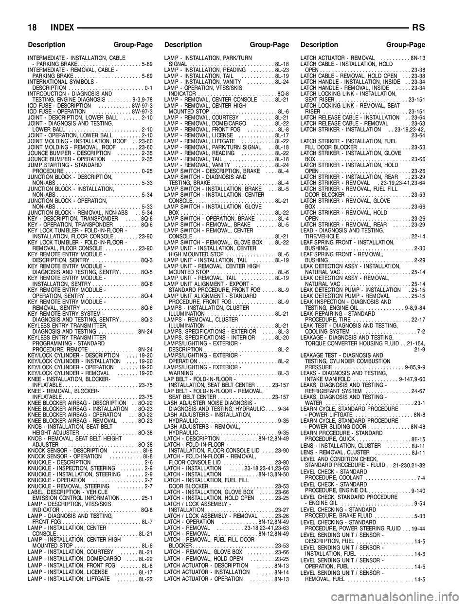
INTERMEDIATE - INSTALLATION, CABLE- PARKING BRAKE ..................... 5-69
INTERMEDIATE - REMOVAL, CABLE - PARKING BRAKE ...................... 5-69
INTERNATIONAL SYMBOLS - DESCRIPTION .........................0-1
INTRODUCTION - DIAGNOSIS AND TESTING, ENGINE DIAGNOSIS ........9-3,9-78
IOD FUSE - DESCRIPTION ...........8W-97-3
IOD FUSE - OPERATION .............8W-97-3
JOINT - DESCRIPTION, LOWER BALL ......2-10
JOINT - DIAGNOSIS AND TESTING, LOWER BALL ........................ 2-10
JOINT - OPERATION, LOWER BALL .......2-10
JOINT MOLDING - INSTALLATION, ROOF . . 23-60
JOINT MOLDING - REMOVAL, ROOF ......23-60
JOUNCE BUMPER - DESCRIPTION ........2-35
JOUNCE BUMPER - OPERATION ..........2-35
JUMP STARTING - STANDARD PROCEDURE ......................... 0-25
JUNCTION BLOCK - DESCRIPTION, NON-ABS ............................ 5-33
JUNCTION BLOCK - INSTALLATION, NON-ABS ............................ 5-34
JUNCTION BLOCK - OPERATION, NON-ABS ............................ 5-33
JUNCTION BLOCK - REMOVAL, NON-ABS . . 5-34
KEY - DESCRIPTION, TRANSPONDER .....8Q-6
KEY - OPERATION, TRANSPONDER .......8Q-6
KEY LOCK TUMBLER - FOLD-IN-FLOOR - INSTALLATION, FLOOR CONSOLE ........23-90
KEY LOCK TUMBLER - FOLD-IN-FLOOR - REMOVAL, FLOOR CONSOLE ...........23-90
KEY REMOTE ENTRY MODULE - DESCRIPTION, SENTRY ................8Q-3
KEY REMOTE ENTRY MODULE - DIAGNOSIS AND TESTING, SENTRY .......8Q-5
KEY REMOTE ENTRY MODULE - INSTALLATION, SENTRY ................8Q-6
KEY REMOTE ENTRY MODULE - OPERATION, SENTRY .................. 8Q-4
KEY REMOTE ENTRY MODULE - REMOVAL, SENTRY ................... 8Q-6
KEY REMOTE ENTRY SYSTEM - DIAGNOSIS AND TESTING, SENTRY .......8Q-3
KEYLESS ENTRY TRANSMITTER, DIAGNOSIS AND TESTING .............8N-24
KEYLESS ENTRY TRANSMITTER PROGRAMMING - STANDARD
PROCEDURE, REMOTE ................8N-24
KEY/LOCK CYLINDER - DESCRIPTION ....19-20
KEY/LOCK CYLINDER - INSTALLATION ....19-20
KEY/LOCK CYLINDER - OPERATION ......19-20
KEY/LOCK CYLINDER - REMOVAL .......19-20
KNEE - INSTALLATION, BLOCKER- INFLATABLE ......................... 23-75
KNEE - REMOVAL, BLOCKER- INFLATABLE ......................... 23-75
KNEE BLOCKER AIRBAG - DESCRIPTION . . 8O-22
KNEE BLOCKER AIRBAG - INSTALLATION . 8O-23
KNEE BLOCKER AIRBAG - OPERATION . . . 8O-22
KNEE BLOCKER AIRBAG - REMOVAL .....8O-23
KNOB - INSTALLATION, SEAT BELT HEIGHT ADJUSTER ................... 8O-38
KNOB - REMOVAL, SEAT BELT HEIGHT ADJUSTER ......................... 8O-38
KNOCK SENSOR - DESCRIPTION ..........8I-8
KNOCK SENSOR - OPERATION ...........8I-8
KNUCKLE - DESCRIPTION ................2-6
KNUCKLE - INSPECTION, STEERING ........2-9
KNUCKLE - INSTALLATION, STEERING ......2-9
KNUCKLE - OPERATION .................2-7
KNUCKLE - REMOVAL, STEERING .........2-7
LABEL, DESCRIPTION - VEHICLE EMISSION CONTROL INFORMATION .......25-1
LAMP - DESCRIPTION, VTSS/SKIS INDICATOR .......................... 8Q-8
LAMP - DIAGNOSIS AND TESTING, FRONT FOG .......................... 8L-7
LAMP - INSTALLATION, CENTER CONSOLE ........................... 8L-21
LAMP - INSTALLATION, CENTER HIGH MOUNTED STOP ...................... 8L-6
LAMP - INSTALLATION, COURTESY ......8L-21
LAMP - INSTALLATION, DOME/CARGO ....8L-22
LAMP - INSTALLATION, FRONT FOG .......8L-8
LAMP - INSTALLATION, LICENSE ........8L-17
LAMP - INSTALLATION, LIFTGATE .......8L-22 LAMP - INSTALLATION, PARK/TURN
SIGNAL ............................ 8L-18
LAMP - INSTALLATION, READING ........8L-23
LAMP - INSTALLATION, TAIL ...........8L-19
LAMP - INSTALLATION, VANITY .........8L-24
LAMP - OPERATION, VTSS/SKIS INDICATOR .......................... 8Q-8
LAMP - REMOVAL, CENTER CONSOLE ....8L-21
LAMP - REMOVAL, CENTER HIGH MOUNTED STOP ...................... 8L-6
LAMP - REMOVAL, COURTESY ..........8L-21
LAMP - REMOVAL, DOME/CARGO .......8L-22
LAMP - REMOVAL, FRONT FOG ..........8L-8
LAMP - REMOVAL, LICENSE ............8L-17
LAMP - REMOVAL, LIFTGATE ...........8L-22
LAMP - REMOVAL, PARK/TURN SIGNAL . . 8L-18
LAMP - REMOVAL, READING ...........8L-22
LAMP - REMOVAL, TAIL ...............8L-18
LAMP - REMOVAL, VANITY .............8L-24
LAMP SWITCH - DESCRIPTION, BRAKE ....8L-4
LAMP SWITCH - DIAGNOSIS AND TESTING, BRAKE ...................... 8L-4
LAMP SWITCH - INSTALLATION, BRAKE . . . 8L-5
LAMP SWITCH - INSTALLATION, CENTER CONSOLE ........................... 8L-21
LAMP SWITCH - INSTALLATION, GLOVE BOX ............................... 8L-22
LAMP SWITCH - OPERATION, BRAKE ......8L-4
LAMP SWITCH - REMOVAL, BRAKE .......8L-5
LAMP SWITCH - REMOVAL, CENTER CONSOLE ........................... 8L-21
LAMP SWITCH - REMOVAL, GLOVE BOX . . 8L-22
LAMP UNIT - INSTALLATION, CENTER HIGH MOUNTED STOP .................8L-6
LAMP UNIT - INSTALLATION, TAIL .......8L-19
LAMP UNIT - REMOVAL, CENTER HIGH MOUNTED STOP ...................... 8L-6
LAMP UNIT - REMOVAL, TAIL ...........8L-19
LAMP UNIT ALIGNMENT - EXPORT - STANDARD PROCEDURE, FRONT FOG .....8L-9
LAMP UNIT ALIGNMENT - STANDARD PROCEDURE, FRONT FOG ...............8L-9
LAMPS - INSTALLATION, CLUSTER ILLUMINATION ...................... 8L-21
LAMPS - REMOVAL, CLUSTER ILLUMINATION ...................... 8L-21
LAMPS, SPECIFICATIONS - EXTERIOR .....8L-3
LAMPS, SPECIFICATIONS - INTERIOR ....8L-20
LAMPS/LIGHTING - EXTERIOR - DESCRIPTION ........................ 8L-2
LAMPS/LIGHTING - EXTERIOR - OPERATION .......................... 8L-2
LAMPS/LIGHTING - EXTERIOR - WARNING ........................... 8L-3
LAP BELT - FOLD-IN-FLOOR - INSTALLATION, SEAT BELT CENTER .....23-157
LAP BELT - FOLD-IN-FLOOR - REMOVAL, SEAT BELT CENTER .................. 23-157
LASH ADJUSTER NOISE DIAGNOSIS - DIAGNOSIS AND TESTING, HYDRAULIC ....9-34
LASH ADJUSTERS - INSTALLATION, HYDRAULIC .......................... 9-35
LASH ADJUSTERS - REMOVAL, HYDRAULIC .......................... 9-35
LATCH - DESCRIPTION ...........8N-12,8N-49
LATCH - FOLD-IN-FLOOR - INSTALLATION, FLOOR CONSOLE LID ....23-90
LATCH - FOLD-IN-FLOOR - REMOVAL, FLOOR CONSOLE LID .................23-90
LATCH - INSTALLATION .....23-18,23-41,23-63
LATCH - INSTALLATION ..........8N-13,8N-50
LATCH - INSTALLATION, FUEL FILL DOOR BLOCKER ..................... 23-53
LATCH - INSTALLATION, GLOVE BOX .....23-66
LATCH - INSTALLATION, HOLD OPEN .....23-25
LATCH / LOCK ASSEMBLY - INSTALLATION ....................... 23-27
LATCH / LOCK ASSEMBLY - REMOVAL ....23-26
LATCH - OPERATION ............8N-12,8N-49
LATCH - REMOVAL .........23-18,23-41,23-63
LATCH - REMOVAL ..............8N-12,8N-49
LATCH - REMOVAL, FUEL FILL DOOR BLOCKER ........................... 23-53
LATCH - REMOVAL, GLOVE BOX .........23-66
LATCH - REMOVAL, HOLD OPEN ........23-25
LATCH ACTUATOR - DESCRIPTION ......8N-13
LATCH ACTUATOR - INSTALLATION ......8N-14
LATCH ACTUATOR - OPERATION ........8N-13 LATCH ACTUATOR - REMOVAL
..........8N-13
LATCH CABLE - INSTALLATION, HOLD OPEN .............................. 23-38
LATCH CABLE - REMOVAL, HOLD OPEN . . . 23-38
LATCH HANDLE - INSTALLATION, INSIDE . . 23-34
LATCH HANDLE - REMOVAL, INSIDE .....23-34
LATCH LOCKING LINK - INSTALLATION, SEAT RISER ........................ 23-151
LATCH LOCKING LINK - REMOVAL, SEAT RISER ............................ 23-151
LATCH RELEASE CABLE - INSTALLATION . . 23-64
LATCH RELEASE CABLE - REMOVAL .....23-63
LATCH STRIKER - INSTALLATION . . 23-19,23-42, 23-64
LATCH STRIKER - INSTALLATION, FUEL FILL DOOR BLOCKER .................23-53
LATCH STRIKER - INSTALLATION, GLOVE BOX ............................... 23-66
LATCH STRIKER - INSTALLATION, HOLD OPEN .............................. 23-26
LATCH STRIKER - INSTALLATION, REAR . . 23-29
LATCH STRIKER - REMOVAL . 23-19,23-41,23-64
LATCH STRIKER - REMOVAL, FUEL FILL DOOR BLOCKER ..................... 23-53
LATCH STRIKER - REMOVAL, GLOVE BOX ............................... 23-66
LATCH STRIKER - REMOVAL, HOLD OPEN .............................. 23-26
LATCH STRIKER - REMOVAL, REAR ......23-29
LEAD - DIAGNOSIS AND TESTING, TIRE/VEHICLE ......................... 22-14
LEAF SPRING FRONT - INSTALLATION, BUSHING ............................ 2-30
LEAF SPRING FRONT - REMOVAL, BUSHING ............................ 2-29
LEAK DETECTION ASSY - INSTALLATION, NATURAL VAC ....................... 25-14
LEAK DETECTION ASSY - REMOVAL, NATURAL VAC ....................... 25-14
LEAK DETECTION PUMP - INSTALLATION . 25-15
LEAK DETECTION PUMP - REMOVAL .....25-15
LEAK INSPECTION - DIAGNOSIS AND TESTING, ENGINE OIL ...............9-8,9-84
LEAK REPAIRING - STANDARD PROCEDURE, TIRE ................... 22-17
LEAK TEST - DIAGNOSIS AND TESTING, COOLING SYSTEM .....................7-2
LEAKAGE - DIAGNOSIS AND TESTING, TORQUE CONVERTER HOUSING FLUID . . 21-154, 21-9
LEAKAGE TEST - DIAGNOSIS AND TESTING, CYLINDER COMBUSTION
PRESSURE ....................... 9-85,9-9
LEAKS - DIAGNOSIS AND TESTING, INTAKE MANIFOLD ...............9-147,9-60
LEAKS, DIAGNOSIS AND TESTING - REFRIGERANT SYSTEM ...............24-67
LEAKS, DIAGNOSIS AND TESTING - WATER ............................. 23-1
LEARN CYCLE, STANDARD PROCEDURE - POWER LIFTGATE ................... 8N-8
LEARN CYCLE, STANDARD PROCEDURE - POWER SLIDING DOOR ..............8N-48
LEARN PROCEDURE - STANDARD PROCEDURE, QUICK .................. 8E-15
LENS - INSTALLATION, CLUSTER ........8J-11
LENS - REMOVAL, CLUSTER ............8J-11
LEVEL AND CONDITION CHECK, STANDARD PROCEDURE - FLUID . . 21-230,21-82
LEVEL CHECK - STANDARD PROCEDURE, COOLANT .................7-4
LEVEL CHECK - STANDARD PROCEDURE, ENGINE OIL ..............9-140
LEVEL CHECK, STANDARD PROCEDURE - ENGINE OIL ........................ 9-54
LEVEL CHECKING - STANDARD PROCEDURE, BRAKE FLUID .............5-33
LEVEL CHECKING - STANDARD PROCEDURE, POWER STEERING FLUID . . . 19-44
LEVEL SENDING UNIT / SENSOR - DESCRIPTION, FUEL ................... 14-5
LEVEL SENDING UNIT / SENSOR - INSTALLATION, FUEL .................. 14-6
LEVEL SENDING UNIT / SENSOR - OPERATION, FUEL ..................... 14-5
LEVEL SENDING UNIT / SENSOR - REMOVAL, FUEL ...................... 14-5
18 INDEXRS
Description Group-Page Description Group-Page Description Group-Page