Stop and stall CHRYSLER VOYAGER 2020 Owners Manual
[x] Cancel search | Manufacturer: CHRYSLER, Model Year: 2020, Model line: VOYAGER, Model: CHRYSLER VOYAGER 2020Pages: 516, PDF Size: 28.69 MB
Page 2 of 516

WARNING: Operating, servicing and maintaining a passenger vehicle or off-highway motor vehicle can
expose you to chemicals including engine exhaust, carbon monoxide, phthalates, and lead, which are known to the
State of California to cause cancer and birth defects or other reproductive harm. To minimize exposure, avoid
breathing exhaust, do not idle the engine except as necessary, service your vehicle in a well-ventilated area and
wear gloves or wash your hands frequently when servicing your vehicle. For more information go to
www.P65Warnings.ca.gov/passenger-vehicle.
This Owner’s Manual illustrates and describes the operation of features and equipment that are either standard or optional on this vehicle. This manual may also include a
description of features and equipment that are no longer available or were not ordered on this vehicle. Please disregard any features and equipment described in this manual
that are not on this vehicle. FCA US LLC reserves the right to make changes in design and specifications, and/or make additions to or improvements to its products without
imposing any obligation upon itself to install them on products previously manufactured.
With respect to any vehicles sold in Canada, the name FCA US LLC shall be deemed to be deleted and the name FCA Canada Inc.
used in substitution therefore.
If you are the first registered retail owner of your vehicle, you may obtain a complimentary printed copy of the Warranty Booklet by calling 1-800-247-9753 (U.S.)
or 1-800 -387-1143 (Canada) or by contacting your dealer.
This Owner’s Manual is intended to familiarize you with the important features of your vehicle. Your most up-to-date Owner’s Manual, Navigation/ Uconnect manuals and
Warranty Booklet can be found by visiting the website on the back cover. U.S. residents can purchase replacement kits by visiting www.techauthority.com and Canadian
residents can purchase replacement kits by calling 1-800 -387-1143.
The driver’s primary responsibility is the safe operation of the vehicle. Driving while distracted can result in loss of vehicle control, resulting in an accident and personal
injury. FCA US LLC strongly recommends that the driver use extreme caution when using any device or feature that may take their attention off the road. Use of any
electrical devices, such as cellular telephones, computers, portable radios, vehicle navigation or other devices, by the driver while the vehicle is moving is dangerous and
could lead to a serious accident. Texting while driving is also dangerous and should never be done while the vehicle is moving. If you find yourself unable to devote your
full attention to vehicle operation, pull off the road to a safe location and stop your vehicle. Some states or provinces prohibit the use of cellular telephones or texting
while driving. It is always the driver’s responsibility to comply with all local laws.
This Owner’s Manual has been prepared to help you get acquainted with your new Chrysler brand vehicle and to provide a convenient reference source
for common questions.
Not all features shown in this manual may apply to your vehicle. For additional information, visit www.mopar.com (U.S.), www.mopar.ca (Canada) or your
local Chrysler brand dealer.
Drunk driving is one of the most frequent causes of accidents. Your driving ability can be seriously impaired with blood
alcohol levels far below the legal minimum. If you are drinking, don’t drive. Ride with a designated non-drinking driver,
call a cab, a friend or use public transportation.
DRIVING AND ALCOHOL
Driving after drinking can lead to an accident. Your perceptions are less sharp, your reflexes are slower and your judgment
is impaired when you have been drinking. Never drink and then drive.
WARNING!
Page 15 of 516
GETTING TO KNOW YOUR VEHICLE13
Features/Benefits
Pre-installed on your Uconnect touchscreen radio
Enhanced search and browsing capability
Robust NAV application (if equipped)
Add selected topics to a fast-access Favor -
ites category
Icon and symbol glossary
Warranty information
Crucial driver information and assistance:
Operating Instructions
Warranty Information
Fluid Level Standards
Maintenance Schedules
Emergency Procedures
911 Contact and More
TIP:
When viewing a topic, tap the star icon to add it
to your Favorites, for easy access in the future.
KEYS
Key Fob
Your vehicle uses a keyless ignition system. The
ignition system consists of a key fob with
Remote Keyless Entry (RKE) and a START/STOP
push button ignition system. The RKE system
uses a receiver module in the vehicle that
wirelessly links with the key fob.
NOTE:
The key fob may not be found if it is located next
to a mobile phone, laptop or other electronic
device; these devices may block the key fob’s
wireless signal.
This system allows you to lock or unlock the
doors and liftgate, activate the Panic Alarm,
optional power liftgate, left power sliding door,
and right power sliding door from distances up
to approximately 66 ft (20 m) using a key fob.
When any button on the key fob is pushed, or when any signal is being transferred between
the key fob and the vehicle, an LED light on the
key fob will flash as an indicator. The key fob
does not need to be pointed at the vehicle to
activate the system.
NOTE:
The emergency key allows for entry into the
vehicle should the battery in the vehicle or the
key fob become depleted. The emergency key is
also for locking/unlocking the glove compart
-
ment. You can keep the emergency key with you
when valet parking.
2
20_RU_OM_EN_US_t.book Page 13
Page 58 of 516
56GETTING TO KNOW YOUR VEHICLE
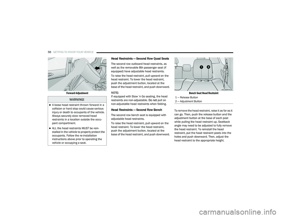
Forward Adjustment
Head Restraints — Second Row Quad Seats
The second row outboard head restraints, as
well as the removable 8th passenger seat (if
equipped) have adjustable head restraints.
To raise the head restraint, pull upward on the
head restraint. To lower the head restraint,
push the adjustment button, located at the
base of the head restraint, and push downward.
NOTE:
If equipped with Stow ‘n Go seating, the head
restraints are non-adjustable. Do not pull on
non-adjustable head restraints when folding.
Head Restraints — Second Row Bench
The second row bench seat is equipped with
adjustable head restraints.
To raise the head restraint, pull upward on the
head restraint. To lower the head restraint,
push the adjustment button, located at the
base of the head restraint, and push downward.
Bench Seat Head Restraint
To remove the head restraint, raise it as far as it
can go. Then, push the release button and the
adjustment button at the base of each post
while pulling the head restraint up. Seatback
angle may need to be adjusted to fully remove
the head restraint. To reinstall the head
restraint, put the head restraint posts into the
holes and push downward. Then, adjust the
head restraint to the appropriate height.
WARNING!
A loose head restraint thrown forward in a
collision or hard stop could cause serious
injury or death to occupants of the vehicle.
Always securely stow removed head
restraints in a location outside the occu -
pant compartment.
ALL the head restraints MUST be rein -
stalled in the vehicle to properly protect the
occupants. Follow the re-installation
instructions above prior to operating the
vehicle or occupying a seat.
1 — Release Button
2 — Adjustment Button
20_RU_OM_EN_US_t.book Page 56
Page 59 of 516
GETTING TO KNOW YOUR VEHICLE57
NOTE:
For child restraint tethering, refer to “Occupant
Restraint Systems” in “Safety” for further infor -
mation.
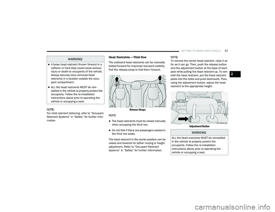
Head Restraints — Third Row
The outboard head restraints can be manually
folded forward for improved rearward visibility.
Pull the release strap to fold them forward.
Release Straps
NOTE:
The head restraints must be raised manually
when occupying the third row.
Do not fold if there are passengers seated in
the third row seats.
The head restraint in the center position can be
raised and lowered for tether routing or height
adjustment. Refer to “Occupant Restraint
Systems” in “Safety” for further information. NOTE:
To remove the center head restraint, raise it as
far as it can go. Then, push the release button
and the adjustment button at the base of each
post while pulling the head restraint up. To rein
-
stall the head restraint, put the head restraint
posts into the holes and push downward. Then,
using the adjustment button, adjust the head
restraint to the appropriate height.
Adjustment Button
WARNING!
A loose head restraint thrown forward in a
collision or hard stop could cause serious
injury or death to occupants of the vehicle.
Always securely stow removed head
restraints in a location outside the occu -
pant compartment.
ALL the head restraints MUST be rein -
stalled in the vehicle to properly protect the
occupants. Follow the re-installation
instructions above prior to operating the
vehicle or occupying a seat.
WARNING!
ALL the head restraints MUST be reinstalled
in the vehicle to properly protect the
occupants. Follow the re-installation
instructions above prior to operating the
vehicle or occupying a seat.
2
20_RU_OM_EN_US_t.book Page 57
Page 109 of 516
GETTING TO KNOW YOUR VEHICLE107
5. When finished, push power button to turn
vacuum off and store vacuum hose and any
attachments.
6. Before exiting the vehicle:
If the ignition is in the ACC position, push
the START/STOP ignition button to place
ignition in the OFF position, remove key
fob from the vehicle, and lock the vehicle.
If the engine is running, raise all of the
windows, push the START/STOP ignition
button to place ignition in the OFF posi -tion, remove key fob from the vehicle,
close all of the doors and the liftgate and
lock the vehicle.
Vacuum Troubleshooting
DO NOT use with any opening blocked. If an
object becomes lodged in the hose, attempt
to fully extend the hose in a straight line while
the vacuum motor is running. If this does not
dislodge the object, turn the vacuum OFF and
remove the hose from the vehicle following
the removal instructions below. If the filter is
clogged, follow the emptying debris bin
procedure and lightly tap the filter on the
collection bin to remove any collected debris
from the filter. Both the bin and the filter can
be rinsed with water if needed. To avoid mold
and stale odors, allow both to dry completely
before reinstalling in your vehicle. If the filter
has tears, holes or other damage and needs
to be replaced, please contact an authorized
dealer.
If there are any other issues with your
vacuum, contact an authorized dealer. Your
vacuum has no user serviceable parts. Debris Bin
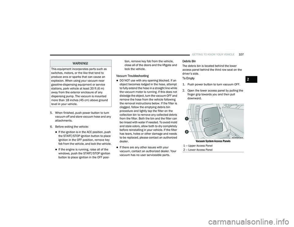
The debris bin is located behind the lower
access panel behind the third row seat on the
driver’s side.
To Empty
1. Push power button to turn vacuum OFF.
2. Open the lower access panel by pulling the
finger grip towards you and then pull
downward.
Vacuum System Access Panels
WARNING!
This equipment incorporates parts such as
switches, motors, or the like that tend to
produce arcs or sparks that can cause an
explosion. When using your vacuum near
gasoline-dispensing equipment or service
stations, park vehicle at least 20 ft (6 m)
away from the exterior enclosure of any
dispensing pump. The vacuum is mounted
more than 18 inches (45 cm) above ground
level in your vehicle.
1 — Upper Access Panel
2 — Lower Access Panel
2
20_RU_OM_EN_US_t.book Page 107
Page 141 of 516
GETTING TO KNOW YOUR INSTRUMENT PANEL139
Loss of the battery charge may indicate one or
more of the following conditions:
The charging system cannot deliver enough
electrical power to the vehicle system
because the electrical loads are larger than
the capability of charging system. The
charging system is still functioning properly.
Turning on all possible vehicle electrical
loads (e.g. HVAC to max settings, exterior and
interior lights, overloaded power outlets +12
Volts, 150W, USB ports) during certain
driving conditions (city driving, towing,
frequent stopping).
Installing options like additional lights,
upfitter electrical accessories, audio
systems, alarms and similar devices.
Unusual driving cycles (short trips separated
by long parking periods).
The vehicle was parked for an extended
period of time (weeks, months).
The battery was recently replaced and was
not charged completely.
The battery was discharged by an electrical
load left on when the vehicle was parked.
The battery was used for an extended period
with the engine not running to supply radio,
lights, chargers, +12 Volt portable appli-
ances like vacuum cleaners, game consoles
and similar devices.
What to do when an electrical load reduction
action message is present (“Battery Saver On”
or “Battery Saver Mode”)
During a trip:
Reduce power to unnecessary loads if
possible:
Turn off redundant lights (interior or exte -
rior)
Check what may be plugged in to power
outlets +12 Volts, 150W, USB ports
Check HVAC settings (blower, tempera -
ture)
Check the audio settings (volume) After a trip:
Check if any aftermarket equipment was
installed (additional lights, upfitter electrical
accessories, audio systems, alarms) and
review specifications if any (load and Ignition
Off Draw currents).
Evaluate the latest driving cycles (distance,
driving time and parking time).
The vehicle should have service performed if
the message is still present during consecu
-
tive trips and the evaluation of the vehicle
and driving pattern did not help to identify the
cause.
Instrument Cluster Display Programmable
Features Screen Setup
Push the up or down arrow button to scroll
through the Menu Items until the Screen Setup
displays in the instrument cluster display. Push
the OK button to enter Screen Setup. The
Screen Setup feature allows you to change what
information is displayed in the instrument
cluster display as well as the location that
information is displayed.
3
20_RU_OM_EN_US_t.book Page 139
Page 144 of 516
142GETTING TO KNOW YOUR INSTRUMENT PANEL
Vehicles equipped with the Anti-Lock Brake
System (ABS) are also equipped with Electronic
Brake Force Distribution (EBD). In the event of
an EBD failure, the Brake Warning Light will turn
on along with the ABS Light. Immediate repair to
the ABS system is required.
Operation of the Brake Warning Light can be
checked by turning the ignition switch from the
OFF position to the ON/RUN position. The light
should illuminate for approximately two
seconds. The light should then turn off unless
the parking brake is applied or a brake fault is
detected. If the light does not illuminate, have
the light inspected by an authorized dealer.
The light also will turn on when the parking
brake is applied with the ignition switch in the
ON/RUN position.
NOTE:
This light shows only that the parking brake is
applied. It does not show the degree of brake
application.Door Open Warning Light — If Equipped
This warning light will illuminate when
a door is ajar/open and not fully
closed. This indicator will reflect
which doors are open.
NOTE:
If the vehicle is moving, there will also be a
single chime.
Electric Power Steering Fault Warning Light
This warning light will turn on when
there's a fault with the Electric Power
Steering (EPS) system. Refer to
“Power Steering” in “Starting And
Operating” for further information.
Electronic Throttle Control (ETC) Warning
Light
This warning light will illuminate to
indicate a problem with the Electronic
Throttle Control (ETC) system. If a
problem is detected while the vehicle
is running, the light will either stay on or flash
depending on the nature of the problem. Cycle
the ignition when the vehicle is safely and
completely stopped and the transmission is
placed in the PARK (P) position. The light should
turn off. If the light remains on with the vehicle
running, your vehicle will usually be drivable;
however, see an authorized dealer for service
as soon as possible.
NOTE:
This light may turn on if the accelerator and
brake pedals are pressed at the same time.
If the light continues to flash when the vehicle is
running, immediate service is required and you
may experience reduced performance, an
elevated/rough idle, or engine stall and your
vehicle may require towing. The light will come
on when the ignition is placed in the ON/RUN or
WARNING!
Continued operation with reduced assist
could pose a safety risk to yourself and
others. Service should be obtained as soon
as possible
20_RU_OM_EN_US_t.book Page 142
Page 149 of 516
GETTING TO KNOW YOUR INSTRUMENT PANEL147
indicated on the vehicle placard or tire inflation
pressure label, you should determine the
proper tire inflation pressure for those tires.
As an added safety feature, your vehicle has
been equipped with a Tire Pressure Monitoring
System (TPMS) that illuminates a low tire
pressure telltale when one or more of your tires is
significantly under-inflated. Accordingly, when
the low tire pressure telltale illuminates, you
should stop and check your tires as soon as
possible, and inflate them to the proper pressure.
Driving on a significantly under-inflated tire
causes the tire to overheat and can lead to tire
failure. Under-inflation also reduces fuel
efficiency and tire tread life, and may affect the
vehicle’s handling and stopping ability.
Please note that the TPMS is not a substitute for
proper tire maintenance, and it is the driver’s
responsibility to maintain correct tire pressure,
even if under-inflation has not reached the level
to trigger illumination of the TPMS low tire
pressure telltale.
Your vehicle has also been equipped with a TPMS
malfunction indicator to indicate when the
system is not operating properly. The TPMS
malfunction indicator is combined with the low
tire pressure telltale. When the system detects a
malfunction, the telltale will flash for
approximately one minute and then remain
continuously illuminated. This sequence will
continue upon subsequent vehicle start-ups as
long as the malfunction exists. When the
malfunction indicator is illuminated, the system
may not be able to detect or signal low tire
pressure as intended. TPMS malfunctions may
occur for a variety of reasons, including the
installation of replacement or alternate tires or
wheels on the vehicle that prevent the TPMS from
functioning properly. Always check the TPMS
malfunction telltale after replacing one or more
tires or wheels on your vehicle to ensure that the
replacement or alternate tires and wheels allow
the TPMS to continue to function properly.
Yellow Indicator Lights
Forward Collision Warning Off Indicator Light
— If Equipped
This indicator light illuminates to
indicate that Forward Collision
Warning is off.
CAUTION!
The TPMS has been optimized for the original
equipment tires and wheels. TPMS pressures
and warning have been established for the tire
size equipped on your vehicle. Undesirable
system operation or sensor damage may result
when using replacement equipment that is not
of the same size, type, and/or style.
Aftermarket wheels can cause sensor damage.
Using aftermarket tire sealants may cause the
Tire Pressure Monitoring System (TPMS)
sensor to become inoperable. After using an
aftermarket tire sealant it is recommended
that you take your vehicle to an authorized
dealer to have your sensor function checked.
3
20_RU_OM_EN_US_t.book Page 147
Page 154 of 516
152 (Continued)
SAFETY
SAFETY FEATURES
Anti-Lock Brake System (ABS)
The Anti-Lock Brake System (ABS) provides
increased vehicle stability and brake
performance under most braking conditions.
The system automatically prevents wheel lock,
and enhances vehicle control during braking.
The ABS performs a self-check cycle to ensure
that the ABS is working properly each time the
vehicle is started and driven. During this
self-check, you may hear a slight clicking sound
as well as some related motor noises.
ABS is activated during braking when the
system detects one or more wheels begin to
lock. Road conditions such as ice, snow, gravel,
bumps, railroad tracks, loose debris, or panic
stops may increase the likelihood of ABS
activation(s).You also may experience the following when
ABS activates:
The ABS motor noise (it may continue to run
for a short time after the stop)
The clicking sound of solenoid valves
Brake pedal pulsations
A slight drop of the brake pedal at the end of
the stop
NOTE:
These are all normal characteristics of ABS.
WARNING!
The ABS contains sophisticated electronic
equipment that may be susceptible to inter -
ference caused by improperly installed or
high output radio transmitting equipment.
This interference can cause possible loss of
anti-lock braking capability. Installation of
such equipment should be performed by
qualified professionals.
Pumping of the Anti-Lock Brakes will
diminish their effectiveness and may lead
to a collision. Pumping makes the stopping
distance longer. Just press firmly on your
brake pedal when you need to slow down or
stop.
The ABS cannot prevent the natural laws of
physics from acting on the vehicle, nor can
it increase braking or steering efficiency
beyond that afforded by the condition of the
vehicle brakes and tires or the traction
afforded.
The ABS cannot prevent collisions,
including those resulting from excessive
speed in turns, following another vehicle
too closely, or hydroplaning.
The capabilities of an ABS equipped vehicle
must never be exploited in a reckless or
dangerous manner that could jeopardize
the user’s safety or the safety of others.
WARNING! (Continued)
20_RU_OM_EN_US_t.book Page 152
Page 170 of 516
168SAFETY
(Continued)
to rise to approximately 28 psi (193 kPa), but
the TPMS Warning Light will still be on. In this
situation, the TPMS Warning Light will turn off
only after the tires are inflated to the vehicle’s
recommended cold placard pressure value.
NOTE:
When filling warm tires, the tire pressure may
need to be increased up to an additional 4 psi
(28 kPa) above the recommended cold placard
pressure in order to turn the TPMS Warning
Light off. NOTE:
The TPMS is not intended to replace normal
tire care and maintenance, or to provide
warning of a tire failure or condition.
The TPMS should not be used as a tire pres-
sure gauge while adjusting your tire pressure.
Driving on a significantly underinflated tire
causes the tire to overheat and can lead to
tire failure. Underinflation also reduces fuel
efficiency and tire tread life, and may affect
the vehicle’s handling and stopping ability.
The TPMS is not a substitute for proper tire
maintenance, and it is the driver’s responsi -
bility to maintain correct tire pressure using
an accurate tire pressure gauge, even if
underinflation has not reached the level to
trigger illumination of the TPMS Warning
Light.
Seasonal temperature changes will affect
tire pressure, and the TPMS will monitor the
actual tire pressure in the tire.CAUTION!
The TPMS has been optimized for the orig -
inal equipment tires and wheels. TPMS pres -
sures and warning have been established for
the tire size equipped on your vehicle. Unde -
sirable system operation or sensor damage
may result when using replacement equip -
ment that is not of the same size, type, and/
or style. The TPM sensor is not designed for
use on aftermarket wheels and may
contribute to a poor overall system perfor -
mance or sensor damage. Customers are
encouraged to use OEM wheels to assure
proper TPM feature operation.
Using aftermarket tire sealants may cause
the Tire Pressure Monitoring System
(TPMS) sensor to become inoperable. After
using an aftermarket tire sealant it is
recommended that you take your vehicle to
an authorized dealer to have your sensor
function checked.
After inspecting or adjusting the tire pres -
sure always reinstall the valve stem cap.
This will prevent moisture and dirt from
entering the valve stem, which could
damage the TPMS sensor.
CAUTION! (Continued)
20_RU_OM_EN_US_t.book Page 168