engine CHRYSLER VOYAGER 2020 User Guide
[x] Cancel search | Manufacturer: CHRYSLER, Model Year: 2020, Model line: VOYAGER, Model: CHRYSLER VOYAGER 2020Pages: 516, PDF Size: 28.69 MB
Page 24 of 516
22GETTING TO KNOW YOUR VEHICLE
General Information
The following regulatory statement applies to all
Radio Frequency (RF) devices equipped in this
vehicle:
This device complies with Part 15 of the FCC
Rules and with Innovation, Science and
Economic Development Canada license-exempt
RSS standard(s). Operation is subject to the
following two conditions:
1. This device may not cause harmful
interference, and
2. This device must accept any interference received, including interference that may
cause undesired operation.
Le présent appareil est conforme aux CNR
d`Innovation, Science and Economic
Development applicables aux appareils radio
exempts de licence. L'exploitation est autorisée
aux deux conditions suivantes:
1. l'appareil ne doit pas produire de brouillage, et
2. l'utilisateur de l'appareil doit accepter tout brouillage radioélectrique subi, même si le brouillage est susceptible d'en compro
-
mettre le fonctionnement.
La operación de este equipo está sujeta a las
siguientes dos condiciones:
1. es posible que este equipo o dispositivo no cause interferencia perjudicial y
2. este equipo o dispositivo debe aceptar cualquier interferencia, incluyendo la que
pueda causar su operación no deseada.
NOTE:
Changes or modifications not expressly
approved by the party responsible for compli -
ance could void the user’s authority to operate
the equipment.
SENTRY KEY
The Sentry Key Immobilizer system prevents
unauthorized vehicle operation by disabling the
engine. The system does not need to be armed
or activated. Operation is automatic, regardless
of whether the vehicle is locked or unlocked. The system uses a key fob, keyless push button
ignition and a Radio Frequency (RF) receiver to
prevent unauthorized vehicle operation.
Therefore, only key fobs that are programmed
to the vehicle can be used to start and operate
the vehicle. The system cannot reprogram a key
fob obtained from another vehicle.
After placing the ignition switch in the ON/RUN
position, the vehicle security light will turn on for
three seconds for a bulb check. If the light
remains on after the bulb check, it indicates
that there is a problem with the electronics. In
addition, if the light begins to flash after the
bulb check, it indicates that someone
attempted to start the engine with an invalid key
fob. In the event that a valid key fob is used to
start the engine but there is an issue with the
vehicle electronics, the engine will start and
shut off after two seconds.
If the vehicle security light turns on during
normal vehicle operation (vehicle running for
longer than 10 seconds), it indicates that there
is a fault in the electronics. Should this occur,
have the vehicle serviced as soon as possible by
an authorized dealer.
20_RU_OM_EN_US_t.book Page 22
Page 26 of 516
24GETTING TO KNOW YOUR VEHICLE
VEHICLE SECURITY ALARM — IF EQUIPPED
The vehicle security alarm monitors the vehicle
doors for unauthorized entry and the ignition
switch for unauthorized operation. When the
alarm is activated, the interior switches for door
locks, power sliding doors and power liftgate
are disabled. The vehicle security alarm
provides both audible and visible signals. If
something triggers the alarm, the vehicle
security alarm will provide the following audible
and visible signals: the horn will pulse, the park
lamps and/or turn signals will flash, and the
vehicle security light in the instrument cluster
will flash.
To Arm The System
Follow these steps to arm the vehicle security
alarm:
1. Make sure the vehicle’s ignition is placed
in the OFF position. Refer to "Starting The
Engine" in "Starting And Operating" for
further information.
For vehicles equipped with Keyless
Enter-N-Go — Passive Entry, make sure
the vehicle ignition system is OFF. 2. Perform one of the following methods to
lock the vehicle:
Push lock on the interior power door lock
switch with the driver and/or passenger
door open.
Push the lock button on the exterior
Passive Entry Door Handle with a valid
key fob available in the same exterior
zone. Refer to "Keyless Enter-N-Go —
Passive Entry" in “Doors” in this chapter
for further information.
Push the lock button on the key fob.
3. If any doors are open, close them.
To Disarm The System
The vehicle security alarm can be disarmed
using any of the following methods:
Push the unlock button on the key fob.
Grasp the Passive Entry Unlock Door Handle
(if equipped). Refer to "Keyless Enter-N-Go —
Passive Entry" in “Doors” in this chapter for
further information.
Hands Free Liftgate Passive Entry activation
(if equipped).
Cycle the vehicle ignition system out of the
OFF position.
For vehicles equipped with Keyless
Enter-N-Go — Passive Entry, push the
keyless ignition START/STOP ignition
button (requires at least one valid key fob
in the vehicle).
NOTE:
The driver's door key cylinder and the liftgate
button on the key fob cannot arm or disarm
the vehicle security alarm.
The vehicle security alarm remains armed
during power liftgate entry. Pushing the lift -
gate button will not disarm the vehicle secu -
rity alarm. If someone enters the vehicle
through the liftgate and opens any door, the
alarm will sound.
When the vehicle security alarm is armed,
the interior power door lock switches will not
unlock the doors.
20_RU_OM_EN_US_t.book Page 24
Page 36 of 516
34GETTING TO KNOW YOUR VEHICLE
DRIVER MEMORY SETTINGS — IF EQUIPPED
This feature allows the driver to save up to two
different memory profiles for easy recall
through a memory switch. Each memory profile
saves desired position settings for the following
features:
Driver’s seat
Easy Entry/Exit seat operation (on/off) (if
equipped)
Power steering wheel position (if equipped)
Side mirrors (if equipped)
A set of desired radio station presets
NOTE:
Your vehicle is equipped with two key fobs, each
can be linked to either memory position 1 or 2.
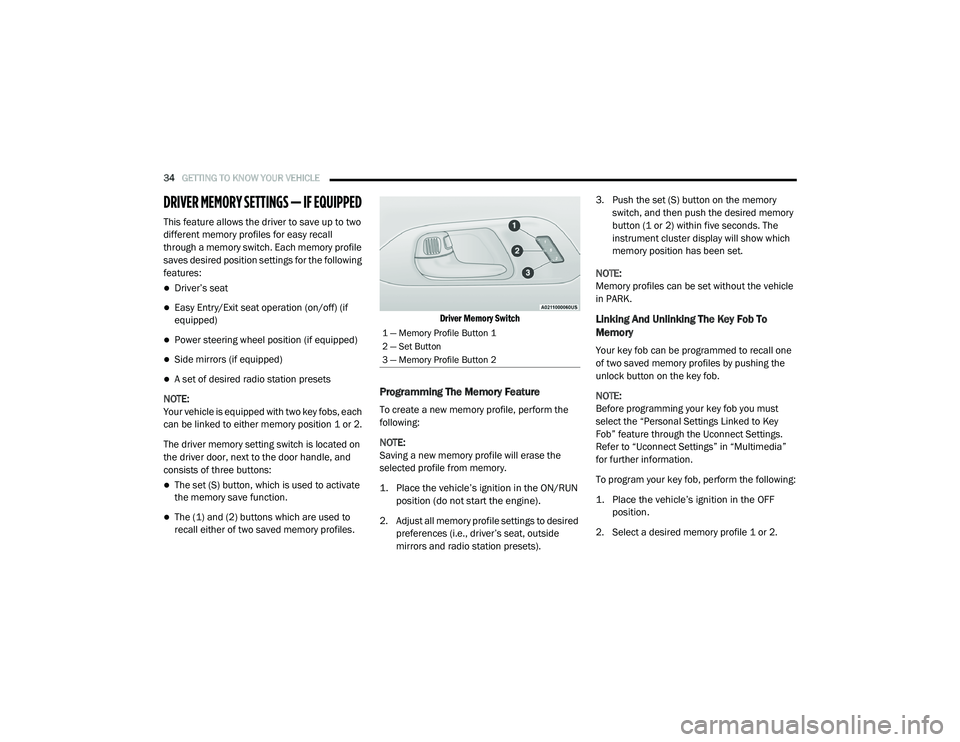
The driver memory setting switch is located on
the driver door, next to the door handle, and
consists of three buttons:
The set (S) button, which is used to activate
the memory save function.
The (1) and (2) buttons which are used to
recall either of two saved memory profiles.
Driver Memory Switch
Programming The Memory Feature
To create a new memory profile, perform the
following:
NOTE:
Saving a new memory profile will erase the
selected profile from memory.
1. Place the vehicle’s ignition in the ON/RUN
position (do not start the engine).
2. Adjust all memory profile settings to desired preferences (i.e., driver’s seat, outside
mirrors and radio station presets). 3. Push the set (S) button on the memory
switch, and then push the desired memory
button (1 or 2) within five seconds. The
instrument cluster display will show which
memory position has been set.
NOTE:
Memory profiles can be set without the vehicle
in PARK.
Linking And Unlinking The Key Fob To
Memory
Your key fob can be programmed to recall one
of two saved memory profiles by pushing the
unlock button on the key fob.
NOTE:
Before programming your key fob you must
select the “Personal Settings Linked to Key
Fob” feature through the Uconnect Settings.
Refer to “Uconnect Settings” in “Multimedia”
for further information.
To program your key fob, perform the following:
1. Place the vehicle’s ignition in the OFF position.
2. Select a desired memory profile 1 or 2.
1 — Memory Profile Button 1
2 — Set Button
3 — Memory Profile Button 2
20_RU_OM_EN_US_t.book Page 34
Page 55 of 516
GETTING TO KNOW YOUR VEHICLE53
Heated Seats
Front Heated Seats — If Equipped
The front heated seats control buttons are
located within the climate or controls screen of
the touchscreen.
You can choose from HI, LO or off heat settings.
The indicator lights in each switch indicate the
level of heat in use. Two indicator lights will
illuminate for HI, one for LO and none for off.
Press the heated seat button once to turn
the HI setting on.
Press the heated seat button a second
time to turn the LO setting on.
Press the heated seat button a third time
to turn the heating elements off.
The level of heat selected will stay on until the
operator changes it.
NOTE:
Once a heat setting is selected, heat will be
felt within two to five minutes.
The engine must be running for the heated
seats to operate. Vehicles Equipped With Remote Start
On models that are equipped with remote start,
the heated seats can be programmed to come
on during a remote start.
This feature can be programmed through the
Uconnect system. Refer to “Uconnect Settings”
in “Multimedia” for further information.
Rear Heated Seats — If Equipped
On some models, the second row seats are
equipped with heaters. There are two heated
seat switches that allow the second row
passengers to operate the seats independently.
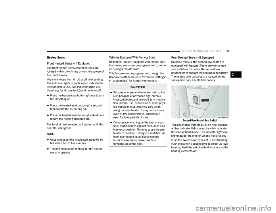
The heated seat switches are located on the
sliding side door handle trim panels.
Second Row Heated Seat Switch
You can choose from HI, LO or off heat settings.
Amber indicator lights in each switch indicate
the level of heat in use. Two indicator lights will
illuminate for HI, one for LO and none for off.
Push the switch once to select HI-level heating.
Push the switch a second time to select LO-level
heating. Push the switch a third time to shut the
heating elements off.
WARNING!
Persons who are unable to feel pain to the
skin because of advanced age, chronic
illness, diabetes, spinal cord injury, medica -
tion, alcohol use, exhaustion or other phys -
ical condition must exercise care when
using the seat heater. It may cause burns
even at low temperatures, especially if
used for long periods of time.
Do not place anything on the seat or seat -
back that insulates against heat, such as a
blanket or cushion. This may cause the seat
heater to overheat. Sitting in a seat that has
been overheated could cause serious
burns due to the increased surface
temperature of the seat.
2
20_RU_OM_EN_US_t.book Page 53
Page 56 of 516
54GETTING TO KNOW YOUR VEHICLE
NOTE:
Once a heat setting is selected, heat will be felt
within two to five minutes.
When the HI-level setting is selected, the heater
will provide a boosted heat level during the initial
stages of operation. Then, the heat output will
drop to the normal HI-level. The level of heat
selected will stay on until the operator changes it.
Ventilated Seats — If Equipped
Located in the first row seat cushions are small
fans that draw the air from the passenger
compartment and move air through fine
perforations in the seat cover to help keep the
driver and front passenger cooler in higher
ambient temperatures. The fans operate at two
speeds, HI and LO.
The front ventilated seats control buttons are
located within the climate or controls screen of
the touchscreen.
Press the ventilated seat button once to
choose HI.
Press the ventilated seat button a second
time to choose LO.
Press the ventilated seat button a third
time to turn the ventilated seat off.
NOTE:
The engine must be running for the ventilated
seats to operate.
Vehicles Equipped With Remote Start
On models that are equipped with remote start,
the ventilated seats can be programmed to
come on during a remote start.
This feature can be programmed through the
Uconnect system. Refer to “Uconnect Settings”
in “Multimedia” for further information.
Adjustable Armrest (Front Seats) — If
Equipped
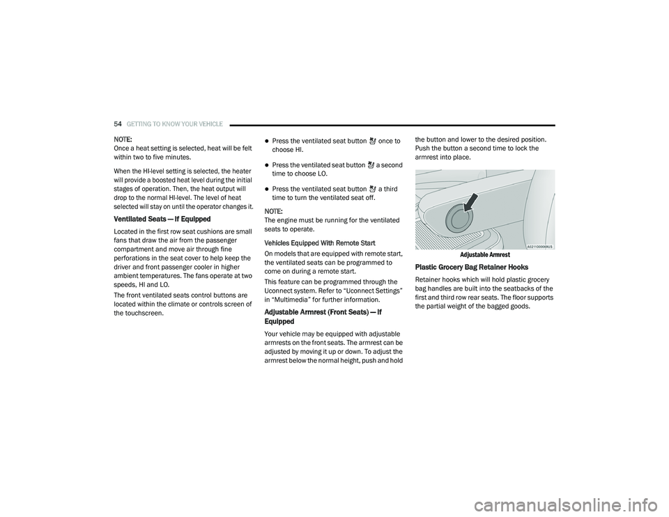
Your vehicle may be equipped with adjustable
armrests on the front seats. The armrest can be
adjusted by moving it up or down. To adjust the
armrest below the normal height, push and hold the button and lower to the desired position.
Push the button a second time to lock the
armrest into place.
Adjustable Armrest
Plastic Grocery Bag Retainer Hooks
Retainer hooks which will hold plastic grocery
bag handles are built into the seatbacks of the
first and third row rear seats. The floor supports
the partial weight of the bagged goods.
20_RU_OM_EN_US_t.book Page 54
Page 61 of 516
GETTING TO KNOW YOUR VEHICLE59
The heated steering wheel control button is
located within the Uconnect system. You can
gain access to the control button through the
climate screen or the controls screen.
Press the heated steering wheel button
once to turn the heating element on.
Press the heated steering wheel button a
second time to turn the heating element off.
NOTE:
The engine must be running for the heated
steering wheel to operate.
Vehicles Equipped With Remote Start
On models that are equipped with remote start,
the heated steering wheel can be programmed
to come on during a remote start through the
Uconnect system. Refer to “Uconnect Settings”
in “Multimedia” for further information.
MIRRORS
Inside Day/Night Mirror — If Equipped
A single ball joint mirror is used to allow the
driver to adjust up, down and left, right. Mirror
should be adjusted to center on the view
through the rear window.
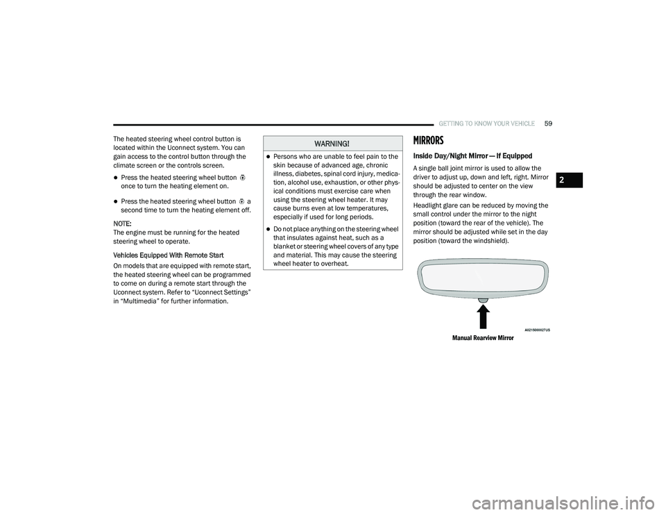
Headlight glare can be reduced by moving the
small control under the mirror to the night
position (toward the rear of the vehicle). The
mirror should be adjusted while set in the day
position (toward the windshield).
Manual Rearview Mirror
WARNING!
Persons who are unable to feel pain to the
skin because of advanced age, chronic
illness, diabetes, spinal cord injury, medica -
tion, alcohol use, exhaustion, or other phys -
ical conditions must exercise care when
using the steering wheel heater. It may
cause burns even at low temperatures,
especially if used for long periods.
Do not place anything on the steering wheel
that insulates against heat, such as a
blanket or steering wheel covers of any type
and material. This may cause the steering
wheel heater to overheat.
2
20_RU_OM_EN_US_t.book Page 59
Page 65 of 516
GETTING TO KNOW YOUR VEHICLE63
EXTERIOR LIGHTS
Multifunction Lever
The multifunction lever is located on the left
side of the steering column. The multifunction
lever controls the turn signals, headlight high/
low beams, and flash-to-pass functions.
Multifunction Lever
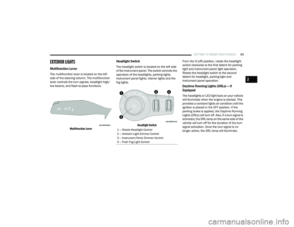
Headlight Switch
The headlight switch is located on the left side
of the instrument panel. The switch controls the
operation of the headlights, parking lights,
instrument panel lights, interior lights and the
fog lights.
Headlight Switch
From the O (off) position, rotate the headlight
switch clockwise to the first detent for parking
light and instrument panel light operation.
Rotate the headlight switch to the second
detent for headlight, parking light and
instrument panel operation.
Daytime Running Lights (DRLs) — If
Equipped
The headlights or LED light bars on your vehicle
will illuminate when the engine is started. This
provides a constant lights on condition until the
ignition is placed in the OFF position. If the
parking brake is applied, the Daytime Running
Lights (DRLs) will turn off. Also, if a turn signal is
activated, the DRL lamp on the same side of the
vehicle will turn off for the duration of the turn
signal activation. Once the turn signal is no
longer active, the DRL lamp will illuminate.
1 — Rotate Headlight Control
2 — Ambient Light Dimmer Control
3 — Instrument Panel Dimmer Control
4 — Push Fog Light Control
2
20_RU_OM_EN_US_t.book Page 63
Page 67 of 516
GETTING TO KNOW YOUR VEHICLE65
NOTE:
The engine must be running before the head -
lights will come on in the Automatic mode.
Headlights On With Wipers — If Equipped
When your headlights are in the AUTO mode
and the engine is running, the headlights will
automatically turn on when the wiper system is
also turned on. Headlights on when windshield
wipers are on may be found on vehicles
equipped with an automatic headlight system.
NOTE:
The Headlights with Wipers feature can be
turned on or off through the Uconnect system.
Refer to “Uconnect Settings” in “Multimedia”
for further information.
Headlight Delay — If Equipped
This feature provides the safety of headlight
illumination for up to 90 seconds after exiting
your vehicle.
To activate the delay feature, place the ignition
in the OFF position while the headlights are still
on. The 90 second delay interval begins when
headlight switch is turned off. If the headlights or parking lights are turned back on or the
ignition is placed in the ON position, the delay
will be cancelled.
When exiting the vehicle the driver can choose
to have the headlights remain on for 30, 60, or
90 seconds or not remain on. To change the
timer setting, select the proper setting through
the Uconnect System.
Refer to “Uconnect Settings” in “Multimedia”
for further information.
If the headlights are turned off before the
ignition, they will turn off in the normal manner.
NOTE:
The headlights must be turned off within
45 seconds of placing the ignition in the OFF
position to activate this feature.Lights-On Reminder
If the headlights or the parking lights are left on
after the ignition switch is placed in the OFF
position, a chime will sound when the driver's
door is opened.
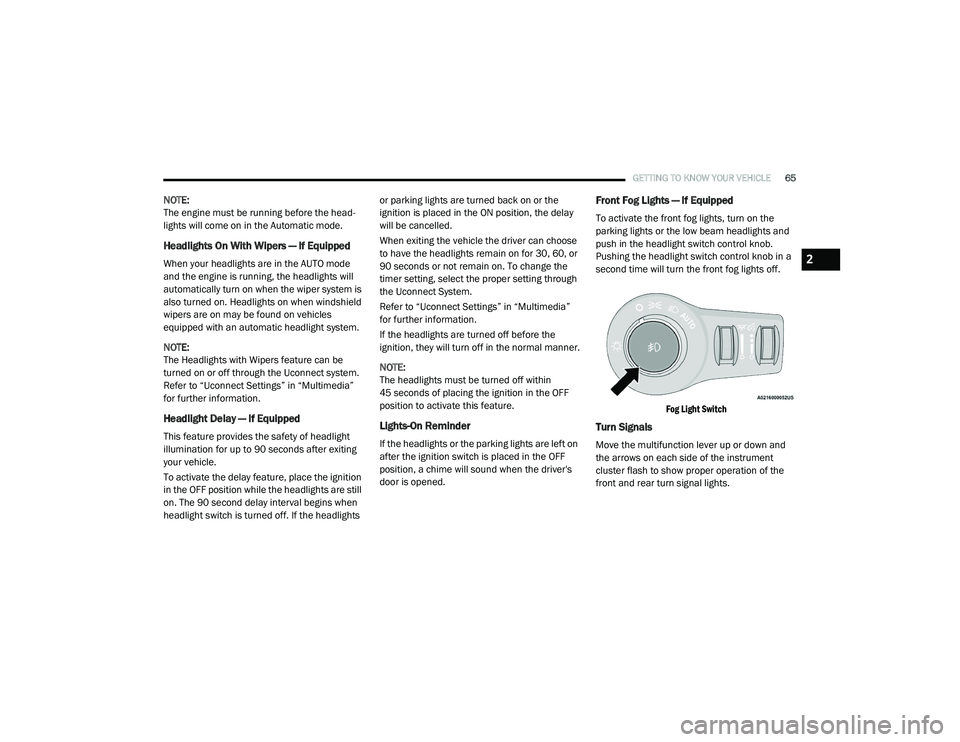
Front Fog Lights — If Equipped
To activate the front fog lights, turn on the
parking lights or the low beam headlights and
push in the headlight switch control knob.
Pushing the headlight switch control knob in a
second time will turn the front fog lights off.
Fog Light Switch
Turn Signals
Move the multifunction lever up or down and
the arrows on each side of the instrument
cluster flash to show proper operation of the
front and rear turn signal lights.
2
20_RU_OM_EN_US_t.book Page 65
Page 93 of 516
GETTING TO KNOW YOUR VEHICLE91
NOTE:
It is not necessary to move the temperature
settings for cold or hot vehicles. The system
automatically adjusts the temperature,
mode, and blower speed to provide comfort
as quickly as possible.
The temperature can be displayed in U.S. or
Metric units by selecting the U.S./Metric
customer-programmable feature. Refer to
the “Uconnect Settings” in “Multimedia” for
further information.
To provide you with maximum comfort in the
Automatic mode during cold start-ups, the
blower fan will remain on low until the engine
warms up. The blower will increase in speed
and transition into Auto mode.
Manual Operation Override
This system offers a full complement of manual
override features. The AUTO symbol in the front
Automatic Temperature Control (ATC) display
will be turned off when the system is being used
in the manual mode.
Operating Tips
NOTE:
Refer to the chart at the end of this section for
suggested control settings for various weather
conditions.
Summer Operation
The engine cooling system must be protected
with a high-quality antifreeze coolant to provide
proper corrosion protection and to protect
against engine overheating. OAT coolant
(conforming to MS.90032) is recommended.
Refer to “Fluids And Lubricants” in “Technical
Specifications” for proper coolant selection.
Winter Operation
To ensure the best possible heater and
defroster performance, make sure the engine
cooling system is functioning properly and the
proper amount, type, and concentration of
coolant is used. Refer to “Fluids And
Lubricants” in “Technical Specifications” for
proper coolant selection. Use of the air
Recirculation mode during Winter months is not
recommended, because it may cause window
fogging.
Vacation/Storage
Before you store your vehicle, or keep it out of
service (i.e., vacation) for two weeks or more,
run the air conditioning system at idle for about
five minutes, in fresh air with the blower setting
on high. This will ensure adequate system
lubrication to minimize the possibility of
compressor damage when the system is started
again.
Window Fogging
Vehicle windows tend to fog on the inside in
mild, rainy, and/or humid weather. To clear the
windows, select Defrost or Mix mode and
increase the front blower speed. Do not use the
Recirculation mode without A/C (air
conditioning) for long periods, as fogging may
occur.
2
20_RU_OM_EN_US_t.book Page 91
Page 100 of 516
98GETTING TO KNOW YOUR VEHICLE
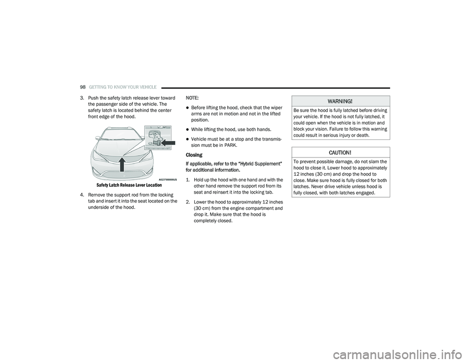
3. Push the safety latch release lever toward
the passenger side of the vehicle. The
safety latch is located behind the center
front edge of the hood.
Safety Latch Release Lever Location
4. Remove the support rod from the locking tab and insert it into the seat located on the
underside of the hood. NOTE:
Before lifting the hood, check that the wiper
arms are not in motion and not in the lifted
position.
While lifting the hood, use both hands.
Vehicle must be at a stop and the transmis
-
sion must be in PARK.
Closing
If applicable, refer to the “Hybrid Supplement”
for additional information.
1. Hold up the hood with one hand and with the
other hand remove the support rod from its
seat and reinsert it into the locking tab.
2. Lower the hood to approximately 12 inches (30 cm) from the engine compartment and
drop it. Make sure that the hood is
completely closed.
WARNING!
Be sure the hood is fully latched before driving
your vehicle. If the hood is not fully latched, it
could open when the vehicle is in motion and
block your vision. Failure to follow this warning
could result in serious injury or death.
CAUTION!
To prevent possible damage, do not slam the
hood to close it. Lower hood to approximately
12 inches (30 cm) and drop the hood to
close. Make sure hood is fully closed for both
latches. Never drive vehicle unless hood is
fully closed, with both latches engaged.
20_RU_OM_EN_US_t.book Page 98