power steering CHRYSLER VOYAGER 2021 User Guide
[x] Cancel search | Manufacturer: CHRYSLER, Model Year: 2021, Model line: VOYAGER, Model: CHRYSLER VOYAGER 2021Pages: 348, PDF Size: 18.73 MB
Page 184 of 348
182MULTIMEDIA
Once Android Auto™ is up and running on your
Uconnect system, the following features can be
utilized using your smartphone’s data plan:
Google Maps™ for navigation
Google Play Music, Spotify, iHeart Radio, etc. for
music
Hands-free calling and texting for communica -
tion
Various compatible apps
Maps
Push and hold the Voice Recognition (VR)
button on the steering wheel until the
beep or tap the Microphone icon to ask
Google to take you to a desired
destination by voice. You can also touch the
Navigation icon in Android Auto™ to access other
navigation apps.
While using Android Auto™, Google Maps™
provides voice-guided:
Navigation
Live traffic information
Lane guidance
For further information, refer to
www.android.com/auto/ (US) or https://
www.android.com/intl/en_ca/auto/ (Canada). For further information on the navigation function,
please refer to
https://support.google.com/
android or https://support.google.com/
androidauto/.
Music
Android Auto™ allows you to access and
stream your favorite music with apps like
YouTube Music, iHeartRadio, and Spotify.
Using your smartphone’s data plan, you
can stream endless music on the road.
NOTE:Music apps, playlists, and stations must be set up
on your smartphone prior to using Android Auto™
for them to work with Android Auto™.
NOTE:To see the track details for the music playing
through Android Auto™, select the Uconnect
system’s media screen.
For further information, refer to
https://
support.google.com/androidauto.
Communication
With Android Auto™ connected, push and
hold the VR button on the steering wheel
to activate voice recognition specific to
Android Auto™. This allows you to send
and reply to text messages, have incoming text
messages read out loud, and place and receive
hands-free calls.
Apps
The Android Auto™ App displays all the compatible
apps that are available to use with Android Auto™,
every time it is launched. You must have the
compatible app downloaded, and you must be
signed in to the app through your mobile device for
it to work with Android Auto™.
Refer to
https://play.google.com/store/apps/ to
see the latest list of available apps for Android
Auto™.
Android Auto™ Voice Command
NOTE:Feature availability depends on your carrier and
mobile phone manufacturer. Some Android Auto™
features may or may not be available in every
region and/or language.
Android Auto™ allows you to use your voice to
interact with Android’s™ best-in-class speech
technology through your vehicle’s voice recognition
system, and use your smartphone’s data plan to
project your Android™-powered smartphone and a
number of its apps onto your Uconnect
touchscreen. Connect your Android™ 6.0 or higher
to one of the media USB ports, using the
factory-provided USB cable, and press the new
Android Auto™ icon that replaces your “Phone”
icon on the main menu bar to begin Android Auto™.
21_RUV_OM_EN_USC_t.book Page 182
Page 187 of 348

MULTIMEDIA185
Push and hold the VR button on the steering wheel,
or press and hold the Home button within Apple
CarPlay®, to activate Siri, which recognizes natural
voice commands to use a list of your iPhone’s®
features:
Phone
Music
Messages
Maps — If Equipped
Additional Apps — If Equipped
NOTE:Apple CarPlay® is a trademark of Apple® Inc.
iPhone® is a trademark of Apple® Inc., registered
in the US and other countries. Apple® terms of use
and privacy statements apply.
ANDROID AUTO™ AND APPLE
C
ARPLAY® TIPS AND TRICKS
Android Auto™ And Apple CarPlay® Automatic
Bluetooth® Pairing
After connecting to Android Auto™ or Apple
CarPlay® for the first time and undergoing the
setup procedure, the smartphone pairs to the
Uconnect system via Bluetooth® without any setup
required every time it is within range, if Bluetooth®
is turned on.
NOTE:Apple CarPlay® uses a USB connection while
Android Auto™ uses both USB and Bluetooth®
connections to function. The connected device is
unavailable to other devices when connected
using Android Auto™ or Apple CarPlay®.
Multiple Devices Connecting To The Uconnect
System — If Equipped
It is possible to have multiple devices connected to
the Uconnect system. For example, if using Android
Auto™/Apple CarPlay®, the connected device will
be used to place hands-free phone calls or send
hands-free text messages. However, another
device can also be paired to the Uconnect system,
via Bluetooth®, as an audio source, so the
passenger can stream music.
NOTE:Apple CarPlay® and Android Auto™ can only be
launched from the front and center console USB
ports.
RADIO OPERATION AND MOBILE PHONES
Under certain conditions, the mobile phone being
on in your vehicle can cause erratic or noisy
performance from your radio. This condition may
be lessened or eliminated by repositioning the
mobile phone within the vehicle. This condition is
not harmful to the radio. If your radio performance does not satisfactorily
improve from repositioning the mobile phone, it is
recommended that the volume be turned down or
off during mobile phone operation when not using
the Uconnect system.
REGULATORY AND SAFETY
I
NFORMATION
US/CANADA
Exposure to Radio Frequency Radiation
The radiated output power of the internal wireless
radio is far below the FCC and IC radio frequency
exposure limits. Nevertheless, the wireless radio
will be used in such a manner that the radio is
8 in (20 cm) or further from the human body.
The internal wireless radio operates within
guidelines found in radio frequency safety
standards and recommendations, which reflect
the consensus of the scientific community.
The radio manufacturer believes the internal
wireless radio is safe for use by consumers. The
level of energy emitted is far less than the
electromagnetic energy emitted by wireless
devices such as mobile phones. However, the use
of wireless radios may be restricted in some
situations or environments, such as aboard
airplanes. If you are unsure of restrictions, you are
encouraged to ask for authorization before turning
on the wireless radio
Úpage 331.
5
21_RUV_OM_EN_USC_t.book Page 185
Page 189 of 348
SAFETY187
If the ABS Warning Light is on, the brake system
should be serviced as soon as possible to restore
the benefits of Anti-Lock Brakes. If the ABS
Warning Light does not come on when the ignition
is placed in the ON/RUN mode, have the light
repaired as soon as possible.
ELECTRONIC BRAKE CONTROL (EBC)
S
YSTEM
Your vehicle is equipped with an advanced
Electronic Brake Control (EBC) system. This system
includes Anti-Lock Brake System (ABS), Brake
Assist System (BAS), Electronic Brake Force
Distribution (EBD), Electronic Roll Mitigation
(ERM), Electronic Stability Control (ESC), Hill Start
Assist (HSA), and Traction Control System
(TCS).These systems work together to enhance
both vehicle stability and control in various driving
conditions.
Your vehicle may also be equipped with Dynamic
Steering Torque (DST), Ready Alert Braking (RAB),
Rain Brake Support (RBS) and Trailer Sway Control
(TSC).
Brake Assist System (BAS)
The BAS is designed to optimize the vehicle’s
braking capability during emergency braking
maneuvers. The system detects an emergency
braking situation by sensing the rate and amount
of brake application and then applies optimum
pressure to the brakes. This can help reduce
braking distances. The BAS complements the
Anti-Lock Brake System (ABS). Applying the brakes
very quickly results in the best BAS assistance. To
receive the benefit of the system, you must apply
continuous braking pressure during the stopping
sequence (do not “pump” the brakes). Do not
reduce brake pedal pressure unless braking is no
longer desired. Once the brake pedal is released,
the BAS is deactivated.
Brake System Warning Light
The red Brake System Warning Light will turn on
when the ignition is placed in the ON/RUN mode
and may stay on for as long as four seconds.
If the Brake System Warning Light remains on or
comes on while driving, it indicates that the brake
system is not functioning properly and that
immediate service is required. If the Brake System
Warning Light does not come on when the ignition
is placed in the ON/RUN mode, have the light
repaired as soon as possible.
Dynamic Steering Torque (DST)
DST is a feature of the ESC and Electric Power
Steering (EPS) modules that provides torque at the
steering wheel for certain driving conditions in
which the ESC module is detecting vehicle
instability. The torque that the steering wheel
receives is only meant to help the driver realize
optimal steering behavior in order to reach/
maintain vehicle stability. The only notification the
driver receives that the feature is active, is the
torque applied to the steering wheel.
WARNING!
The Brake Assist System (BAS) cannot prevent
the natural laws of physics from acting on the
vehicle, nor can it increase the traction afforded
by prevailing road conditions. BAS cannot
prevent collisions, including those resulting from
excessive speed in turns, driving on very slippery
surfaces, or hydroplaning. The capabilities of a
BAS-equipped vehicle must never be exploited in
a reckless or dangerous manner, which could
jeopardize the user's safety or the safety of
others.
6
21_RUV_OM_EN_USC_t.book Page 187
Page 190 of 348
188SAFETY
NOTE:The DST feature is only meant to help the driver
realize the correct course of action through small
torques on the steering wheel, which means the
effectiveness of the DST feature is highly
dependent on the driver’s sensitivity and overall
reaction to the applied torque. It is very important
to realize that this feature will not steer the vehicle,
meaning the driver is still responsible for steering
the vehicle.
Electronic Brake Force Distribution (EBD)
The EBD function manages the distribution of the
braking torque between the front and rear axles by
limiting braking pressure to the rear axle. This is
done to prevent overslip of the rear wheels to avoid
vehicle instability, and to prevent the rear axle from
entering the Anti-Lock Brake System (ABS) before
the front axle.
Electronic Roll Mitigation (ERM)
ERM anticipates the potential for wheel lift by
monitoring the driver’s steering wheel input and
the speed of the vehicle. When ERM determines
that the rate of change of the steering wheel angle
and vehicle’s speed are sufficient to potentially
cause wheel lift, it then applies the appropriate
brake and may also reduce engine power to lessen the chance that wheel lift will occur. ERM can only
reduce the chance of wheel lift occurring during
severe or evasive driving maneuvers; it cannot
prevent wheel lift due to other factors, such as
road conditions, leaving the roadway, striking
objects or other vehicles.Electronic Stability Control (ESC)
ESC enhances directional control and stability of
the vehicle under various driving conditions. ESC
corrects for oversteering or understeering of the
vehicle by applying the brake of the appropriate
wheel(s) to assist in counteracting the above
conditions. Engine power may also be reduced to
help the vehicle maintain the desired path.
Oversteer — when the vehicle is turning more
than appropriate for the steering wheel position.
Understeer — when the vehicle is turning less
than appropriate for the steering wheel position.
ESC uses sensors in the vehicle to determine the
vehicle path intended by the driver and compares
it to the actual path of the vehicle. When the actual
path does not match the intended path, ESC
applies the brake of the appropriate wheel to
assist in counteracting the oversteer or understeer
condition.
The ESC Activation/Malfunction Indicator Light
located in the instrument cluster will start to flash
as soon as the ESC system becomes active. The
ESC Activation/Malfunction Indicator Light also
flashes when the TCS is active. If the ESC
Activation/Malfunction Indicator Light begins to
flash during acceleration, ease up on the
accelerator and apply as little throttle as possible.
Be sure to adapt your speed and driving to the
prevailing road conditions.
WARNING!
Many factors, such as vehicle loading, road
conditions and driving conditions, influence the
chance that wheel lift or rollover may occur. ERM
cannot prevent all wheel lift or roll overs,
especially those that involve leaving the roadway
or striking objects or other vehicles. The
capabilities of an ERM-equipped vehicle must
never be exploited in a reckless or dangerous
manner which could jeopardize the user's safety
or the safety of others.
21_RUV_OM_EN_USC_t.book Page 188
Page 191 of 348

SAFETY189
ESC Operating Modes
Depending upon model and mode of operation, the
ESC system may have multiple operating modes.
ESC On
This is the normal operating mode for the ESC.
Whenever the vehicle is started, the ESC system
will be in this mode. This mode should be used for
most driving conditions. Alternate ESC modes
should only be used for specific reasons as noted
in the following paragraphs.
Partial Off
This mode may be useful if the vehicle becomes
stuck. This mode may modify TCS and ESC
thresholds for activation, which allows for more
wheel spin than normally allowed
To enter the “Partial Off” mode, momentarily push
the ESC OFF button and the ESC OFF Indicator
Light will illuminate. To turn the ESC on again,
momentarily push the ESC OFF button and the ESC
OFF Indicator Light will turn off.
NOTE:When driving with snow chains, or when starting off
in deep snow, sand, or gravel, it may be desirable
to allow more wheel spin. This can be accom -
plished by momentarily pushing the ESC OFF
button to enter partial mode “Partial Off” mode.
Once the situation requiring “Partial Off” mode is
overcome, turn ESC back on by momentarily
pushing the ESC OFF button. This may be done
while the vehicle is in motion.WARNING!
Electronic Stability Control (ESC) cannot
prevent the natural laws of physics from acting
on the vehicle, nor can it increase the traction
afforded by prevailing road conditions. ESC
cannot prevent accidents, including those
resulting from excessive speed in turns, driving
on very slippery surfaces, or hydroplaning. ESC
also cannot prevent accidents resulting from
loss of vehicle control due to inappropriate
driver input for the conditions. Only a safe,
attentive, and skillful driver can prevent acci -
dents. The capabilities of an ESC equipped
vehicle must never be exploited in a reckless or
dangerous manner which could jeopardize the
user’s safety or the safety of others.
Vehicle modifications, or failure to properly
maintain your vehicle, may change the handling
characteristics of your vehicle, and may nega -
tively affect the performance of the ESC system.
Changes to the steering system, suspension,
braking system, tire type and size or wheel size
may adversely affect ESC performance. Improp -
erly inflated and unevenly worn tires may also
degrade ESC performance. Any vehicle modifi-
cation or poor vehicle maintenance that
reduces the effectiveness of the ESC system
can increase the risk of loss of vehicle control,
vehicle rollover, personal injury and death.
WARNING!
When in “Partial Off” mode, the TCS function -
ality of ESC (except for the limited slip feature
described in the TCS section) has been
disabled and the ESC OFF Indicator Light will
be illuminated. When in “Partial Off” mode,
the engine power reduction feature of TCS is
disabled, and the enhanced vehicle stability
offered by the ESC system is reduced.
Trailer Sway Control (TSC) is disabled when
the ESC system is in the “Partial Off” mode.
6
21_RUV_OM_EN_USC_t.book Page 189
Page 214 of 348

212SAFETY
Seat Belt Park Stitch — If Equipped
The rear outboard seat belts may be equipped with
a park stitch to raise the latch plate for easier
access to occupants. If the park stitch interferes
with the tight installation of a child restraint, slide
the latch plate over the stitching to shorten the lap
portion of the belt and install the car seat normally.
When the car seat is removed from the vehicle,
slide the latch plate above the park stitch to enable
occupants to latch the seat belt securely.
Seat Belt Park Stitch Location
Third Row Stow Clip — If Equipped
Your vehicle may be equipped with a stow clip on
the lower trim behind the third row. This clip is used
to hold the seat belt out of the path of the power
folding third row seat. Only place the seat belt
webbing in this clip while folding and opening the
seat. Do not leave the webbing behind the clip
when using the belt to restrain an occupant.
Third Row Stow Clip
SUPPLEMENTAL RESTRAINT SYSTEMS
(SRS)
Some of the safety features described in this
section may be standard equipment on some
models, or may be optional equipment on others. If
you are not sure, ask an authorized dealer.
The air bag system must be ready to protect you in
a collision. The Occupant Restraint Controller
(ORC) monitors the internal circuits and
interconnecting wiring associated with the
electrical Air Bag System Components. Your
vehicle may be equipped with the following Air Bag
System Components:
Air Bag System Components
Occupant Restraint Controller (ORC)
Air Bag Warning Light
Steering Wheel and Column
Instrument Panel
Knee Impact Bolsters
Driver and Front Passenger Air Bags
Seat Belt Buckle Switch
Supplemental Side Air Bags
Supplemental Knee Air Bags
WARNING!
Do not place the seat belt webbing behind the
third row stow clip when using the seat belt to
restrain an occupant. The seat belt will not be
positioned properly on the occupant and they
could be more seriously injured in an accident
as a result.
21_RUV_OM_EN_USC_t.book Page 212
Page 226 of 348
224SAFETY
(Continued)
Cut off battery power to the:
Engine
Electric Motor (if equipped)
Electric power steering
Brake booster
Electric park brake
Automatic transmission gear selector
Horn
Front wiper
Headlamp washer pump
NOTE:After an accident, remember to cycle the ignition to
the STOP (OFF/LOCK) position and remove the key
from the ignition switch to avoid draining the
battery. Carefully check the vehicle for fuel leaks in
the engine compartment and on the ground near
the engine compartment and fuel tank before
resetting the system and starting the engine. If
there are no fuel leaks or damage to the vehicle
electrical devices (e.g. headlights) after an
accident, reset the system by following the
procedure described below. If you have any doubt,
contact an authorized dealer.
Enhanced Accident Response System
Reset Procedure
In order to reset the Enhanced Accident Response
System functions after an event, the ignition switch
must be changed from ignition START or ON/RUN
to ignition OFF. Carefully check the vehicle for fuel
leaks in the engine compartment and on the
ground near the engine compartment and fuel
tank before resetting the system and starting the
engine.
After an accident, if the vehicle will not start after
performing the reset procedure, the vehicle must
be towed to an authorized dealer to be inspected
and to have the Enhanced Accident Response
System reset.
Maintaining Your Air Bag System Event Data Recorder (EDR)
This vehicle is equipped with an event data
recorder (EDR). The main purpose of an EDR is to
record, in certain crash or near crash-like
situations, such as an air bag deployment or hitting
a road obstacle, data that will assist in
understanding how a vehicle’s systems performed.
WARNING!
Modifications to any part of the air bag system
could cause it to fail when you need it. You
could be injured if the air bag system is not
there to protect you. Do not modify the compo-
nents or wiring, including adding any kind of
badges or stickers to the steering wheel hub
trim cover or the upper passenger side of the
instrument panel. Do not modify the front
fascia/bumper, vehicle body structure, or add
aftermarket side steps or running boards.
It is dangerous to try to repair any part of the
air bag system yourself. Be sure to tell anyone
who works on your vehicle that it has an air
bag system.
Do not attempt to modify any part of your air
bag system. The air bag may inflate acciden -
tally or may not function properly if modifica -
tions are made. Take your vehicle to an
authorized dealer for any air bag system
service. If your seat, including your trim cover
and cushion, needs to be serviced in any way
(including removal or loosening/tightening of
seat attachment bolts), take the vehicle to an
authorized dealer. Only manufacturer
approved seat accessories may be used. If it is
necessary to modify the air bag system for
persons with disabilities, contact an autho -
rized dealer.
WARNING!
21_RUV_OM_EN_USC_t.book Page 224
Page 250 of 348
248IN CASE OF EMERGENCY
Even if the SOS Call system is fully functional,
factors beyond FCA US LLC’s control may prevent
or stop the SOS Call system operation. These
include, but are not limited to, the following
factors:
The ignition is in the OFF position
The vehicle’s electrical systems are not intact
The SOS Call system software and/or hardware
are damaged during a crash
The vehicle battery loses power or becomes
disconnected during a vehicle crash
LTE (voice/data) or 4G (data) network and/or
Global Positioning Satellite signals are unavail -
able or obstructed
Equipment malfunction at the SOS operator
facility
Operator error by the SOS operator
LTE (voice/data) or 4G (data) network conges -
tion
Weather
Buildings, structures, geographic terrain, or
tunnels
NOTE:
Your vehicle may be transmitting data as autho -
rized by the subscriber.
Never place anything on or near the vehicle’s
LTE (voice/data) or 4G (data) and GPS
antennas. You could prevent LTE (voice/data) or
4G (data) and GPS signal reception, which can
prevent your vehicle from placing an emergency
call. An operable LTE (voice/data) or 4G (data)
network connection and a GPS signal is
required for the SOS Call system to function
properly.
NOTE:Changes or modifications not expressly approved
by the party responsible for compliance could void
the user's authority to operate the equipment.
Automatic SOS — If Equipped
Automatic SOS is a hands-free safety service that
can immediately connect you with help in the event
that your vehicle’s airbags deploy. Please refer to
your provided radio supplement for complete
information.
WARNING!
Ignoring the Rearview Mirror light could mean
you will not have SOS Call services. If the Rear -
view Mirror light is illuminated, have an autho -
rized dealer service the SOS Call system
immediately.
The Occupant Restraint Control module turns
on the air bag Warning Light on the instrument
panel if a malfunction in any part of the
system is detected. If the Air Bag Warning
Light is illuminated, have an authorized dealer
service the Occupant Restraint Control system
immediately.
WARNING!
ALWAYS obey traffic laws and pay attention to
the road. ALWAYS drive safely with your hands on
the steering wheel. You have full responsibility
and assume all risks related to the use of the
features and applications in this vehicle. Only
use the features and applications when it is safe
to do so. Failure to do so may result in an
accident involving serious injury or death.
CAUTION!
To avoid damage to the mirror during cleaning,
never spray any cleaning solution directly onto
the mirror. Apply the solution onto a clean cloth
and wipe the mirror clean.
21_RUV_OM_EN_USC_t.book Page 248
Page 258 of 348
256IN CASE OF EMERGENCY
Portable Air Compressor Usage With Inflatable
Spare Tire
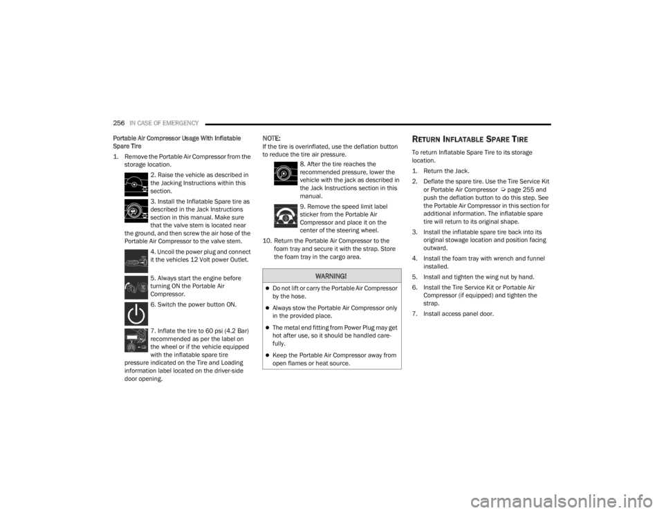
1. Remove the Portable Air Compressor from the storage location.
2. Raise the vehicle as described in
the Jacking Instructions within this
section.
3. Install the Inflatable Spare tire as
described in the Jack Instructions
section in this manual. Make sure
that the valve stem is located near
the ground, and then screw the air hose of the
Portable Air Compressor to the valve stem.
4. Uncoil the power plug and connect
it the vehicles 12 Volt power Outlet.
5. Always start the engine before
turning ON the Portable Air
Compressor.
6. Switch the power button ON.
7. Inflate the tire to 60 psi (4.2 Bar)
recommended as per the label on
the wheel or if the vehicle equipped
with the inflatable spare tire
pressure indicated on the Tire and Loading
information label located on the driver-side
door opening.
NOTE:If the tire is overinflated, use the deflation button
to reduce the tire air pressure.
8. After the tire reaches the
recommended pressure, lower the
vehicle with the jack as described in
the Jack Instructions section in this
manual.
9. Remove the speed limit label
sticker from the Portable Air
Compressor and place it on the
center of the steering wheel.
10. Return the Portable Air Compressor to the foam tray and secure it with the strap. Store
the foam tray in the cargo area.RETURN INFLATABLE SPARE TIRE
To return Inflatable Spare Tire to its storage
location.
1. Return the Jack.
2. Deflate the spare tire. Use the Tire Service Kit
or Portable Air Compressor
Úpage 255 and
push the deflation button to do this step. See
the Portable Air Compressor in this section for
additional information. The inflatable spare
tire will return to its original shape.
3. Install the inflatable spare tire back into its original stowage location and position facing
outward.
4. Install the foam tray with wrench and funnel installed.
5. Install and tighten the wing nut by hand.
6. Install the Tire Service Kit or Portable Air Compressor (if equipped) and tighten the
strap.
7. Install access panel door.
WARNING!
Do not lift or carry the Portable Air Compressor
by the hose.
Always stow the Portable Air Compressor only
in the provided place.
The metal end fitting from Power Plug may get
hot after use, so it should be handled care -
fully.
Keep the Portable Air Compressor away from
open flames or heat source.
21_RUV_OM_EN_USC_t.book Page 256
Page 262 of 348
260IN CASE OF EMERGENCY
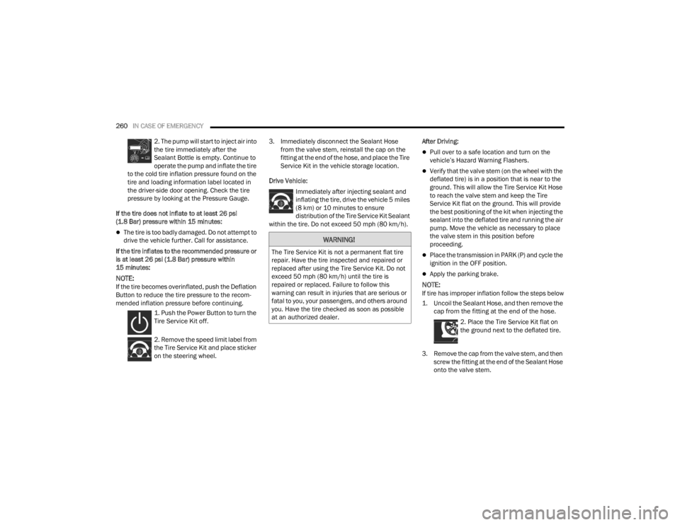
2. The pump will start to inject air into
the tire immediately after the
Sealant Bottle is empty. Continue to
operate the pump and inflate the tire
to the cold tire inflation pressure found on the
tire and loading information label located in
the driver-side door opening. Check the tire
pressure by looking at the Pressure Gauge.
If the tire does not inflate to at least 26 psi
(1.8 Bar) pressure within 15 minutes:
The tire is too badly damaged. Do not attempt to
drive the vehicle further. Call for assistance.
If the tire inflates to the recommended pressure or
is at least 26 psi (1.8 Bar) pressure within
15 minutes:
NOTE:If the tire becomes overinflated, push the Deflation
Button to reduce the tire pressure to the recom -
mended inflation pressure before continuing.
1. Push the Power Button to turn the
Tire Service Kit off.
2. Remove the speed limit label from
the Tire Service Kit and place sticker
on the steering wheel. 3. Immediately disconnect the Sealant Hose
from the valve stem, reinstall the cap on the
fitting at the end of the hose, and place the Tire
Service Kit in the vehicle storage location.
Drive Vehicle: Immediately after injecting sealant and
inflating the tire, drive the vehicle 5 miles
(8 km) or 10 minutes to ensure distribution of the Tire Service Kit Sealant
within the tire. Do not exceed 50 mph (80 km/h). After Driving:
Pull over to a safe location and turn on the
vehicle’s Hazard Warning Flashers.
Verify that the valve stem (on the wheel with the
deflated tire) is in a position that is near to the
ground. This will allow the Tire Service Kit Hose
to reach the valve stem and keep the Tire
Service Kit flat on the ground. This will provide
the best positioning of the kit when injecting the
sealant into the deflated tire and running the air
pump. Move the vehicle as necessary to place
the valve stem in this position before
proceeding.
Place the transmission in PARK (P) and cycle the
ignition in the OFF position.
Apply the parking brake.
NOTE:If tire has improper inflation follow the steps below
1. Uncoil the Sealant Hose, and then remove the
cap from the fitting at the end of the hose.
2. Place the Tire Service Kit flat on
the ground next to the deflated tire.
3. Remove the cap from the valve stem, and then screw the fitting at the end of the Sealant Hose
onto the valve stem.
WARNING!
The Tire Service Kit is not a permanent flat tire
repair. Have the tire inspected and repaired or
replaced after using the Tire Service Kit. Do not
exceed 50 mph (80 km/h) until the tire is
repaired or replaced. Failure to follow this
warning can result in injuries that are serious or
fatal to you, your passengers, and others around
you. Have the tire checked as soon as possible
at an authorized dealer.
21_RUV_OM_EN_USC_t.book Page 260