stop start CHRYSLER VOYAGER 2021 Owner's Guide
[x] Cancel search | Manufacturer: CHRYSLER, Model Year: 2021, Model line: VOYAGER, Model: CHRYSLER VOYAGER 2021Pages: 348, PDF Size: 18.73 MB
Page 129 of 348
STARTING AND OPERATING127
ParkSense, when on, will reduce the volume of
the radio when it is sounding a tone.
Clean the ParkSense sensors regularly, taking
care not to scratch or damage them. The
sensors must not be covered with ice, snow,
slush, mud, dirt, or debris. Failure to do so can
result in the system not working properly. The
ParkSense system might not detect an obstacle
behind the fascia/bumper, or it could provide a
false indication that an obstacle is behind the
fascia/bumper.
ParkSense should be disabled when the liftgate
is in the open position.
Use the ParkSense switch to turn the ParkSense
system off if objects such as bicycle carriers,
trailer hitches, etc. are placed within 12 inches
(30 cm) from the rear fascia/bumper. Failure to
do so can result in the system misinterpreting a
close object as a blockage or sensor problem,
causing the “PARKSENSE UNAVAILABLE WIPE
REAR SENSORS” message to be displayed in
the instrument cluster display.
PARKVIEW REAR BACK UP CAMERA
The ParkView Rear Back Up Camera allows you to
see an on-screen image of the rear surroundings of
your vehicle whenever the gear selector is put into
REVERSE. The image will be displayed on the
touchscreen display along with a caution note
“Check Entire Surroundings” across the top of the
screen. After five seconds, this note will disappear.
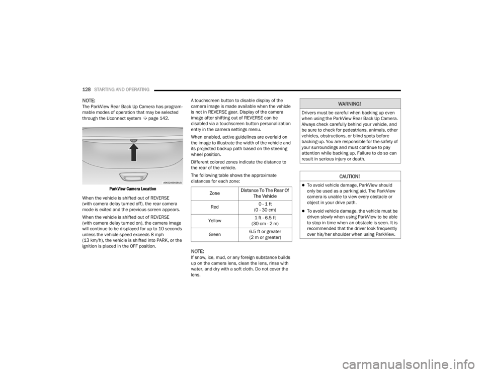
The ParkView Rear Back Up Camera is located on
the rear of the vehicle above the rear license plate.
WARNING!
Drivers must be careful when backing up even
when using ParkSense. Always check carefully
behind your vehicle, look behind you, and be
sure to check for pedestrians, animals, other
vehicles, obstructions, and blind spots before
backing up. You are responsible for safety and
must continue to pay attention to your
surroundings. Failure to do so can result in
serious injury or death.
Before using ParkSense, it is strongly recom -
mended that the ball mount and hitch ball
assembly be disconnected from the vehicle
when the vehicle is not used for towing.
Failure to do so can result in injury or damage
to vehicles or obstacles because the hitch ball
will be much closer to the obstacle than the
rear fascia when the vehicle sounds the
continuous tone. Also, the sensors could
detect the ball mount and hitch ball assembly,
depending on its size and shape, giving a false
indication that an obstacle is behind the
vehicle.
CAUTION!
ParkSense is only a parking aid and it is
unable to recognize every obstacle, including
small obstacles. Parking curbs might be
temporarily detected or not detected at all.
Obstacles located above or below the sensors
will not be detected when they are in close
proximity.
The vehicle must be driven slowly when using
ParkSense in order to be able to stop in time
when an obstacle is detected. It is recom -
mended that the driver looks over his/her
shoulder when using ParkSense.4
21_RUV_OM_EN_USC_t.book Page 127
Page 130 of 348
128STARTING AND OPERATING
NOTE:The ParkView Rear Back Up Camera has program -
mable modes of operation that may be selected
through the Uconnect system
Úpage 142.
ParkView Camera Location
When the vehicle is shifted out of REVERSE
(with camera delay turned off), the rear camera
mode is exited and the previous screen appears.
When the vehicle is shifted out of REVERSE
(with camera delay turned on), the camera image
will continue to be displayed for up to 10 seconds
unless the vehicle speed exceeds 8 mph
(13 km/h), the vehicle is shifted into PARK, or the
ignition is placed in the OFF position. A touchscreen button to disable display of the
camera image is made available when the vehicle
is not in REVERSE gear. Display of the camera
image after shifting out of REVERSE can be
disabled via a touchscreen button personalization
entry in the camera settings menu.
When enabled, active guidelines are overlaid on
the image to illustrate the width of the vehicle and
its projected backup path based on the steering
wheel position.
Different colored zones indicate the distance to
the rear of the vehicle.
The following table shows the approximate
distances for each zone:
NOTE:If snow, ice, mud, or any foreign substance builds
up on the camera lens, clean the lens, rinse with
water, and dry with a soft cloth. Do not cover the
lens.
Zone
Distance To The Rear Of
The Vehicle
Red 0 - 1 ft
(0 - 30 cm)
Yellow 1 ft - 6.5 ft
(30 cm - 2 m)
Green 6.5 ft or greater
(2 m or greater)
WARNING!
Drivers must be careful when backing up even
when using the ParkView Rear Back Up Camera.
Always check carefully behind your vehicle, and
be sure to check for pedestrians, animals, other
vehicles, obstructions, or blind spots before
backing up. You are responsible for the safety of
your surroundings and must continue to pay
attention while backing up. Failure to do so can
result in serious injury or death.
CAUTION!
To avoid vehicle damage, ParkView should
only be used as a parking aid. The ParkView
camera is unable to view every obstacle or
object in your drive path.
To avoid vehicle damage, the vehicle must be
driven slowly when using ParkView to be able
to stop in time when an obstacle is seen. It is
recommended that the driver look frequently
over his/her shoulder when using ParkView.
21_RUV_OM_EN_USC_t.book Page 128
Page 138 of 348
136STARTING AND OPERATING
Towing Requirements — Trailer Lights And
Wiring
Whenever you pull a trailer, regardless of the trailer
size, stoplights and turn signals on the trailer are
required for motoring safety.
The Trailer Tow Package may include a four and
seven-pin wiring harness. Use a factory approved
trailer harness and connector.
NOTE:Do not cut or splice wiring into the vehicle’s wiring
harness.
The electrical connections are all complete to the
vehicle but you must mate the harness to a trailer
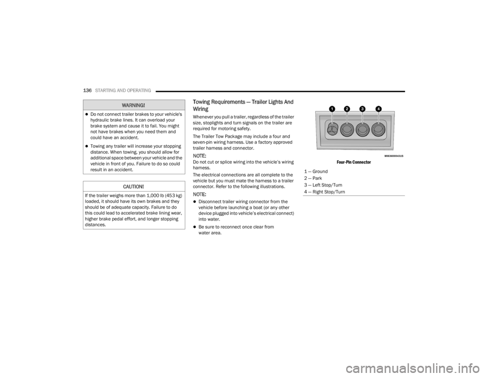
connector. Refer to the following illustrations.
NOTE:
Disconnect trailer wiring connector from the
vehicle before launching a boat (or any other
device plugged into vehicle’s electrical connect)
into water.
Be sure to reconnect once clear from
water area.
Four-Pin Connector
WARNING!
Do not connect trailer brakes to your vehicle's
hydraulic brake lines. It can overload your
brake system and cause it to fail. You might
not have brakes when you need them and
could have an accident.
Towing any trailer will increase your stopping
distance. When towing, you should allow for
additional space between your vehicle and the
vehicle in front of you. Failure to do so could
result in an accident.
CAUTION!
If the trailer weighs more than 1,000 lb (453 kg)
loaded, it should have its own brakes and they
should be of adequate capacity. Failure to do
this could lead to accelerated brake lining wear,
higher brake pedal effort, and longer stopping
distances.
1 — Ground
2 — Park
3 — Left Stop/Turn
4 — Right Stop/Turn
21_RUV_OM_EN_USC_t.book Page 136
Page 139 of 348

STARTING AND OPERATING137
Seven-Pin Connector
TOWING TIPS
Before towing, practice turning, stopping, and
backing up the trailer in an area located away from
heavy traffic.
Automatic Transmission
Select the DRIVE range when towing. The
transmission controls include a drive strategy to
avoid frequent shifting when towing. For increased
engine braking on steep downhill grades, select
the LOW range.
Cruise Control — If Equipped
Do not use on hilly terrain or with heavy loads.
When using the Cruise Control, if you experience
speed drops greater than 10 mph (16 km/h),
disengage until you can get back to cruising
speed.
Use Cruise Control in flat terrain and with light
loads to maximize fuel efficiency.
1 — Battery
2 — Backup Lamps
3 — Right Stop/Turn
4 — Electric Brakes
5 — Ground
6 — Left Stop/Turn
7 — Running Lamps
4
21_RUV_OM_EN_USC_t.book Page 137
Page 141 of 348
STARTING AND OPERATING139
Recreational Towing
Front-Wheel Drive (FWD) Models
Recreational towing is allowed ONLY if the front
wheels are OFF the ground. This may be
accomplished using a tow dolly (front wheels off
the ground) or vehicle trailer (all four wheels off the
ground). If using a tow dolly, follow this procedure:
1. Properly secure the dolly to the tow vehicle, following the dolly manufacturer's
instructions.
2. Drive the front wheels onto the tow dolly.
3. Apply the parking brake.
4. Place the transmission in PARK.
5. Turn the ignition OFF.
6. Properly secure the front wheels to the dolly, following the dolly manufacturer's instructions.
7. Turn the ignition to the ON/RUN mode, but do not start the vehicle.
8. Press and hold the brake pedal.
9. Release the parking brake.
10. Turn the ignition OFF.
11. Release the brake pedal.
DRIVING TIPS
DRIVING ON SLIPPERY SURFACES
Information in this section will aid in safe
controlled launches in adverse conditions.
Acceleration
Rapid acceleration on snow covered, wet, or other
slippery surfaces may cause the driving wheels to
pull erratically to the right or left. This phenomenon
occurs when there is a difference in the surface
traction under the front (driving) wheels.
Traction
When driving on wet or slushy roads, it is possible
for a wedge of water to build-up between the tire
and road surface. This is hydroplaning and may
cause partial or complete loss of vehicle control
and stopping ability. To reduce this possibility, the
following precautions should be observed:
Slow down during rainstorms or when the roads
are slushy.
Slow down if the road has standing water or
puddles.
Replace the tires when tread wear indicators
first become visible.
Keep tires properly inflated.
Maintain sufficient distance between your
vehicle and the vehicle in front of you to avoid a
collision in a sudden stop.
WARNING!
Rapid acceleration on slippery surfaces is
dangerous. Unequal traction can cause sudden
pulling of the front wheels. You could lose
control of the vehicle and possibly have a
collision. Accelerate slowly and carefully
whenever there is likely to be poor traction (ice,
snow, wet, mud, loose sand, etc.).
4
21_RUV_OM_EN_USC_t.book Page 139
Page 142 of 348
140STARTING AND OPERATING
(Continued)
DRIVING THROUGH WATER
Driving through water more than a few inches/
centimeters deep will require extra caution to
ensure safety and prevent damage to your vehicle.
Flowing/Rising Water
Shallow Standing Water
Although your vehicle is capable of driving through
shallow standing water, consider the following
Warnings and Cautions before doing so.
WARNING!
Do not drive on or across a road or path where
water is flowing and/or rising (as in storm
run-off). Flowing water can wear away the road
or path's surface and cause your vehicle to sink
into deeper water. Furthermore, flowing and/or
rising water can carry your vehicle away swiftly.
Failure to follow this warning may result in
injuries that are serious or fatal to you, your
passengers, and others around you.
WARNING!
Driving through standing water limits your
vehicle’s traction capabilities. Do not exceed
5 mph (8 km/h) when driving through
standing water.
Driving through standing water limits your
vehicle’s braking capabilities, which increases
stopping distances. Therefore, after driving
through standing water, drive slowly and
lightly press on the brake pedal several times
to dry the brakes.
Failure to follow these warnings may result in
injuries that are serious or fatal to you, your
passengers, and others around you.
CAUTION!
Always check the depth of the standing water
before driving through it. Never drive through
standing water that is deeper than the bottom
of the tire rims mounted on the vehicle.
Determine the condition of the road or the
path that is under water and if there are any
obstacles in the way before driving through
the standing water.
Do not exceed 5 mph (8 km/h) when driving through standing water. This will minimize
wave effects.
Driving through standing water may cause
damage to your vehicle’s drivetrain compo -
nents. Always inspect your vehicle’s fluids
(i.e., engine oil, transmission, axle, etc.) for
signs of contamination (i.e., fluid that is milky
or foamy in appearance) after driving through
standing water. Do not continue to operate
the vehicle if any fluid appears contaminated,
as this may result in further damage. Such
damage is not covered by the New Vehicle
Limited Warranty.
Getting water inside your vehicle’s engine can
cause it to lock up and stall out, and cause
serious internal damage to the engine. Such
damage is not covered by the New Vehicle
Limited Warranty.
CAUTION!
21_RUV_OM_EN_USC_t.book Page 140
Page 162 of 348
160MULTIMEDIA
RADIO MODE
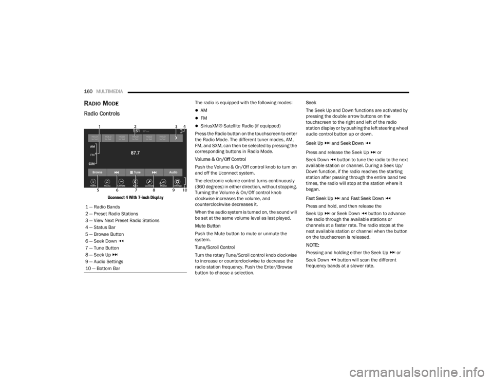
Radio Controls
Uconnect 4 With 7-inch Display
The radio is equipped with the following modes:
AM
FM
SiriusXM® Satellite Radio (if equipped)
Press the Radio button on the touchscreen to enter
the Radio Mode. The different tuner modes, AM,
FM, and SXM, can then be selected by pressing the
corresponding buttons in Radio Mode.
Volume & On/Off Control
Push the Volume & On/Off control knob to turn on
and off the Uconnect system.
The electronic volume control turns continuously
(360 degrees) in either direction, without stopping.
Turning the Volume & On/Off control knob
clockwise increases the volume, and
counterclockwise decreases it.
When the audio system is turned on, the sound will
be set at the same volume level as last played.
Mute Button
Push the Mute button to mute or unmute the
system.
Tune/Scroll Control
Turn the rotary Tune/Scroll control knob clockwise
to increase or counterclockwise to decrease the
radio station frequency. Push the Enter/Browse
button to choose a selection. Seek
The Seek Up and Down functions are activated by
pressing the double arrow buttons on the
touchscreen to the right and left of the radio
station display or by pushing the left steering wheel
audio control button up or down.
Seek Up
and Seek Down
Press and release the Seek Up or
Seek Down button to tune the radio to the next
available station or channel. During a Seek Up/
Down function, if the radio reaches the starting
station after passing through the entire band two
times, the radio will stop at the station where it
began.
Fast Seek Up and Fast Seek Down
Press and hold, and then release the
Seek Up or Seek Down button to advance the radio through the available stations or
channels at a faster rate. The radio stops at the
next available station or channel when the button
on the touchscreen is released.
NOTE:
Pressing and holding either the Seek Up or
Seek Down button will scan the different
frequency bands at a slower rate.
1 — Radio Bands
2 — Preset Radio Stations
3 — View Next Preset Radio Stations
4 — Status Bar
5 — Browse Button
6 — Seek Down
7 — Tune Button
8 — Seek Up
9 — Audio Settings
10 — Bottom Bar
21_RUV_OM_EN_USC_t.book Page 160
Page 188 of 348
186 (Continued)
SAFETY
SAFETY FEATURES
ANTI-LOCK BRAKE SYSTEM (ABS)
The ABS provides increased vehicle stability and
brake performance under most braking conditions.
The system automatically prevents wheel lock and
enhances vehicle control during braking.
The ABS performs a self-check cycle to ensure that
the ABS is working properly each time the vehicle
is started and driven. During this self-check, you
may hear a slight clicking sound as well as some
related motor noises.
The ABS is activated during braking when the
system detects one or more wheels are beginning
to lock. Road conditions such as ice, snow, gravel,
bumps, railroad tracks, loose debris, or panic stops
may increase the likelihood of ABS activation(s).
You also may experience the following normal
characteristics when the ABS activates:
ABS motor noise or clicking sounds (you may
continue to hear for a short time after the stop)
Brake pedal pulsations
A slight drop of the brake pedal at the end of the
stopThe ABS is designed to function with the Original
Equipment Manufacturer (OEM) tires. Modification
may result in degraded ABS performance.
Anti-Lock Brake System (ABS) Warning
Light
The yellow ABS Warning Light will turn on when the
ignition is placed in the ON/RUN mode and may
stay on for as long as four seconds.
If the ABS Warning Light remains on or comes on
while driving, it indicates that the anti-lock portion
of the brake system is not functioning and that
service is required. However, the conventional
brake system will continue to operate normally if
the ABS Warning Light is on.
WARNING!
The ABS contains sophisticated electronic
equipment that may be susceptible to interfer
-
ence caused by improperly installed or high
output radio transmitting equipment. This
interference can cause possible loss of
anti-lock braking capability. Installation of
such equipment should be performed by qual -
ified professionals.
Pumping of the Anti-Lock Brakes will diminish
their effectiveness and may lead to a collision.
Pumping makes the stopping distance longer.
Just press firmly on your brake pedal when you
need to slow down or stop.
The ABS cannot prevent the natural laws of
physics from acting on the vehicle, nor can it
increase braking or steering efficiency beyond
that afforded by the condition of the vehicle
brakes and tires or the traction afforded.
The ABS cannot prevent collisions, including
those resulting from excessive speed in turns,
following another vehicle too closely, or hydro -
planing.
The capabilities of an ABS equipped vehicle
must never be exploited in a reckless or
dangerous manner that could jeopardize the
user’s safety or the safety of others.
WARNING!
21_RUV_OM_EN_USC_t.book Page 186
Page 189 of 348
SAFETY187
If the ABS Warning Light is on, the brake system
should be serviced as soon as possible to restore
the benefits of Anti-Lock Brakes. If the ABS
Warning Light does not come on when the ignition
is placed in the ON/RUN mode, have the light
repaired as soon as possible.
ELECTRONIC BRAKE CONTROL (EBC)
S
YSTEM
Your vehicle is equipped with an advanced
Electronic Brake Control (EBC) system. This system
includes Anti-Lock Brake System (ABS), Brake
Assist System (BAS), Electronic Brake Force
Distribution (EBD), Electronic Roll Mitigation
(ERM), Electronic Stability Control (ESC), Hill Start
Assist (HSA), and Traction Control System
(TCS).These systems work together to enhance
both vehicle stability and control in various driving
conditions.
Your vehicle may also be equipped with Dynamic
Steering Torque (DST), Ready Alert Braking (RAB),
Rain Brake Support (RBS) and Trailer Sway Control
(TSC).
Brake Assist System (BAS)
The BAS is designed to optimize the vehicle’s
braking capability during emergency braking
maneuvers. The system detects an emergency
braking situation by sensing the rate and amount
of brake application and then applies optimum
pressure to the brakes. This can help reduce
braking distances. The BAS complements the
Anti-Lock Brake System (ABS). Applying the brakes
very quickly results in the best BAS assistance. To
receive the benefit of the system, you must apply
continuous braking pressure during the stopping
sequence (do not “pump” the brakes). Do not
reduce brake pedal pressure unless braking is no
longer desired. Once the brake pedal is released,
the BAS is deactivated.
Brake System Warning Light
The red Brake System Warning Light will turn on
when the ignition is placed in the ON/RUN mode
and may stay on for as long as four seconds.
If the Brake System Warning Light remains on or
comes on while driving, it indicates that the brake
system is not functioning properly and that
immediate service is required. If the Brake System
Warning Light does not come on when the ignition
is placed in the ON/RUN mode, have the light
repaired as soon as possible.
Dynamic Steering Torque (DST)
DST is a feature of the ESC and Electric Power
Steering (EPS) modules that provides torque at the
steering wheel for certain driving conditions in
which the ESC module is detecting vehicle
instability. The torque that the steering wheel
receives is only meant to help the driver realize
optimal steering behavior in order to reach/
maintain vehicle stability. The only notification the
driver receives that the feature is active, is the
torque applied to the steering wheel.
WARNING!
The Brake Assist System (BAS) cannot prevent
the natural laws of physics from acting on the
vehicle, nor can it increase the traction afforded
by prevailing road conditions. BAS cannot
prevent collisions, including those resulting from
excessive speed in turns, driving on very slippery
surfaces, or hydroplaning. The capabilities of a
BAS-equipped vehicle must never be exploited in
a reckless or dangerous manner, which could
jeopardize the user's safety or the safety of
others.
6
21_RUV_OM_EN_USC_t.book Page 187
Page 192 of 348
190SAFETY
ESC Activation/Malfunction Indicator Light
And ESC OFF Indicator Light
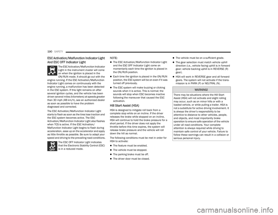
The ESC Activation/Malfunction Indicator
Light in the instrument cluster will come
on when the ignition is placed in the
ON/RUN mode. It should go out with the
engine running. If the ESC Activation/Malfunction
Indicator Light comes on continuously with the
engine running, a malfunction has been detected
in the ESC system. If this light remains on after
several ignition cycles, and the vehicle has been
driven several miles (kilometers) at speeds greater
than 30 mph (48 km/h), see an authorized dealer
as soon as possible to have the problem
diagnosed and corrected.
The ESC Activation/Malfunction Indicator Light
starts to flash as soon as the tires lose traction and
the ESC system becomes active. The ESC
Activation/Malfunction Indicator Light also flashes
when TCS is active. If the ESC Activation/
Malfunction Indicator Light begins to flash during
acceleration, ease up on the accelerator and apply
as little throttle as possible. Be sure to adapt your
speed and driving to the prevailing road conditions.
The ESC OFF Indicator Light indicates
that the Electronic Stability Control (ESC)
is in a reduced mode.
NOTE:
The ESC Activation/Malfunction Indicator Light
and the ESC OFF Indicator Light come on
momentarily each time the ignition is placed in
the ON/RUN position.
Each time the ignition is placed in the ON/RUN
position, the ESC system will be on even if it was
turned off previously.
The ESC system will make buzzing or clicking
sounds when it is active. This is normal; the
sounds will stop when ESC becomes inactive
following the maneuver that caused the ESC
activation.
Hill Start Assist (HSA)
HSA is designed to mitigate roll back from a
complete stop while on an incline. If the driver
releases the brake while stopped on an incline,
HSA will continue to hold the brake pressure for a
short period. If the driver does not apply the
throttle before this time expires, the system will
release brake pressure and the vehicle will roll
down the hill as normal.
The following conditions must be met in order for
HSA to activate:
The feature must be enabled.
The vehicle must be stopped.
The parking brake must be off.
The driver door must be closed.
The vehicle must be on a sufficient grade.
The gear selection must match vehicle uphill
direction (i.e., vehicle facing uphill is in forward
gear; vehicle backing uphill is in REVERSE (R)
gear).
HSA will work in REVERSE gear and all forward
gears. The system will not activate if the trans -
mission is in PARK (P) or NEUTRAL (N).
WARNING!
There may be situations where the Hill Start
Assist (HSA) will not activate and slight rolling
may occur, such as on minor hills or with a
loaded vehicle, or while pulling a trailer. HSA is
not a substitute for active driving involvement. It
is always the driver’s responsibility to be
attentive to distance to other vehicles, people,
and objects, and most importantly brake
operation to ensure safe operation of the vehicle
under all road conditions. Your complete
attention is always required while driving to
maintain safe control of your vehicle. Failure to
follow these warnings can result in a collision or
serious personal injury.
21_RUV_OM_EN_USC_t.book Page 190