brake fluid CHRYSLER VOYAGER 2021 Owners Manual
[x] Cancel search | Manufacturer: CHRYSLER, Model Year: 2021, Model line: VOYAGER, Model: CHRYSLER VOYAGER 2021Pages: 348, PDF Size: 18.73 MB
Page 7 of 348
5
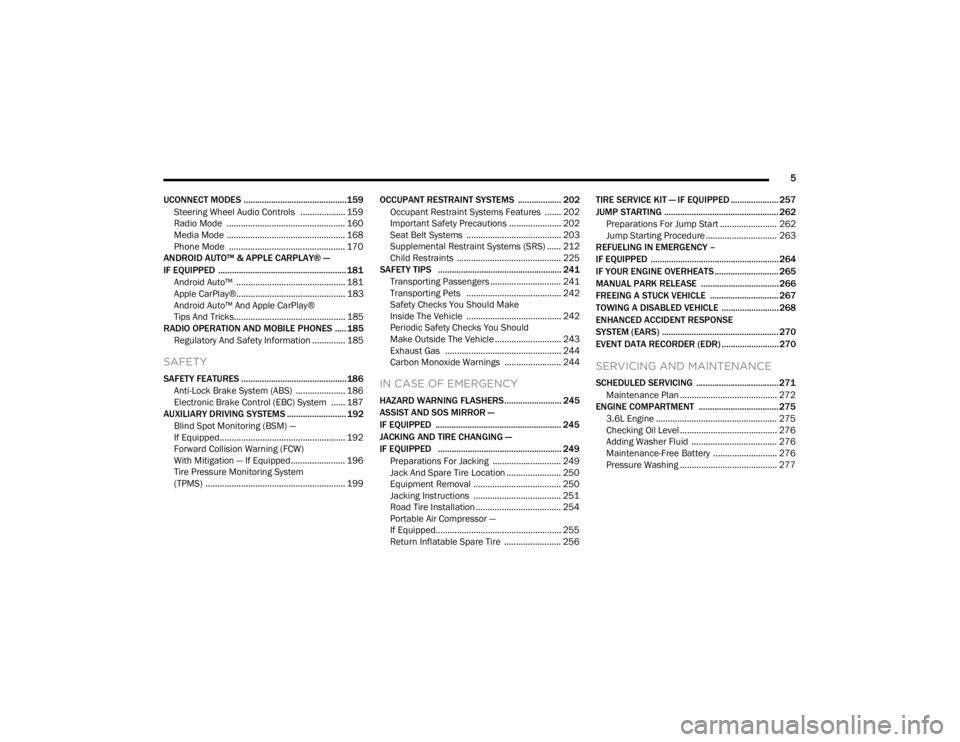
UCONNECT MODES ............................................. 159 Steering Wheel Audio Controls ................... 159
Radio Mode .................................................. 160
Media Mode .................................................. 168
Phone Mode ................................................. 170
ANDROID AUTO™ & APPLE CARPLAY® —
IF EQUIPPED ........................................................ 181
Android Auto™ .............................................. 181Apple CarPlay®.............................................. 183Android Auto™ And Apple CarPlay®
Tips And Tricks............................................... 185
RADIO OPERATION AND MOBILE PHONES ..... 185
Regulatory And Safety Information .............. 185
SAFETY
SAFETY FEATURES .............................................. 186Anti-Lock Brake System (ABS) ..................... 186
Electronic Brake Control (EBC) System ...... 187
AUXILIARY DRIVING SYSTEMS .......................... 192
Blind Spot Monitoring (BSM) —
If Equipped..................................................... 192
Forward Collision Warning (FCW)
With Mitigation — If Equipped....................... 196
Tire Pressure Monitoring System
(TPMS) ........................................................... 199 OCCUPANT RESTRAINT SYSTEMS ................... 202
Occupant Restraint Systems Features ....... 202
Important Safety Precautions ...................... 202Seat Belt Systems ........................................ 203Supplemental Restraint Systems (SRS) ...... 212Child Restraints ............................................ 225
SAFETY TIPS ...................................................... 241
Transporting Passengers .............................. 241Transporting Pets ........................................ 242Safety Checks You Should Make
Inside The Vehicle ........................................ 242Periodic Safety Checks You Should
Make Outside The Vehicle ............................ 243
Exhaust Gas ................................................. 244
Carbon Monoxide Warnings ........................ 244IN CASE OF EMERGENCY
HAZARD WARNING FLASHERS......................... 245
ASSIST AND SOS MIRROR —
IF EQUIPPED ....................................................... 245
JACKING AND TIRE CHANGING —
IF EQUIPPED ...................................................... 249
Preparations For Jacking ............................. 249
Jack And Spare Tire Location ....................... 250
Equipment Removal ..................................... 250
Jacking Instructions ..................................... 251
Road Tire Installation .................................... 254
Portable Air Compressor —
If Equipped..................................................... 255Return Inflatable Spare Tire ........................ 256 TIRE SERVICE KIT — IF EQUIPPED ..................... 257
JUMP STARTING .................................................. 262
Preparations For Jump Start ........................ 262Jump Starting Procedure .............................. 263
REFUELING IN EMERGENCY –
IF EQUIPPED ........................................................ 264
IF YOUR ENGINE OVERHEATS ............................ 265
MANUAL PARK RELEASE .................................. 266
FREEING A STUCK VEHICLE .............................. 267
TOWING A DISABLED VEHICLE ......................... 268
ENHANCED ACCIDENT RESPONSE
SYSTEM (EARS) ................................................... 270
EVENT DATA RECORDER (EDR) ......................... 270
SERVICING AND MAINTENANCE
SCHEDULED SERVICING .................................... 271 Maintenance Plan ......................................... 272
ENGINE COMPARTMENT ................................... 275
3.6L Engine ................................................... 275
Checking Oil Level ......................................... 276
Adding Washer Fluid .................................... 276
Maintenance-Free Battery ........................... 276
Pressure Washing ......................................... 277
21_RUV_OM_EN_USC_t.book Page 5
Page 8 of 348
6
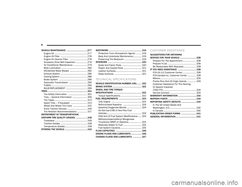
VEHICLE MAINTENANCE .................................... 277 Engine Oil ...................................................... 277Engine Oil Filter ............................................ 278
Engine Air Cleaner Filter ............................. 278
Accessory Drive Belt Inspection ................... 279
Air Conditioner Maintenance ....................... 279
Body Lubrication ........................................... 282Windshield Wiper Blades ............................. 282
Exhaust System ............................................ 285
Cooling System .............................................. 286Brake System ............................................... 289
Automatic Transmission .............................. 290FUSES............................................................. 290
BULB REPLACEMENT ................................... 299
TIRES .................................................................... 301
Tire Safety Information ............................... 301
Tires — General Information ........................ 309
Tire Types ....................................................... 313
Spare Tires — If Equipped ........................... 313
Wheel And Wheel Trim Care ....................... 315
Snow Traction Devices ................................. 316Tire Rotation Recommendations ................. 317
DEPARTMENT OF TRANSPORTATION
UNIFORM TIRE QUALITY GRADES .................... 318
Treadwear ...................................................... 318Traction Grades ............................................. 318
Temperature Grades ..................................... 318
STORING THE VEHICLE ....................................... 319 BODYWORK ......................................................... 319
Protection From Atmospheric Agents ......... 319Body And Underbody Maintenance.............. 319Preserving The Bodywork ............................. 319
INTERIORS .......................................................... 320
Seats And Fabric Parts ................................. 320
Plastic And Coated Parts .............................. 321Leather Surfaces ........................................... 321Glass Surfaces ............................................. 321
TECHNICAL SPECIFICATIONS
VEHICLE IDENTIFICATION NUMBER (VIN) ........ 322
BRAKE SYSTEM ................................................... 322
WHEEL AND TIRE TORQUE
SPECIFICATIONS ................................................ 322
Torque Specifications ................................... 322
FUEL REQUIREMENTS ....................................... 323
3.6L Engine .................................................. 323
Reformulated Gasoline .............................. 324Gasoline/Oxygenate Blends ........................ 324
Do Not Use E-85 In Non-Flex Fuel
Vehicles.......................................................... 324CNG And LP Fuel System Modifications ...... 324Methylcyclopentadienyl Manganese
Tricarbonyl (MMT) In Gasoline...................... 324Materials Added To Fuel .............................. 325Fuel System Cautions ................................... 325
FLUID CAPACITIES ............................................ 326
ENGINE FLUIDS AND LUBRICANTS .................. 326
CHASSIS FLUIDS AND LUBRICANTS ............... 327
CUSTOMER ASSISTANCE
SUGGESTIONS FOR OBTAINING
SERVICE FOR YOUR VEHICLE ............................ 328
Prepare For The Appointment ...................... 328
Prepare A List ................................................ 328
Be Reasonable With Requests..................... 328
IF YOU NEED ASSISTANCE ................................ 328
FCA US LLC Customer Center....................... 328
FCA Canada Inc. Customer Center .............. 328
Mexico............................................................ 329
Puerto Rico And US Virgin Islands ............... 329
Customer Assistance For The Hearing
Or Speech Impaired
(TDD/TTY) ...................................................... 329
Service Contract ........................................... 329
WARRANTY INFORMATION ................................ 330
MOPAR® PARTS ................................................. 330
REPORTING SAFETY DEFECTS .......................... 330
In The 50 United States And
Washington, D.C............................................ 330
In Canada ...................................................... 330
PUBLICATION ORDER FORMS .......................... 331
GENERAL INFORMATION.................................... 331
21_RUV_OM_EN_USC_t.book Page 6
Page 99 of 348
GETTING TO KNOW YOUR INSTRUMENT PANEL97
To Reset A Trip Function
Push and hold the OK button to reset the currently
displayed trip.
WARNING LIGHTS AND MESSAGES
The warning/indicator lights will illuminate in the
instrument panel together with a dedicated
message and/or acoustic signal when applicable.
These indications are indicative and precautionary
and as such must not be considered as exhaustive
and/or alternative to the information contained in
the Owner’s Manual, which you are advised to read
carefully in all cases. Always refer to the
information in this chapter in the event of a failure
indication. All active telltales will display first if
applicable. The system check menu may appear
different based upon equipment options and
current vehicle status. Some telltales are optional
and may not appear.
RED WARNING LIGHTS
Air Bag Warning Light
This warning light will illuminate to
indicate a fault with the air bag, and will
turn on for four to eight seconds as a bulb
check when the ignition is placed in the
ON/RUN or ACC/ON/RUN position. This light will
illuminate with a single chime when a fault with the
air bag has been detected, it will stay on until the fault is cleared. If the light is either not on during
startup, stays on, or turns on while driving, have
the system inspected at an authorized dealer as
soon as possible.
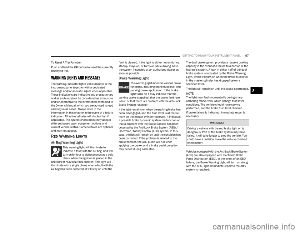
Brake Warning Light
This warning light monitors various brake
functions, including brake fluid level and
parking brake application. If the brake
light turns on it may indicate that the
parking brake is applied, that the brake fluid level
is low, or that there is a problem with the Anti-Lock
Brake System reservoir.
If the light remains on when the parking brake has
been disengaged, and the fluid level is at the full
mark on the master cylinder reservoir, it indicates
a possible brake hydraulic system malfunction or
that a problem with the Brake Booster has been
detected by the Anti-Lock Brake System (ABS) /
Electronic Stability Control (ESC) system. In this
case, the light will remain on until the condition has
been corrected. If the problem is related to the
brake booster, the ABS pump will run when
applying the brake, and a brake pedal pulsation
may be felt during each stop. The dual brake system provides a reserve braking
capacity in the event of a failure to a portion of the
hydraulic system. A leak in either half of the dual
brake system is indicated by the Brake Warning
Light, which will turn on when the brake fluid level
in the master cylinder has dropped below a
specified level.
The light will remain on until the cause is corrected.
NOTE:The light may flash momentarily during sharp
cornering maneuvers, which change fluid level
conditions. The vehicle should have service
performed, and the brake fluid level checked.
If brake failure is indicated, immediate repair is
necessary.
Vehicles equipped with the Anti-Lock Brake System
(ABS) are also equipped with Electronic Brake
Force Distribution (EBD). In the event of an EBD
failure, the Brake Warning Light will turn on along
with the ABS Light. Immediate repair to the ABS
system is required.
WARNING!
Driving a vehicle with the red brake light on is
dangerous. Part of the brake system may have
failed. It will take longer to stop the vehicle. You
could have a collision. Have the vehicle checked
immediately.
3
21_RUV_OM_EN_USC_t.book Page 97
Page 102 of 348
100GETTING TO KNOW YOUR INSTRUMENT PANEL
Vehicle Security Warning Light —
If Equipped
This warning light will flash at a fast rate
for approximately 15 seconds when the
vehicle security system is arming, and
then will flash slowly until the vehicle is
disarmed.
YELLOW WARNING LIGHTS
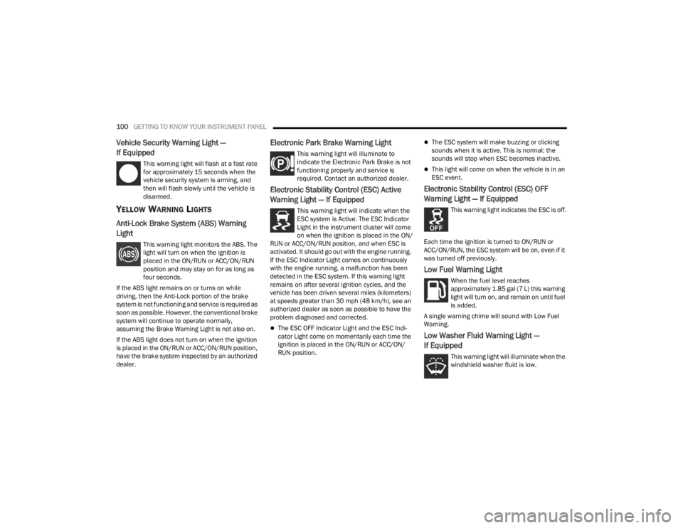
Anti-Lock Brake System (ABS) Warning
Light
This warning light monitors the ABS. The
light will turn on when the ignition is
placed in the ON/RUN or ACC/ON/RUN
position and may stay on for as long as
four seconds.
If the ABS light remains on or turns on while
driving, then the Anti-Lock portion of the brake
system is not functioning and service is required as
soon as possible. However, the conventional brake
system will continue to operate normally,
assuming the Brake Warning Light is not also on.
If the ABS light does not turn on when the ignition
is placed in the ON/RUN or ACC/ON/RUN position,
have the brake system inspected by an authorized
dealer.
Electronic Park Brake Warning Light
This warning light will illuminate to
indicate the Electronic Park Brake is not
functioning properly and service is
required. Contact an authorized dealer.
Electronic Stability Control (ESC) Active
Warning Light — If Equipped
This warning light will indicate when the
ESC system is Active. The ESC Indicator
Light in the instrument cluster will come
on when the ignition is placed in the ON/
RUN or ACC/ON/RUN position, and when ESC is
activated. It should go out with the engine running.
If the ESC Indicator Light comes on continuously
with the engine running, a malfunction has been
detected in the ESC system. If this warning light
remains on after several ignition cycles, and the
vehicle has been driven several miles (kilometers)
at speeds greater than 30 mph (48 km/h), see an
authorized dealer as soon as possible to have the
problem diagnosed and corrected.
The ESC OFF Indicator Light and the ESC Indi -
cator Light come on momentarily each time the
ignition is placed in the ON/RUN or ACC/ON/
RUN position.
The ESC system will make buzzing or clicking
sounds when it is active. This is normal; the
sounds will stop when ESC becomes inactive.
This light will come on when the vehicle is in an
ESC event.
Electronic Stability Control (ESC) OFF
Warning Light — If Equipped
This warning light indicates the ESC is off.
Each time the ignition is turned to ON/RUN or
ACC/ON/RUN, the ESC system will be on, even if it
was turned off previously.
Low Fuel Warning Light
When the fuel level reaches
approximately 1.85 gal (7 L) this warning
light will turn on, and remain on until fuel
is added.
A single warning chime will sound with Low Fuel
Warning.
Low Washer Fluid Warning Light —
If Equipped
This warning light will illuminate when the
windshield washer fluid is low.
21_RUV_OM_EN_USC_t.book Page 100
Page 119 of 348
STARTING AND OPERATING117
The following indicators should be used to ensure
that you have properly engaged the transmission
into the PARK position:
Look at the transmission gear position display
and verify that it indicates the PARK position (P),
and is not blinking.
With brake pedal released, verify that the gear
selector will not move out of PARK.
REVERSE (R)
This range is for moving the vehicle backward.
Shift into REVERSE only after the vehicle has come
to a complete stop.
NEUTRAL (N)
Use this range when the vehicle is standing for
prolonged periods with the engine running. The
engine may be started in this range. Apply the
parking brake and shift the transmission into PARK
if you must exit the vehicle.
DRIVE (D)
This range should be used for most city and
highway driving. It provides the smoothest upshifts
and downshifts, and the best fuel economy. The
transmission automatically upshifts through all
forward gears. The DRIVE position provides
optimum driving characteristics under all normal
operating conditions.
If the transmission temperature exceeds normal
operating limits, the transmission controller may
modify the transmission shift schedule, reduce
engine torque, and/or expand the range of torque
converter clutch engagement. This is done to
prevent transmission damage due to overheating.
If the transmission becomes extremely hot, the
“Transmission Temperature Warning Light” will
illuminate, a warning message will appear in the
instrument cluster, and the transmission may
operate differently until the transmission cools
down. During cold temperatures, transmission operation
may be modified depending on engine and
transmission temperature as well as vehicle
speed. This feature improves warm up time of the
engine and transmission to achieve maximum
efficiency. Engagement of the torque converter
clutch, and shifts into EIGHTH or NINTH gear, are
inhibited until the transmission fluid is warm
Úpage 118. Normal operation will resume once
the transmission temperature has risen to a
suitable level.
LOW (L)
Use this range for engine braking when
descending very steep grades. In this range, the
transmission will downshift for increased engine
braking. To access the LOW position, push down
on the gear selector and rotate it fully clockwise.
Transmission Limp Home Mode
Transmission function is monitored electronically
for abnormal conditions. If a condition is detected
that could result in transmission damage,
Transmission Limp Home Mode is activated. In this
mode, the transmission may operate only in a fixed
gear, or may remain in NEUTRAL. The Malfunction
Indicator Light (MIL) may be illuminated. Limp
Home Mode may allow the vehicle to be driven to
an authorized dealer for service without damaging
the transmission.
WARNING!
Do not coast in NEUTRAL and never turn off the
ignition to coast down a hill. These are unsafe
practices that limit your response to changing
traffic or road conditions. You might lose control
of the vehicle and have a collision.
CAUTION!
Towing the vehicle, coasting, or driving for any
other reason with the transmission in NEUTRAL
can cause severe transmission damage.
If Recreational Towing
Úpage 138.
If Towing A Disabled Vehicle
Úpage 268.
4
21_RUV_OM_EN_USC_t.book Page 117
Page 121 of 348
STARTING AND OPERATING119
NOTE:
Even if the power steering assistance is no
longer operational, it is still possible to steer
the vehicle. Under these conditions there will
be a substantial increase in steering effort,
especially at low speeds and during parking
maneuvers.
The power steering system is fully electric; it
requires no power steering fluid.
If the condition persists, see an authorized
dealer for service.
STOP/START SYSTEM — IF EQUIPPED
The Stop/Start function is developed to reduce
fuel consumption. The system will stop the engine
automatically during a vehicle stop if the required
conditions are met. Releasing the brake pedal,
pressing the accelerator pedal or shifting out of
DRIVE (D) will automatically re-start the engine.
This vehicle has been upgraded with a heavy duty
starter, enhanced battery, and other upgraded
engine parts to handle the additional engine starts.
AUTOSTOP MODE
The Stop/Start feature is enabled after every
normal customer engine start. At that time, the
system will go into STOP/START READY and if
all other conditions are met, can go into a
STOP/START AUTOSTOP ACTIVE. To Activate Auto STOP/START, The Following Must
Occur:
The system must be in STOP/START READY
state. A STOP/START READY message will be
displayed in the instrument cluster within the
Stop/Start section
Úpage 97.
The vehicle must be completely stopped.
The gear selector must be in a forward gear and
the brake pedal pressed.
The engine will shut down, the tachometer will
move to the zero position and the Stop/Start
telltale will illuminate indicating you are in
Autostop. Customer settings will be maintained
throughout the Auto Stop/Start process.
POSSIBLE REASONS THE ENGINE DOES
N
OT AUTOSTOP
Prior to engine shut down, the system will check
many safety and comfort conditions for Stop/Start
and ensure they are fulfilled. Detailed information
about the operation of the Stop/Start system
may be viewed in the instrument cluster display
Stop/Start screen. In the following situations the
engine will not stop:
If Stop/Start is manually disabled by the
Stop/Start OFF button.
Driver’s seat belt is not buckled.
Driver’s door is not closed.
Battery temperature is too warm or cold.
Battery charge is low. During this time a
message will display "Stop/Start Not Ready
Battery Charging".
The vehicle is on a steep grade.
Cabin heating or cooling is in process and an
acceptable cabin temperature has not been
achieved.
HVAC is set to full defrost mode at a high blower
speed.
HVAC set to MAX A/C.
Engine has not reached normal operating
temperature.
The transmission is not in a forward gear.
Hood is open.
Brake pedal is not pressed with sufficient pres -
sure.
Accelerator pedal input.
Engine temperature too high.
5 mph (8 km/h) threshold not achieved from
previous Autostop.
Steering angle beyond threshold.
It may be possible for the vehicle to be driven
several times without the Stop/Start system going
into a STOP/START READY state under more
extreme conditions of the items listed above.
4
21_RUV_OM_EN_USC_t.book Page 119
Page 132 of 348
130STARTING AND OPERATING
Payload
The payload of a vehicle is defined as the allowable
load weight a truck can carry, including the weight
of the driver, all passengers, options and cargo.
Gross Axle Weight Rating (GAWR)
The GAWR is the maximum permissible load on the
front and rear axles. The load must be distributed
in the cargo area so that the GAWR of each axle is
not exceeded.
Each axle GAWR is determined by the components
in the system with the lowest load carrying capacity
(axle, springs, tires or wheels). Heavier axles or
suspension components sometimes specified by
purchasers for increased durability does not
necessarily increase the vehicle's GVWR.
Tire Size
The tire size on the Vehicle Certification Label
represents the actual tire size on your vehicle.
Replacement tires must be equal to the load
capacity of this tire size.
Rim Size
This is the rim size that is appropriate for the tire
size listed.
Inflation Pressure
This is the cold tire inflation pressure for your
vehicle for all loading conditions up to full GAWR.
Curb Weight
The curb weight of a vehicle is defined as the total
weight of the vehicle with all fluids, including
vehicle fuel, at full capacity conditions, and with no
occupants or cargo loaded into the vehicle. The
front and rear curb weight values are determined
by weighing your vehicle on a commercial scale
before any occupants or cargo are added.
Loading
The actual total weight and the weight of the front
and rear of your vehicle at the ground can best be
determined by weighing it when it is loaded and
ready for operation.
The entire vehicle should first be weighed on a
commercial scale to ensure that the GVWR has not
been exceeded. The weight on the front and rear of
the vehicle should then be determined separately
to be sure that the load is properly distributed over
the front and rear axle. Weighing the vehicle may
show that the GAWR of either the front or rear axles
has been exceeded but the total load is within the
specified GVWR. If so, weight must be shifted from
front to rear or rear to front as appropriate until the
specified weight limitations are met. Store the
heavier items down low and be sure that the
weight is distributed equally. Stow all loose items
securely before driving. Improper weight distributions can have an adverse
effect on the way your vehicle steers and handles
and the way the brakes operate.
TRAILER TOWING
In this section you will find safety tips and
information on limits to the type of towing you can
reasonably do with your vehicle. Before towing a
trailer, carefully review this information to tow your
load as efficiently and safely as possible.
To maintain the New Vehicle Limited Warranty
coverage, follow the requirements and
recommendations in this manual concerning
vehicles used for trailer towing.
COMMON TOWING DEFINITIONS
The following trailer towing related definitions will
assist you in understanding the following
information:
CAUTION!
Do not load your vehicle any heavier than the
GVWR or the maximum front and rear GAWR. If
you do, parts on your vehicle can break, or it can
change the way your vehicle handles. This could
cause you to lose control. Also overloading can
shorten the life of your vehicle.
21_RUV_OM_EN_USC_t.book Page 130
Page 142 of 348
140STARTING AND OPERATING
(Continued)
DRIVING THROUGH WATER
Driving through water more than a few inches/
centimeters deep will require extra caution to
ensure safety and prevent damage to your vehicle.
Flowing/Rising Water
Shallow Standing Water
Although your vehicle is capable of driving through
shallow standing water, consider the following
Warnings and Cautions before doing so.
WARNING!
Do not drive on or across a road or path where
water is flowing and/or rising (as in storm
run-off). Flowing water can wear away the road
or path's surface and cause your vehicle to sink
into deeper water. Furthermore, flowing and/or
rising water can carry your vehicle away swiftly.
Failure to follow this warning may result in
injuries that are serious or fatal to you, your
passengers, and others around you.
WARNING!
Driving through standing water limits your
vehicle’s traction capabilities. Do not exceed
5 mph (8 km/h) when driving through
standing water.
Driving through standing water limits your
vehicle’s braking capabilities, which increases
stopping distances. Therefore, after driving
through standing water, drive slowly and
lightly press on the brake pedal several times
to dry the brakes.
Failure to follow these warnings may result in
injuries that are serious or fatal to you, your
passengers, and others around you.
CAUTION!
Always check the depth of the standing water
before driving through it. Never drive through
standing water that is deeper than the bottom
of the tire rims mounted on the vehicle.
Determine the condition of the road or the
path that is under water and if there are any
obstacles in the way before driving through
the standing water.
Do not exceed 5 mph (8 km/h) when driving through standing water. This will minimize
wave effects.
Driving through standing water may cause
damage to your vehicle’s drivetrain compo -
nents. Always inspect your vehicle’s fluids
(i.e., engine oil, transmission, axle, etc.) for
signs of contamination (i.e., fluid that is milky
or foamy in appearance) after driving through
standing water. Do not continue to operate
the vehicle if any fluid appears contaminated,
as this may result in further damage. Such
damage is not covered by the New Vehicle
Limited Warranty.
Getting water inside your vehicle’s engine can
cause it to lock up and stall out, and cause
serious internal damage to the engine. Such
damage is not covered by the New Vehicle
Limited Warranty.
CAUTION!
21_RUV_OM_EN_USC_t.book Page 140
Page 245 of 348
SAFETY243
(Continued)
PERIODIC SAFETY CHECKS YOU SHOULD
M
AKE OUTSIDE THE VEHICLE
Tires
Examine tires for excessive tread wear and uneven
wear patterns. Check for stones, nails, glass, or
other objects lodged in the tread or sidewall.
Inspect the tread for cuts and cracks. Inspect
sidewalls for cuts, cracks, and bulges. Check the
lug nut/bolt torque for tightness. Check the tires
(including spare) for proper cold inflation pressure.
Lights
Have someone observe the operation of brake
lights and exterior lights while you work the
controls. Check turn signal and high beam
indicator lights on the instrument panel.
Door Latches
Check for proper closing, latching, and locking.
Fluid Leaks
Check area under the vehicle after overnight
parking for fuel, coolant, oil, or other fluid leaks.
Also, if gasoline fumes are detected or if fuel or
brake fluid leaks are suspected, the cause should
be located and corrected immediately.
ALWAYS REMOVE THE EXISTING FLOOR MAT
FROM THE VEHICLE before installing any
other floor mat. NEVER install or stack an
additional floor mat on top of an existing floor
mat.
ONLY install floor mats designed to fit your
vehicle. NEVER install a floor mat that cannot
be properly attached and secured to your
vehicle. If a floor mat needs to be replaced,
only use a FCA approved floor mat for the
specific make, model, and year of your
vehicle.
ONLY use the driver’s side floor mat on the
driver’s side floor area. To check for interfer -
ence, with the vehicle properly parked with the
engine off, fully depress the accelerator, the
brake, and the clutch pedal (if present) to
check for interference. If your floor mat inter -
feres with the operation of any pedal, or is not
secure to the floor, remove the floor mat from
the vehicle and place the floor mat in your
trunk.
ONLY use the passenger’s side floor mat on
the passenger’s side floor area.
WARNING!
ALWAYS make sure objects cannot fall or slide
into the driver’s side floor area when the
vehicle is moving. Objects can become
trapped under accelerator, brake, or clutch
pedals and could cause a loss of vehicle
control.
NEVER place any objects under the floor mat
(e.g., towels, keys, etc.). These objects could
change the position of the floor mat and may
cause interference with the accelerator,
brake, or clutch pedals.
If the vehicle carpet has been removed and
re-installed, always properly attach carpet to
the floor and check the floor mat fasteners are
secure to the vehicle carpet. Fully depress
each pedal to check for interference with the
accelerator, brake, or clutch pedals then
re-install the floor mats.
It is recommended to only use mild soap and
water to clean your floor mats. After cleaning,
always check your floor mat has been properly
installed and is secured to your vehicle using
the floor mat fasteners by lightly pulling mat.
WARNING!
6
21_RUV_OM_EN_USC_t.book Page 243
Page 261 of 348
IN CASE OF EMERGENCY259
Sealing A Tire With Tire Service Kit
Whenever You Stop To Use Tire Service Kit:
1. Pull over to a safe location and turn on the vehicle’s Hazard Warning Flashers.
2. Verify that the valve stem (on the wheel with the deflated tire) is in a position that is near to
the ground. This will allow the Tire Service Kit
Hose to reach the valve stem and keep the Tire
Service Kit flat on the ground. This will provide
the best positioning of the kit when injecting
the sealant into the deflated tire and running
the air pump. Move the vehicle as necessary to
place the valve stem in this position before
proceeding.
3. Place the transmission in PARK (P) and cycle the ignition in the OFF position.
4. Apply the parking brake.
Setting Up To Use Tire Service Kit:
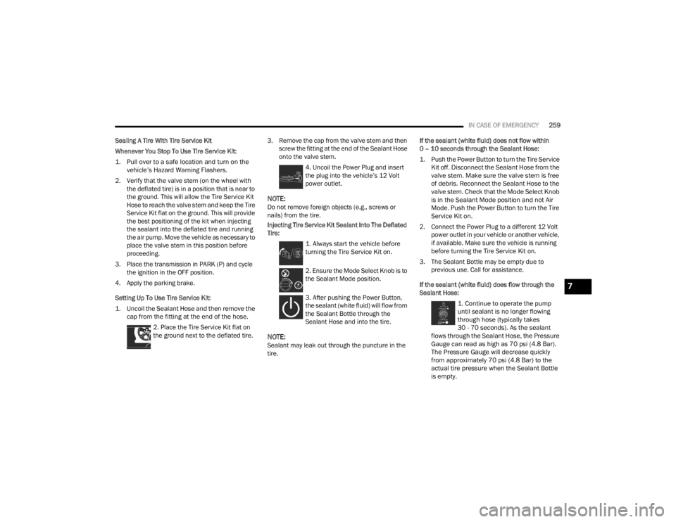
1. Uncoil the Sealant Hose and then remove the cap from the fitting at the end of the hose.
2. Place the Tire Service Kit flat on
the ground next to the deflated tire. 3. Remove the cap from the valve stem and then
screw the fitting at the end of the Sealant Hose
onto the valve stem.
4. Uncoil the Power Plug and insert
the plug into the vehicle’s 12 Volt
power outlet.
NOTE:Do not remove foreign objects (e.g., screws or
nails) from the tire.
Injecting Tire Service Kit Sealant Into The Deflated
Tire:
1. Always start the vehicle before
turning the Tire Service Kit on.
2. Ensure the Mode Select Knob is to
the Sealant Mode position.
3. After pushing the Power Button,
the sealant (white fluid) will flow from
the Sealant Bottle through the
Sealant Hose and into the tire.
NOTE:Sealant may leak out through the puncture in the
tire. If the sealant (white fluid) does not flow within
0 – 10 seconds through the Sealant Hose:
1. Push the Power Button to turn the Tire Service
Kit off. Disconnect the Sealant Hose from the
valve stem. Make sure the valve stem is free
of debris. Reconnect the Sealant Hose to the
valve stem. Check that the Mode Select Knob
is in the Sealant Mode position and not Air
Mode. Push the Power Button to turn the Tire
Service Kit on.
2. Connect the Power Plug to a different 12 Volt power outlet in your vehicle or another vehicle,
if available. Make sure the vehicle is running
before turning the Tire Service Kit on.
3. The Sealant Bottle may be empty due to previous use. Call for assistance.
If the sealant (white fluid) does flow through the
Sealant Hose:
1. Continue to operate the pump
until sealant is no longer flowing
through hose (typically takes
30 - 70 seconds). As the sealant
flows through the Sealant Hose, the Pressure
Gauge can read as high as 70 psi (4.8 Bar).
The Pressure Gauge will decrease quickly
from approximately 70 psi (4.8 Bar) to the
actual tire pressure when the Sealant Bottle
is empty.
7
21_RUV_OM_EN_USC_t.book Page 259