low oil pressure CHRYSLER VOYAGER 2021 Owners Manual
[x] Cancel search | Manufacturer: CHRYSLER, Model Year: 2021, Model line: VOYAGER, Model: CHRYSLER VOYAGER 2021Pages: 348, PDF Size: 18.73 MB
Page 11 of 348
9
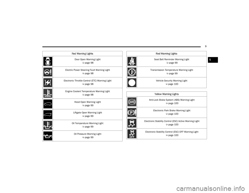
Door Open Warning Light
Úpage 98
Electric Power Steering Fault Warning Light
Úpage 98
Electronic Throttle Control (ETC) Warning Light
Úpage 98
Engine Coolant Temperature Warning Light
Úpage 98
Hood Open Warning Light
Úpage 99
Liftgate Open Warning Light
Úpage 99
Oil Temperature Warning Light
Úpage 99
Oil Pressure Warning Light
Úpage 99
Red Warning Lights
Seat Belt Reminder Warning Light
Úpage 99
Transmission Temperature Warning Light
Úpage 99
Vehicle Security Warning Light
Úpage 100
Yellow Warning Lights
Anti-Lock Brake System (ABS) Warning Light
Úpage 100
Electronic Park Brake Warning Light
Úpage 100
Electronic Stability Control (ESC) Active Warning Light
Úpage 100
Electronic Stability Control (ESC) OFF Warning Light
Úpage 100
Red Warning Lights
1
21_RUV_OM_EN_USC_t.book Page 9
Page 94 of 348
92GETTING TO KNOW YOUR INSTRUMENT PANEL
Coolant Temp
Displays the actual coolant temperature.
Transmission Temp
Displays the actual transmission temperature.
Oil Temp
Displays the actual oil temperature.
Oil Pressure
Displays the actual oil pressure.
Oil Life
Displays the remaining engine oil life as a
percentage.
To reset the Oil Life, you must hold the OK button.
The “Hold OK to Reset” instruction will be
displayed at all times, but the following conditions
will need to be met in order to reset Oil Life:
The ignition must be in the ON/RUN position
If the conditions are met, holding the OK button will
reset the gauge and the numeric display will return
to 100%.
If the conditions are not met, a pop-up message
will display for five seconds, describing the
required conditions, and then the Oil Life screen
will reappear.
Battery Voltage
Displays the actual battery voltage. Engine Hours — If Equipped
Displays the number of hours of engine operation.
Fuel Economy
Push and release the
up or down arrow
button until the Fuel Economy Menu item is
highlighted in the instrument cluster display. The
Fuel Economy Menu will display the following:
Two submenu pages that can be toggled
between using the left and right arrow
buttons; one with Current Value displayed and
one without the Current Value displayed:
Average Fuel Economy
(MPG, L/100 km, or km/L)
Range To Empty (miles or km)
Current Fuel Economy
(MPG, L/100 km, or km/L)
The Max and Min values will correspond to
the particular engine requirements
Hold OK to reset average fuel economy informa -
tion.
Trip Info
Push and release the up or down arrow
button until the Trip Menu item is highlighted in the
instrument cluster display. Push the left or
right arrow button to scroll through the Trip A and Trip B submenus. The Trip information will
display the following:
Distance
Average Fuel Economy
Elapsed Time
Hold the OK button to reset feature information.
Stop / Start – If Equipped
Push and release the up or down arrow
button until the Stop/Start menu title is displayed
in the instrument cluster display.
Audio
Push and release the up or down arrow
button until the Audio Menu displays in the
instrument cluster display.
Messages
Push and release the up or down arrow
button until Messages is highlighted in the
instrument cluster display. This feature shows the
number of stored warning messages. Pushing the
right arrow button will allow you to see what the
stored messages are.
NOTE:The pop-up messages indicate the status of the
system and/or the conditions that need to be met.
Messages remain in the stored stack until
condition is cleared.
21_RUV_OM_EN_USC_t.book Page 92
Page 101 of 348
GETTING TO KNOW YOUR INSTRUMENT PANEL99
If the light turns on while driving, safely pull over
and stop the vehicle. If the Air Conditioning (A/C)
system is on, turn it off. Also, shift the transmission
into NEUTRAL (N) and idle the vehicle. If the
temperature reading does not return to normal,
turn the engine off immediately and call for service
Úpage 265.
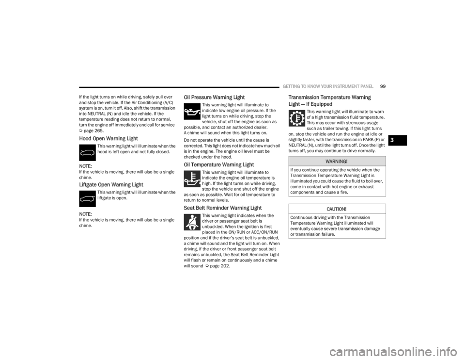
Hood Open Warning Light
This warning light will illuminate when the
hood is left open and not fully closed.
NOTE:If the vehicle is moving, there will also be a single
chime.
Liftgate Open Warning Light
This warning light will illuminate when the
liftgate is open.
NOTE:If the vehicle is moving, there will also be a single
chime.
Oil Pressure Warning Light
This warning light will illuminate to
indicate low engine oil pressure. If the
light turns on while driving, stop the
vehicle, shut off the engine as soon as
possible, and contact an authorized dealer.
A chime will sound when this light turns on.
Do not operate the vehicle until the cause is
corrected. This light does not indicate how much oil
is in the engine. The engine oil level must be
checked under the hood.
Oil Temperature Warning Light
This warning light will illuminate to
indicate the engine oil temperature is
high. If the light turns on while driving,
stop the vehicle and shut off the engine
as soon as possible. Wait for oil temperature to
return to normal levels.
Seat Belt Reminder Warning Light
This warning light indicates when the
driver or passenger seat belt is
unbuckled. When the ignition is first
placed in the ON/RUN or ACC/ON/RUN
position and if the driver’s seat belt is unbuckled,
a chime will sound and the light will turn on. When
driving, if the driver or front passenger seat belt
remains unbuckled, the Seat Belt Reminder Light
will flash or remain on continuously and a chime
will sound
Úpage 202.
Transmission Temperature Warning
Light — If Equipped
This warning light will illuminate to warn
of a high transmission fluid temperature.
This may occur with strenuous usage
such as trailer towing. If this light turns
on, stop the vehicle and run the engine at idle or
slightly faster, with the transmission in PARK (P) or
NEUTRAL (N), until the light turns off. Once the light
turns off, you may continue to drive normally.
WARNING!
If you continue operating the vehicle when the
Transmission Temperature Warning Light is
illuminated you could cause the fluid to boil over,
come in contact with hot engine or exhaust
components and cause a fire.
CAUTION!
Continuous driving with the Transmission
Temperature Warning Light illuminated will
eventually cause severe transmission damage
or transmission failure.
3
21_RUV_OM_EN_USC_t.book Page 99
Page 258 of 348
256IN CASE OF EMERGENCY
Portable Air Compressor Usage With Inflatable
Spare Tire
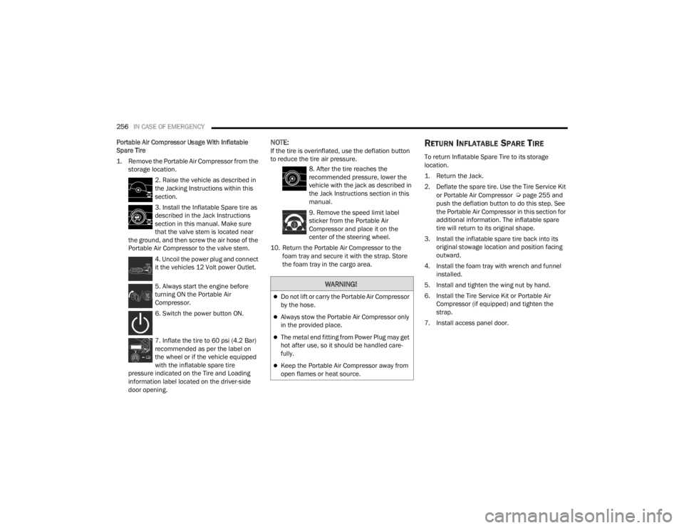
1. Remove the Portable Air Compressor from the storage location.
2. Raise the vehicle as described in
the Jacking Instructions within this
section.
3. Install the Inflatable Spare tire as
described in the Jack Instructions
section in this manual. Make sure
that the valve stem is located near
the ground, and then screw the air hose of the
Portable Air Compressor to the valve stem.
4. Uncoil the power plug and connect
it the vehicles 12 Volt power Outlet.
5. Always start the engine before
turning ON the Portable Air
Compressor.
6. Switch the power button ON.
7. Inflate the tire to 60 psi (4.2 Bar)
recommended as per the label on
the wheel or if the vehicle equipped
with the inflatable spare tire
pressure indicated on the Tire and Loading
information label located on the driver-side
door opening.
NOTE:If the tire is overinflated, use the deflation button
to reduce the tire air pressure.
8. After the tire reaches the
recommended pressure, lower the
vehicle with the jack as described in
the Jack Instructions section in this
manual.
9. Remove the speed limit label
sticker from the Portable Air
Compressor and place it on the
center of the steering wheel.
10. Return the Portable Air Compressor to the foam tray and secure it with the strap. Store
the foam tray in the cargo area.RETURN INFLATABLE SPARE TIRE
To return Inflatable Spare Tire to its storage
location.
1. Return the Jack.
2. Deflate the spare tire. Use the Tire Service Kit
or Portable Air Compressor
Úpage 255 and
push the deflation button to do this step. See
the Portable Air Compressor in this section for
additional information. The inflatable spare
tire will return to its original shape.
3. Install the inflatable spare tire back into its original stowage location and position facing
outward.
4. Install the foam tray with wrench and funnel installed.
5. Install and tighten the wing nut by hand.
6. Install the Tire Service Kit or Portable Air Compressor (if equipped) and tighten the
strap.
7. Install access panel door.
WARNING!
Do not lift or carry the Portable Air Compressor
by the hose.
Always stow the Portable Air Compressor only
in the provided place.
The metal end fitting from Power Plug may get
hot after use, so it should be handled care -
fully.
Keep the Portable Air Compressor away from
open flames or heat source.
21_RUV_OM_EN_USC_t.book Page 256
Page 261 of 348
IN CASE OF EMERGENCY259
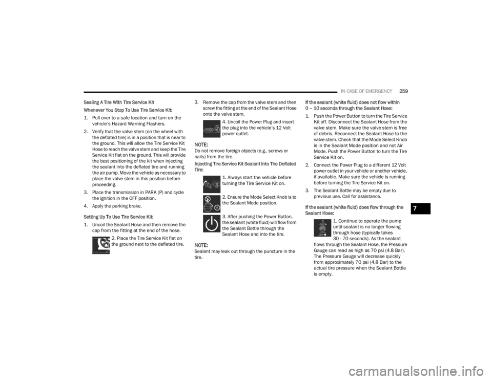
Sealing A Tire With Tire Service Kit
Whenever You Stop To Use Tire Service Kit:
1. Pull over to a safe location and turn on the vehicle’s Hazard Warning Flashers.
2. Verify that the valve stem (on the wheel with the deflated tire) is in a position that is near to
the ground. This will allow the Tire Service Kit
Hose to reach the valve stem and keep the Tire
Service Kit flat on the ground. This will provide
the best positioning of the kit when injecting
the sealant into the deflated tire and running
the air pump. Move the vehicle as necessary to
place the valve stem in this position before
proceeding.
3. Place the transmission in PARK (P) and cycle the ignition in the OFF position.
4. Apply the parking brake.
Setting Up To Use Tire Service Kit:
1. Uncoil the Sealant Hose and then remove the cap from the fitting at the end of the hose.
2. Place the Tire Service Kit flat on
the ground next to the deflated tire. 3. Remove the cap from the valve stem and then
screw the fitting at the end of the Sealant Hose
onto the valve stem.
4. Uncoil the Power Plug and insert
the plug into the vehicle’s 12 Volt
power outlet.
NOTE:Do not remove foreign objects (e.g., screws or
nails) from the tire.
Injecting Tire Service Kit Sealant Into The Deflated
Tire:
1. Always start the vehicle before
turning the Tire Service Kit on.
2. Ensure the Mode Select Knob is to
the Sealant Mode position.
3. After pushing the Power Button,
the sealant (white fluid) will flow from
the Sealant Bottle through the
Sealant Hose and into the tire.
NOTE:Sealant may leak out through the puncture in the
tire. If the sealant (white fluid) does not flow within
0 – 10 seconds through the Sealant Hose:
1. Push the Power Button to turn the Tire Service
Kit off. Disconnect the Sealant Hose from the
valve stem. Make sure the valve stem is free
of debris. Reconnect the Sealant Hose to the
valve stem. Check that the Mode Select Knob
is in the Sealant Mode position and not Air
Mode. Push the Power Button to turn the Tire
Service Kit on.
2. Connect the Power Plug to a different 12 Volt power outlet in your vehicle or another vehicle,
if available. Make sure the vehicle is running
before turning the Tire Service Kit on.
3. The Sealant Bottle may be empty due to previous use. Call for assistance.
If the sealant (white fluid) does flow through the
Sealant Hose:
1. Continue to operate the pump
until sealant is no longer flowing
through hose (typically takes
30 - 70 seconds). As the sealant
flows through the Sealant Hose, the Pressure
Gauge can read as high as 70 psi (4.8 Bar).
The Pressure Gauge will decrease quickly
from approximately 70 psi (4.8 Bar) to the
actual tire pressure when the Sealant Bottle
is empty.
7
21_RUV_OM_EN_USC_t.book Page 259
Page 262 of 348
260IN CASE OF EMERGENCY
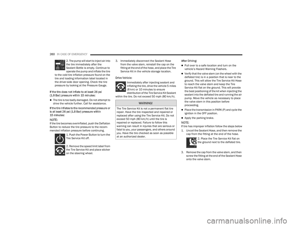
2. The pump will start to inject air into
the tire immediately after the
Sealant Bottle is empty. Continue to
operate the pump and inflate the tire
to the cold tire inflation pressure found on the
tire and loading information label located in
the driver-side door opening. Check the tire
pressure by looking at the Pressure Gauge.
If the tire does not inflate to at least 26 psi
(1.8 Bar) pressure within 15 minutes:
The tire is too badly damaged. Do not attempt to
drive the vehicle further. Call for assistance.
If the tire inflates to the recommended pressure or
is at least 26 psi (1.8 Bar) pressure within
15 minutes:
NOTE:If the tire becomes overinflated, push the Deflation
Button to reduce the tire pressure to the recom -
mended inflation pressure before continuing.
1. Push the Power Button to turn the
Tire Service Kit off.
2. Remove the speed limit label from
the Tire Service Kit and place sticker
on the steering wheel. 3. Immediately disconnect the Sealant Hose
from the valve stem, reinstall the cap on the
fitting at the end of the hose, and place the Tire
Service Kit in the vehicle storage location.
Drive Vehicle: Immediately after injecting sealant and
inflating the tire, drive the vehicle 5 miles
(8 km) or 10 minutes to ensure distribution of the Tire Service Kit Sealant
within the tire. Do not exceed 50 mph (80 km/h). After Driving:
Pull over to a safe location and turn on the
vehicle’s Hazard Warning Flashers.
Verify that the valve stem (on the wheel with the
deflated tire) is in a position that is near to the
ground. This will allow the Tire Service Kit Hose
to reach the valve stem and keep the Tire
Service Kit flat on the ground. This will provide
the best positioning of the kit when injecting the
sealant into the deflated tire and running the air
pump. Move the vehicle as necessary to place
the valve stem in this position before
proceeding.
Place the transmission in PARK (P) and cycle the
ignition in the OFF position.
Apply the parking brake.
NOTE:If tire has improper inflation follow the steps below
1. Uncoil the Sealant Hose, and then remove the
cap from the fitting at the end of the hose.
2. Place the Tire Service Kit flat on
the ground next to the deflated tire.
3. Remove the cap from the valve stem, and then screw the fitting at the end of the Sealant Hose
onto the valve stem.
WARNING!
The Tire Service Kit is not a permanent flat tire
repair. Have the tire inspected and repaired or
replaced after using the Tire Service Kit. Do not
exceed 50 mph (80 km/h) until the tire is
repaired or replaced. Failure to follow this
warning can result in injuries that are serious or
fatal to you, your passengers, and others around
you. Have the tire checked as soon as possible
at an authorized dealer.
21_RUV_OM_EN_USC_t.book Page 260
Page 278 of 348
276SERVICING AND MAINTENANCE
(Continued)
CHECKING OIL LEVEL
To ensure proper engine lubrication, the engine oil
must be maintained at the correct level. Check the
oil level at regular intervals, such as every fuel
stop. The best time to check the engine oil level is
about five minutes after a fully warmed up engine
is shut off.
Checking the oil while the vehicle is on level ground
will improve the accuracy of the oil level readings.
There are four possible dipstick types:
Crosshatched zone.
Crosshatched zone marked SAFE.
Crosshatched zone marked with MIN at the low
end of the range and MAX at the high end of the
range.
Crosshatched zone marked with dimples at the
MIN and the MAX ends of the range.
NOTE:Always maintain the oil level within the crosshatch
markings on the dipstick.
Adding 1 quart (1 liter) of oil when the reading is at
the low end of the dipstick range will raise the oil
level to the high end of the range marking.
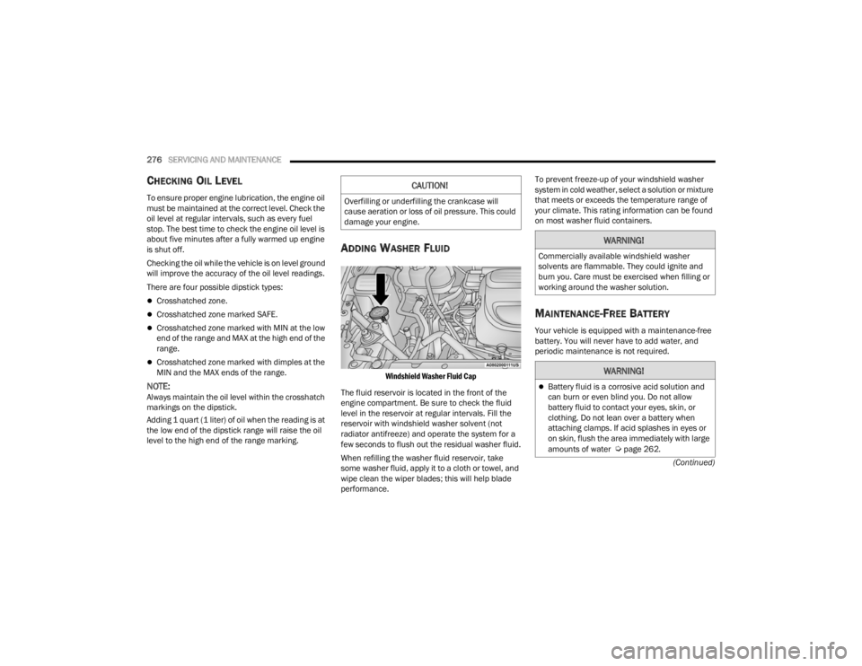
ADDING WASHER FLUID
Windshield Washer Fluid Cap
The fluid reservoir is located in the front of the
engine compartment. Be sure to check the fluid
level in the reservoir at regular intervals. Fill the
reservoir with windshield washer solvent (not
radiator antifreeze) and operate the system for a
few seconds to flush out the residual washer fluid.
When refilling the washer fluid reservoir, take
some washer fluid, apply it to a cloth or towel, and
wipe clean the wiper blades; this will help blade
performance. To prevent freeze-up of your windshield washer
system in cold weather, select a solution or mixture
that meets or exceeds the temperature range of
your climate. This rating information can be found
on most washer fluid containers.
MAINTENANCE-FREE BATTERY
Your vehicle is equipped with a maintenance-free
battery. You will never have to add water, and
periodic maintenance is not required.
CAUTION!
Overfilling or underfilling the crankcase will
cause aeration or loss of oil pressure. This could
damage your engine.
WARNING!
Commercially available windshield washer
solvents are flammable. They could ignite and
burn you. Care must be exercised when filling or
working around the washer solution.
WARNING!
Battery fluid is a corrosive acid solution and
can burn or even blind you. Do not allow
battery fluid to contact your eyes, skin, or
clothing. Do not lean over a battery when
attaching clamps. If acid splashes in eyes or
on skin, flush the area immediately with large
amounts of water
Úpage 262.
21_RUV_OM_EN_USC_t.book Page 276
Page 279 of 348
SERVICING AND MAINTENANCE277
PRESSURE WASHING
Cleaning the engine compartment with a high
pressure washer is not recommended.
VEHICLE MAINTENANCE
An authorized dealer has the qualified service
personnel, special tools, and equipment to
perform all service operations in an expert
manner. Service Manuals are available which
include detailed service information for your
vehicle. Refer to these Service Manuals before
attempting any procedure yourself.
NOTE:Intentional tampering with emissions control
systems may void your warranty and could result in
civil penalties being assessed against you.
ENGINE OIL
Engine Oil Selection
For best performance and maximum protection
under all types of operating conditions, the
manufacturer only recommends engine oils that
are API Certified and meet the requirements of the
manufacturer Material Standard MS-6395.
Battery gas is flammable and explosive. Keep
flame or sparks away from the battery. Do not
use a booster battery or any other booster
source with an output greater than 12 Volts.
Do not allow cable clamps to touch each
other.
Battery posts, terminals, and related accesso -
ries contain lead and lead compounds. Wash
hands after handling.
CAUTION!
It is essential when replacing the cables on
the battery that the positive cable is attached
to the positive post and the negative cable is
attached to the negative post. Battery posts
are marked positive (+) and negative (-) and
are identified on the battery case. Cable
clamps should be tight on the terminal posts
and free of corrosion.
If a “fast charger” is used while the battery is
in the vehicle, disconnect both vehicle battery
cables before connecting the charger to the
battery. Do not use a “fast charger” to provide
starting voltage.
WARNING!
CAUTION!
Precautions have been taken to safeguard all
parts and connections however, the pressures
generated by these machines is such that
complete protection against water ingress
cannot be guaranteed.
WARNING!
You can be badly injured working on or around a
motor vehicle. Only do service work for which
you have the knowledge and the proper
equipment. If you have any doubt about your
ability to perform a service job, take your vehicle
to a competent mechanic.
8
21_RUV_OM_EN_USC_t.book Page 277
Page 282 of 348
280SERVICING AND MAINTENANCE
Refrigerant Recovery And Recycling —
R–1234yf
R–1234yf Air Conditioning Refrigerant is a
hydrofluoroolefin (HFO) that is endorsed by the
Environmental Protection Agency and is an
ozone-friendly substance with a low
global-warming potential. It is recommended that
air conditioning service be performed by an
authorized dealer using recovery and recycling
equipment.
NOTE:Use only manufacturer approved A/C system PAG
compressor oil, and refrigerants.
Cabin Air Filter
The cabin air filter is located in the fresh air inlet
behind the glove compartment. Perform the
following procedure to replace the filter:
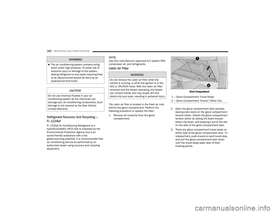
1. Remove all contents from the glove
compartment.
Glove Compartment
2. Open the glove compartment door partially, leaving extra slack on the glove compartment
tension tether. Detach the glove compartment
tension tether by sliding the black tension
tether clip down, and popping it out of the slot
on the side of the glove compartment door.
3. There are glove compartment travel stops on either side of the glove compartment door. To
release them, push inward on each travel stop,
and pull the glove compartment door down
until the travel stops pass clear of their
hooking points.
The air conditioning system contains refrig -
erant under high pressure. To avoid risk of
personal injury or damage to the system,
adding refrigerant or any repair requiring lines
to be disconnected should be done by an
experienced technician.
CAUTION!
Do not use chemical flushes in your air
conditioning system as the chemicals can
damage your air conditioning components. Such
damage is not covered by the New Vehicle
Limited Warranty.
WARNING!
WARNING!
Do not remove the cabin air filter while the
vehicle is running, or while the ignition is in the
ACC or ON/RUN mode. With the cabin air filter
removed and the blower operating, the blower
can contact hands and may propel dirt and
debris into your eyes, resulting in personal injury.
1 — Glove Compartment Travel Stops
2 — Glove Compartment Tension Tether Clip
21_RUV_OM_EN_USC_t.book Page 280
Page 314 of 348
312SERVICING AND MAINTENANCE
Life Of Tire
The service life of a tire is dependent upon varying
factors including, but not limited to:
Driving style.
Tire pressure - Improper cold tire inflation pres -
sures can cause uneven wear patterns to
develop across the tire tread. These abnormal
wear patterns will reduce tread life, resulting in
the need for earlier tire replacement.
Distance driven.
Performance tires, tires with a speed rating of V
or higher, and Summer tires typically have a
reduced tread life. Rotation of these tires per
the vehicle scheduled maintenance is highly
recommended.
NOTE:Wheel valve stem must be replaced as well when
installing new tires due to wear and tear in existing
tires. Keep dismounted tires in a cool, dry place with as
little exposure to light as possible. Protect tires
from contact with oil, grease, and gasoline.
Replacement Tires
The tires on your new vehicle provide a balance of
many characteristics. They should be inspected
regularly for wear and correct cold tire inflation
pressures. The manufacturer strongly
recommends that you use tires equivalent to the
originals in size, quality and performance when
replacement is needed
Úpage 311. The Load
Index and Speed Symbol for your tire will be found
on the original equipment tire sidewall.
See the Tire Sizing Chart example found in the Tire
Safety Information section of this manual for more
information relating to the Load Index and Speed
Symbol of a tire
Úpage 303.
It is recommended to replace the two front tires or
two rear tires as a pair. Replacing just one tire can
seriously affect your vehicle’s handling. If you ever
replace a wheel, make sure that the wheel’s
specifications match those of the original wheels.
It is recommended you contact an authorized tire
dealer or original equipment dealer with any
questions you may have on tire specifications or
capability. Failure to use equivalent replacement
tires may adversely affect the safety, handling, and
ride of your vehicle.WARNING!
Tires and the spare tire should be replaced after
six years, regardless of the remaining tread.
Failure to follow this warning can result in
sudden tire failure. You could lose control and
have a collision resulting in serious injury or
death.
WARNING!
Do not use a tire, wheel size, load rating, or
speed rating other than that specified for your
vehicle. Some combinations of unapproved
tires and wheels may change suspension
dimensions and performance characteristics,
resulting in changes to steering, handling, and
braking of your vehicle. This can cause unpre -
dictable handling and stress to steering and
suspension components. You could lose
control and have a collision resulting in
serious injury or death. Use only the tire and
wheel sizes with load ratings approved for
your vehicle.
Never use a tire with a smaller load index or
capacity, other than what was originally
equipped on your vehicle. Using a tire with a
smaller load index could result in tire over -
loading and failure. You could lose control and
have a collision.
Failure to equip your vehicle with tires having
adequate speed capability can result in
sudden tire failure and loss of vehicle control.
21_RUV_OM_EN_USC_t.book Page 312