Lock CHRYSLER VOYAGER 2022 Manual Online
[x] Cancel search | Manufacturer: CHRYSLER, Model Year: 2022, Model line: VOYAGER, Model: CHRYSLER VOYAGER 2022Pages: 316, PDF Size: 17.41 MB
Page 212 of 316

210SAFETY
Installing A Child Restraint With A
Switchable Automatic Locking Retractor
(ALR):
Child restraint systems are designed to be secured
in vehicle seats by lap belts or the lap belt portion
of a lap/shoulder belt.
1. Place the child seat in the center of the
seating position. If the second row seat can
be reclined, you may recline the seat and/or
raise the head restraint (if adjustable) to get a
better fit. If the rear seat can be moved
forward and rearward in the vehicle, you may
wish to move it to its rear-most position to
make room for the child seat. You may also
move the front seat forward to allow more
room for the child seat.
2. Pull enough of the seat belt webbing from the
retractor to pass it through the belt path of the
child restraint. Do not twist the belt webbing in
the belt path.
3. Slide the latch plate into the buckle until you hear a “click.”
4. Pull on the webbing to make the lap portion tight against the child seat.
5. To lock the seat belt, pull down on the shoulder part of the belt until you have pulled all the
seat belt webbing out of the retractor. Then,
allow the webbing to retract back into the
retractor. As the webbing retracts, you will hear
a clicking sound. This means the seat belt is
now in the Automatic Locking mode.
6. Try to pull the webbing out of the retractor. If it is locked, you should not be able to pull out any
webbing. If the retractor is not
locked, repeat
step 5.
7. Finally, pull up on any excess webbing to tighten the lap portion around the child
restraint while you push the child restraint
rearward and downward into the vehicle seat. 8. If the child restraint has a top tether strap and
the seating position has a top tether
anchorage, connect the tether strap to the
anchorage and tighten the tether strap. See
Úpage 211 for directions to attach a tether
anchor.
9. Test that the child restraint is installed tightly by pulling back and forth on the child seat at
the belt path. It should not move more than
1 inch (25.4 mm) in any direction.
Any seat belt system will loosen with time, so check
the belt occasionally, and pull it tight if necessary.
Seat Belt Park Stitch — If Equipped
The rear outboard seat belts may be equipped with
a park stitch to raise the latch plate for easier
access to occupants. If the park stitch interferes
with the tight installation of a child restraint, slide
the latch plate over the stitching to shorten the lap
portion of the belt and install the car seat following
the steps above. When the car seat is removed
from the vehicle, slide the latch plate above the
park stitch to enable occupants to latch the
seatbelt securely.
WARNING!
Improper installation or failure to properly
secure a child restraint can lead to failure of
the restraint. The child could be badly injured
or killed.
Follow the child restraint manufacturer’s
directions exactly when installing an infant or
child restraint.
22_RUVG_OM_EN_USC_t.book Page 210
Page 213 of 316

SAFETY211
Seat Belt Park Stitch Location
If the park stitch interferes with the lock-off
features of the child restraint, do not use the
lock-off feature. Instead, switch the seat belt to the
locking mode, as described in the steps above or
move the car seat to a different seating position.
Seat Belt Park Stitch
Installing Child Restraints Using the Top
Tether Anchorage
1. Look behind the seating position where you plan to install the child restraint to find the
tether anchorage. You may need to move the
seat forward to provide better access to the
tether anchorage. If there is no top tether
anchorage for that seating position, move the
child restraint to another position in the
vehicle if one is available.
Top Tether Anchorage Locations — 2nd Row Bench
WARNING!
Do not attach a tether strap for a rear-facing car
seat to any location in front of the car seat,
including the seat frame or a tether anchorage.
Only attach the tether strap of a rear-facing car
seat to the tether anchorage that is approved for
that seating position, located behind the top of
the vehicle seat. See
Úpage 201 for the
location of approved tether anchorages in your
vehicle.
6
22_RUVG_OM_EN_USC_t.book Page 211
Page 217 of 316
SAFETY215
(Continued)
PERIODIC SAFETY CHECKS YOU SHOULD
M
AKE OUTSIDE THE VEHICLE
Tires
Examine tires for excessive tread wear and uneven
wear patterns. Check for stones, nails, glass, or
other objects lodged in the tread or sidewall.
Inspect the tread for cuts and cracks. Inspect
sidewalls for cuts, cracks, and bulges. Check the
lug nut/bolt torque for tightness. Check the tires
(including spare) for proper cold inflation pressure.
Lights
Have someone observe the operation of brake
lights and exterior lights while you work the
controls. Check turn signal and high beam
indicator lights on the instrument panel.
Door Latches
Check for proper closing, latching, and locking.
Fluid Leaks
Check area under the vehicle after overnight
parking for fuel, coolant, oil, or other fluid leaks.
Also, if gasoline fumes are detected or if fuel or
brake fluid leaks are suspected, the cause should
be located and corrected immediately.
ALWAYS REMOVE THE EXISTING
FLOOR MAT FROM THE VEHICLE
before installing any other floor mat.
NEVER install or stack an additional
floor mat on top of an existing floor mat.
ONLY install floor mats designed to fit your
vehicle. NEVER install a floor mat that cannot
be properly attached and secured to your
vehicle. If a floor mat needs to be replaced,
only use a FCA approved floor mat for the
specific make, model, and year of your
vehicle.
ONLY use the driver’s side floor mat on the
driver’s side floor area. To check for interfer -
ence, with the vehicle properly parked with the
engine off, fully depress the accelerator, the
brake, and the clutch pedal (if present) to
check for interference. If your floor mat inter -
feres with the operation of any pedal, or is not
secure to the floor, remove the floor mat from
the vehicle and place the floor mat in your
trunk.
ONLY use the passenger’s side floor mat on
the passenger’s side floor area.
WARNING!
ALWAYS make sure objects cannot fall or slide
into the driver’s side floor area when the
vehicle is moving. Objects can become
trapped under accelerator, brake, or clutch
pedals and could cause a loss of vehicle
control.
NEVER place any objects under the floor mat
(e.g., towels, keys, etc.). These objects could
change the position of the floor mat and may
cause interference with the accelerator,
brake, or clutch pedals.
If the vehicle carpet has been removed and
re-installed, always properly attach carpet to
the floor and check the floor mat fasteners are
secure to the vehicle carpet. Fully depress
each pedal to check for interference with the
accelerator, brake, or clutch pedals then
re-install the floor mats.
It is recommended to only use mild soap and
water to clean your floor mats. After cleaning,
always check your floor mat has been properly
installed and is secured to your vehicle using
the floor mat fasteners by lightly pulling mat.
WARNING!
6
22_RUVG_OM_EN_USC_t.book Page 215
Page 223 of 316
IN CASE OF EMERGENCY221
PREPARATIONS FOR JACKING
1. Park the vehicle on a firm, level surface. Avoid
ice or slippery areas.
2. Turn on the Hazard Warning Flashers.
3. Apply the parking brake.
4. Place the gear selector into PARK (P).
5. Place the ignition in OFF mode.
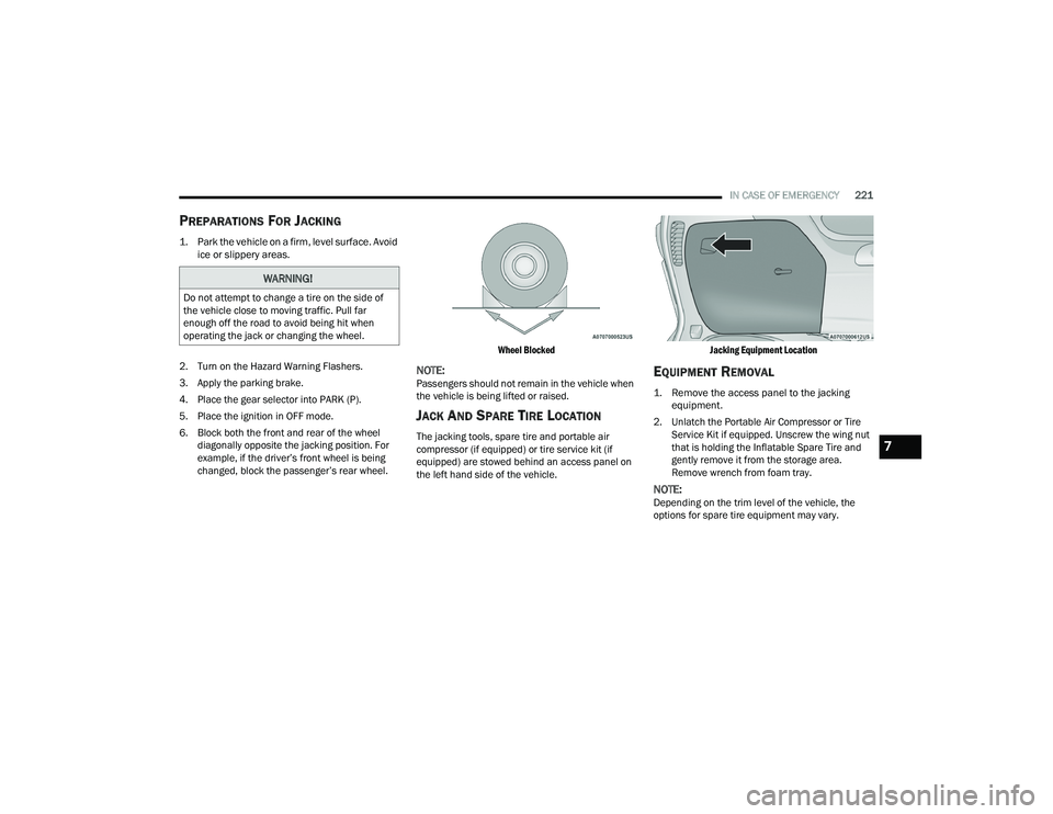
6. Block both the front and rear of the wheel diagonally opposite the jacking position. For
example, if the driver’s front wheel is being
changed, block the passenger’s rear wheel.
Wheel Blocked
NOTE:Passengers should not remain in the vehicle when
the vehicle is being lifted or raised.
JACK AND SPARE TIRE LOCATION
The jacking tools, spare tire and portable air
compressor (if equipped) or tire service kit (if
equipped) are stowed behind an access panel on
the left hand side of the vehicle.
Jacking Equipment Location
EQUIPMENT REMOVAL
1. Remove the access panel to the jacking
equipment.
2. Unlatch the Portable Air Compressor or Tire Service Kit if equipped. Unscrew the wing nut
that is holding the Inflatable Spare Tire and
gently remove it from the storage area.
Remove wrench from foam tray.
NOTE:Depending on the trim level of the vehicle, the
options for spare tire equipment may vary.
WARNING!
Do not attempt to change a tire on the side of
the vehicle close to moving traffic. Pull far
enough off the road to avoid being hit when
operating the jack or changing the wheel.
7
22_RUVG_OM_EN_USC_t.book Page 221
Page 224 of 316
222IN CASE OF EMERGENCY
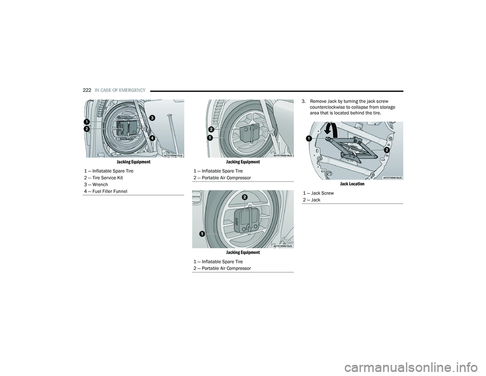
Jacking Equipment Jacking Equipment
Jacking Equipment
3. Remove Jack by turning the jack screw
counterclockwise to collapse from storage
area that is located behind the tire.
Jack Location
1 — Inflatable Spare Tire
2 — Tire Service Kit
3 — Wrench
4 — Fuel Filler Funnel
1 — Inflatable Spare Tire
2 — Portable Air Compressor
1 — Inflatable Spare Tire
2 — Portable Air Compressor
1 — Jack Screw
2 — Jack
22_RUVG_OM_EN_USC_t.book Page 222
Page 225 of 316
IN CASE OF EMERGENCY223
JACKING INSTRUCTIONS
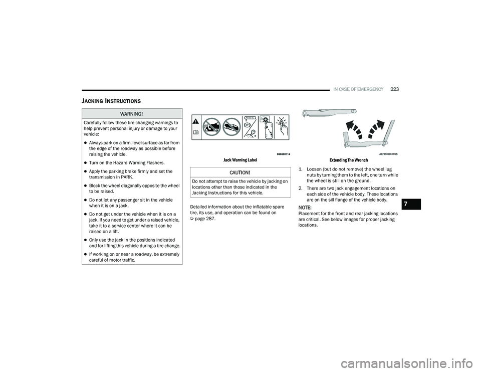
Jack Warning Label
Detailed information about the inflatable spare
tire, its use, and operation can be found on
Úpage 287.
Extending The Wrench
1. Loosen (but do not remove) the wheel lug nuts by turning them to the left, one turn while
the wheel is still on the ground.
2. There are two jack engagement locations on each side of the vehicle body. These locations
are on the sill flange of the vehicle body.
NOTE:Placement for the front and rear jacking locations
are critical. See below images for proper jacking
locations.
WARNING!
Carefully follow these tire changing warnings to
help prevent personal injury or damage to your
vehicle:
Always park on a firm, level surface as far from
the edge of the roadway as possible before
raising the vehicle.
Turn on the Hazard Warning Flashers.
Apply the parking brake firmly and set the
transmission in PARK.
Block the wheel diagonally opposite the wheel
to be raised.
Do not let any passenger sit in the vehicle
when it is on a jack.
Do not get under the vehicle when it is on a
jack. If you need to get under a raised vehicle,
take it to a service center where it can be
raised on a lift.
Only use the jack in the positions indicated
and for lifting this vehicle during a tire change.
If working on or near a roadway, be extremely
careful of motor traffic.
CAUTION!
Do not attempt to raise the vehicle by jacking on
locations other than those indicated in the
Jacking Instructions for this vehicle.
7
22_RUVG_OM_EN_USC_t.book Page 223
Page 227 of 316
IN CASE OF EMERGENCY225
3. Place the wrench on the jack screw and turn clockwise until the jack head is properly
engaged in the described location. Do not
raise the vehicle until you are sure the jack is
securely engaged.
4. Raise the vehicle by turning the jack screw clockwise, using the swivel wrench. Raise the
vehicle only until the tire just clears the surface
and enough clearance is obtained to install the
compact spare tire. Minimum tire lift provides
maximum stability.
5. Remove the wheel lug nuts, for vehicles with wheel covers, remove the cover from the
wheel by hand. Do not pry the wheel cover off.
Then pull the wheel off the hub.
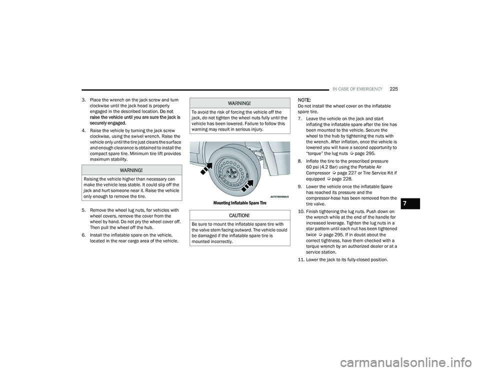
6. Install the inflatable spare on the vehicle, located in the rear cargo area of the vehicle.
Mounting Inflatable Spare Tire
NOTE:Do not install the wheel cover on the inflatable
spare tire.
7. Leave the vehicle on the jack and start
inflating the inflatable spare after the tire has
been mounted to the vehicle. Secure the
wheel to the hub by tightening the nuts with
the wrench. After inflation, once the vehicle is
lowered you will have a second opportunity to
“torque” the lug nuts
Úpage 295.
8. Inflate the tire to the prescribed pressure 60 psi (4.2 Bar) using the Portable Air
Compressor
Úpage 227 or Tire Service Kit if
equipped Úpage 228.
9. Lower the vehicle once the inflatable Spare has reached its pressure and the
compressor-hose has been removed from the
tire valve.
10. Finish tightening the lug nuts. Push down on the wrench while at the end of the handle for
increased leverage. Tighten the lug nuts in a
star pattern until each nut has been tightened
twice
Úpage 295. If in doubt about the
correct tightness, have them checked with a
torque wrench by an authorized dealer or at a
service station.
11. Lower the jack to its fully-closed position.
WARNING!
Raising the vehicle higher than necessary can
make the vehicle less stable. It could slip off the
jack and hurt someone near it. Raise the vehicle
only enough to remove the tire.
WARNING!
To avoid the risk of forcing the vehicle off the
jack, do not tighten the wheel nuts fully until the
vehicle has been lowered. Failure to follow this
warning may result in serious injury.
CAUTION!
Be sure to mount the inflatable spare tire with
the valve stem facing outward. The vehicle could
be damaged if the inflatable spare tire is
mounted incorrectly.
7
22_RUVG_OM_EN_USC_t.book Page 225
Page 228 of 316

226IN CASE OF EMERGENCY
12. Place the deflated (flat) tire and foam tray cover assembly in the rear cargo area. Do not
stow the deflated tire in the inflatable spare
tire location. Have the full-sized tire repaired or
replaced, as soon as possible.
13. Stow the jack back in the stowage compartment and place the access panel
back. The stud of the storage area must be
threaded through the lower part of the jack.
Then turn the Jack Screw clockwise to secure
it in place.
NOTE:Stow the foam tray and components in the cargo
area.
Storing The Jack
ROAD TIRE INSTALLATION
Vehicles Equipped With Wheel Covers
1. Mount the road tire on the axle.
2. To ease the installation process for steel
wheels with wheel covers, install two lug nuts
on the mounting studs which are on each side
of the valve stem. Install the lug nuts with the
cone shaped end of the nut toward the wheel.
Lightly tighten the lug nuts.
Tire And Wheel Cover Or Center Cap
3. Align the valve notch in the wheel cover with the valve stem on the wheel. Install the cover
by hand, snapping the cover over the two lug
nuts. Do not use a hammer or excessive force
to install the cover.
WARNING!
A loose tire or jack thrown forward in a collision
or hard stop could endanger the occupants of
the vehicle. Always stow the jack parts and the
spare tire in the places provided. Have the
deflated (flat) tire repaired or replaced
immediately.
1 — Jack Screw
2 — Jack
3 — Stud1 — Valve Stem
2 — Valve Notch
3 — Road Tire
4 — Wheel Cover
5 — Wheel Lug Nut
22_RUVG_OM_EN_USC_t.book Page 226
Page 229 of 316
IN CASE OF EMERGENCY227
4. Install the remaining lug nuts with the cone shaped end of the nut toward the wheel.
Lightly tighten all the lug nuts until the wheel
sits flush onto the hub and there is no play. The
nuts will have to be fully tightened once the
vehicle is lowered. Tightening an improperly
seated wheel under vehicle load can damage
the threads, cause vibration, and undermine
safety.
5. Lower the vehicle to the ground by turning the jack handle counterclockwise.
6. Finish tightening the lug nuts. Push down on the wrench while at the end of the handle for
increased leverage. Tighten the lug nuts in a
star pattern until each nut has been tightened
twice. Details for proper wheel lug nut torque
Úpage 295. If in doubt about the correct
tightness, have them checked with a torque
wrench by an authorized dealer or at a service
station. 7. After 25 miles (40 km) check the lug nut
torque with a torque wrench to ensure that all
lug nuts are properly seated against the wheel.
PORTABLE AIR COMPRESSOR —
I
F EQUIPPED
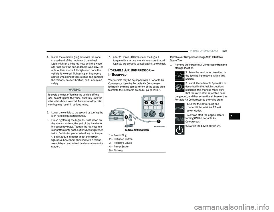
Your vehicle may be equipped with a Portable Air
Compressor. Use the Portable Air Compressor
located in the side compartment of the cargo area
to inflate the inflatable tire to 60 psi (4.2 Bar).
Portable Air Compressor
Portable Air Compressor Usage With Inflatable
Spare Tire
1. Remove the Portable Air Compressor from the
storage location.
2. Raise the vehicle as described in
the Jacking Instructions within this
section.
3. Install the Inflatable Spare tire as
described in the Jack Instructions
section in this manual. Make sure
that the valve stem is located near
the ground, and then screw the air hose of the
Portable Air Compressor to the valve stem.
4. Uncoil the power plug and
connect it the vehicles 12 Volt
power Outlet.
5. Always start the engine before
turning ON the Portable Air
Compressor.
6. Switch the power button ON.
WARNING!
To avoid the risk of forcing the vehicle off the
jack, do not tighten the wheel nuts fully until the
vehicle has been lowered. Failure to follow this
warning may result in serious injury.
1 — Power Plug
2 — Deflation Button
3 — Pressure Gauge
4 — Power Button
5 — Air Hose
7
22_RUVG_OM_EN_USC_t.book Page 227
Page 240 of 316
238IN CASE OF EMERGENCY
MANUAL PARK RELEASE
To move the vehicle in cases where the
transmission will not shift out of PARK (P) (such as
a depleted battery), a Manual Park Release is
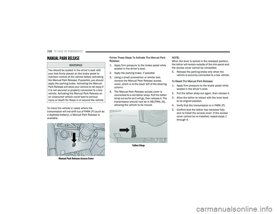
available.
Manual Park Release Access Cover
Follow These Steps To Activate The Manual Park
Release:
1. Apply firm pressure to the brake pedal while
seated in the driver’s seat.
2. Apply the parking brake, if possible.
3. Using a small screwdriver or similar tool, remove the Manual Park Release access
cover, which is to the lower left of the steering
column.
4. The Manual Park Release access cover is connected to a red tether strap. Pull the tether
strap out as far as it will go, then release it. The
transmission should now be in NEUTRAL (N),
allowing the vehicle to be moved.
Tether Strap
NOTE:When the lever is locked in the released position,
the tether will remain outside of the trim panel and
the access cover cannot be reinstalled.
5. Release the parking brake only when the vehicle is securely connected to a tow vehicle.
To Reset The Manual Park Release:
1. Apply firm pressure to the brake pedal while seated in the driver’s seat.
2. Pull the tether strap out again, then release it.
3. Allow the tether to retract with the lever back to its original position.
4. Verify that the transmission is in PARK (P).
5. Confirm that the tether has retracted fully and re-install the access cover. If the access
cover cannot be re-installed, repeat steps 1
through 4.
WARNING!
You should be seated in the driver’s seat with
your foot firmly placed on the brake pedal to
maintain control of the vehicle before activating
the Manual Park Release. If possible, you should
apply the parking brake. Activating the Manual
Park Release will allow your vehicle to roll away if
it is not secured or properly connected to a tow
vehicle. Activating the Manual Park Release on
an unsecured vehicle could lead to serious
injury or death for those in or around the vehicle.
22_RUVG_OM_EN_USC_t.book Page 238