Tire service CHRYSLER VOYAGER 2023 Owner's Manual
[x] Cancel search | Manufacturer: CHRYSLER, Model Year: 2023, Model line: VOYAGER, Model: CHRYSLER VOYAGER 2023Pages: 256, PDF Size: 13.97 MB
Page 185 of 256
IN CASE OF EMERGENCY183
If the sealant (white fluid) does flow through the
Sealant Hose:
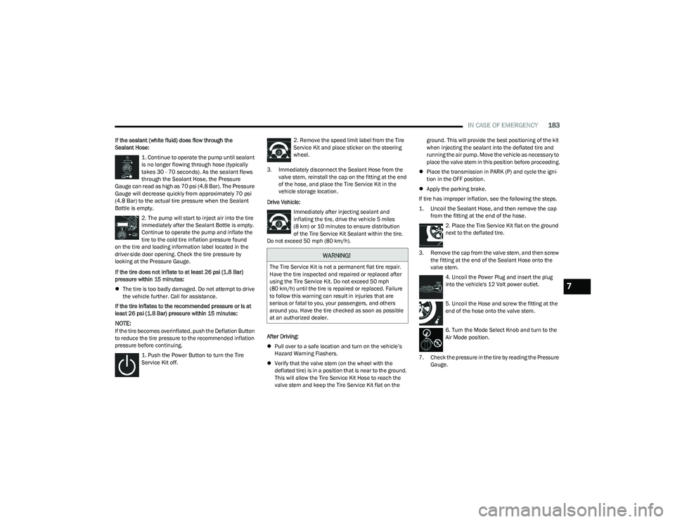
1. Continue to operate the pump until sealant
is no longer flowing through hose (typically
takes 30 - 70 seconds). As the sealant flows
through the Sealant Hose, the Pressure
Gauge can read as high as 70 psi (4.8 Bar). The Pressure
Gauge will decrease quickly from approximately 70 psi
(4.8 Bar) to the actual tire pressure when the Sealant
Bottle is empty.
2. The pump will start to inject air into the tire
immediately after the Sealant Bottle is empty.
Continue to operate the pump and inflate the
tire to the cold tire inflation pressure found
on the tire and loading information label located in the
driver-side door opening. Check the tire pressure by
looking at the Pressure Gauge.
If the tire does not inflate to at least 26 psi (1.8 Bar)
pressure within 15 minutes:
The tire is too badly damaged. Do not attempt to drive
the vehicle further. Call for assistance.
If the tire inflates to the recommended pressure or is at
least 26 psi (1.8 Bar) pressure within 15 minutes:
NOTE:If the tire becomes overinflated, push the Deflation Button
to reduce the tire pressure to the recommended inflation
pressure before continuing.
1. Push the Power Button to turn the Tire
Service Kit off.
2. Remove the speed limit label from the Tire
Service Kit and place sticker on the steering
wheel.
3. Immediately disconnect the Sealant Hose from the valve stem, reinstall the cap on the fitting at the end
of the hose, and place the Tire Service Kit in the
vehicle storage location.
Drive Vehicle: Immediately after injecting sealant and
inflating the tire, drive the vehicle 5 miles
(8 km) or 10 minutes to ensure distribution
of the Tire Service Kit Sealant within the tire.
Do not exceed 50 mph (80 km/h).
After Driving:
Pull over to a safe location and turn on the vehicle’s
Hazard Warning Flashers.
Verify that the valve stem (on the wheel with the
deflated tire) is in a position that is near to the ground.
This will allow the Tire Service Kit Hose to reach the
valve stem and keep the Tire Service Kit flat on the ground. This will provide the best positioning of the kit
when injecting the sealant into the deflated tire and
running the air pump. Move the vehicle as necessary to
place the valve stem in this position before proceeding.
Place the transmission in PARK (P) and cycle the igni -
tion in the OFF position.
Apply the parking brake.
If tire has improper inflation, see the following the steps.
1. Uncoil the Sealant Hose, and then remove the cap from the fitting at the end of the hose.
2. Place the Tire Service Kit flat on the ground
next to the deflated tire.
3. Remove the cap from the valve stem, and then screw the fitting at the end of the Sealant Hose onto the
valve stem.
4. Uncoil the Power Plug and insert the plug
into the vehicle's 12 Volt power outlet.
5. Uncoil the Hose and screw the fitting at the
end of the hose onto the valve stem.
6. Turn the Mode Select Knob and turn to the
Air Mode position.
7. Check the pressure in the tire by reading the Pressure Gauge.
WARNING!
The Tire Service Kit is not a permanent flat tire repair.
Have the tire inspected and repaired or replaced after
using the Tire Service Kit. Do not exceed 50 mph
(80 km/h) until the tire is repaired or replaced. Failure
to follow this warning can result in injuries that are
serious or fatal to you, your passengers, and others
around you. Have the tire checked as soon as possible
at an authorized dealer.
7
23_RUV_OM_EN_US_t.book Page 183
Page 186 of 256
184IN CASE OF EMERGENCY
If tire pressure is less than 19 psi (1.3 Bar):
The tire is too badly damaged. Do not attempt to drive the
vehicle further. Call for assistance.
If the tire pressure is 19 psi (1.3 Bar) or higher:
1. Push the Power Button to turn on Tire
Service Kit and inflate the tire to the cold tire
inflation pressure found on the tire and
loading information label located in the
driver-side door opening.
NOTE:If the tire becomes overinflated, push the Deflation Button
to reduce the tire pressure to the recommended inflation
pressure before continuing.
2. Disconnect the Tire Service Kit from the valve stem, reinstall the cap on the valve stem and unplug from
12 Volt outlet.
3. Place the Tire Service Kit in its proper storage area in the vehicle.
4. Have the tire inspected and repaired or replaced at the earliest opportunity at an authorized dealer or tire
service center.
5. Remove the Speed Limit sticker from the steering wheel after the tire has been repaired.
6. Replace the Sealant Bottle at an authorized dealer as soon as possible.
NOTE:When having the tire serviced, advise the authorized
dealer or service center that the tire has been sealed
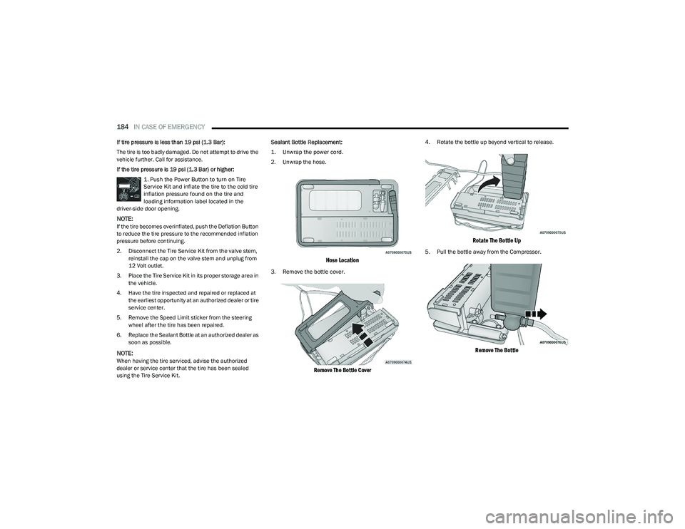
using the Tire Service Kit. Sealant Bottle Replacement:
1. Unwrap the power cord.
2. Unwrap the hose.
Hose Location
3. Remove the bottle cover.
Remove The Bottle Cover
4. Rotate the bottle up beyond vertical to release.
Rotate The Bottle Up
5. Pull the bottle away from the Compressor.
Remove The Bottle
23_RUV_OM_EN_US_t.book Page 184
Page 187 of 256
IN CASE OF EMERGENCY185
NOTE:
For sealant bottle installation, follow these steps in
reverse order.
The Sealant Bottle is a one tire application use and
needs to be replaced after each use. Always replace
these components immediately at your original equip -
ment vehicle dealer.
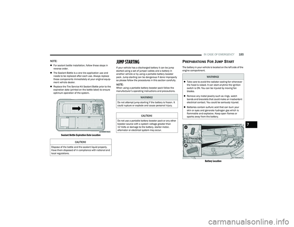
Replace the Tire Service Kit Sealant Bottle prior to the
expiration date (printed on the bottle label) to ensure
optimum operation of the system.
Sealant Bottle Expiration Date Location
JUMP STARTING
If your vehicle has a discharged battery it can be jump
started using a set of jumper cables and a battery in
another vehicle or by using a portable battery booster
pack. Jump starting can be dangerous if done improperly
so please follow the procedures in this section carefully.
NOTE:When using a portable battery booster pack follow the
manufacturer’s operating instructions and precautions.
PREPARATIONS FOR JUMP START
The battery in your vehicle is located on the left side of the
engine compartment.
Battery Location
CAUTION!
Dispose of the bottle and the sealant liquid properly.
Have them disposed of in compliance with national and
local regulations.
WARNING!
Do not attempt jump starting if the battery is frozen. It
could rupture or explode and cause personal injury.
CAUTION!
Do not use a portable battery booster pack or any other
booster source with a system voltage greater than
12 Volts or damage to the battery, starter motor,
alternator or electrical system may occur.
WARNING!
Take care to avoid the radiator cooling fan whenever
the hood is raised. It can start anytime the ignition
switch is ON. You can be injured by moving fan
blades.
Remove any metal jewelry such as rings, watch
bands and bracelets that could make an inadvertent
electrical contact. You could be seriously injured.
Batteries contain sulfuric acid that can burn your
skin or eyes and generate hydrogen gas which is
flammable and explosive. Keep open flames or
sparks away from the battery.
7
23_RUV_OM_EN_US_t.book Page 185
Page 189 of 256
IN CASE OF EMERGENCY187
REFUELING IN EMERGENCY – IF EQUIPPED
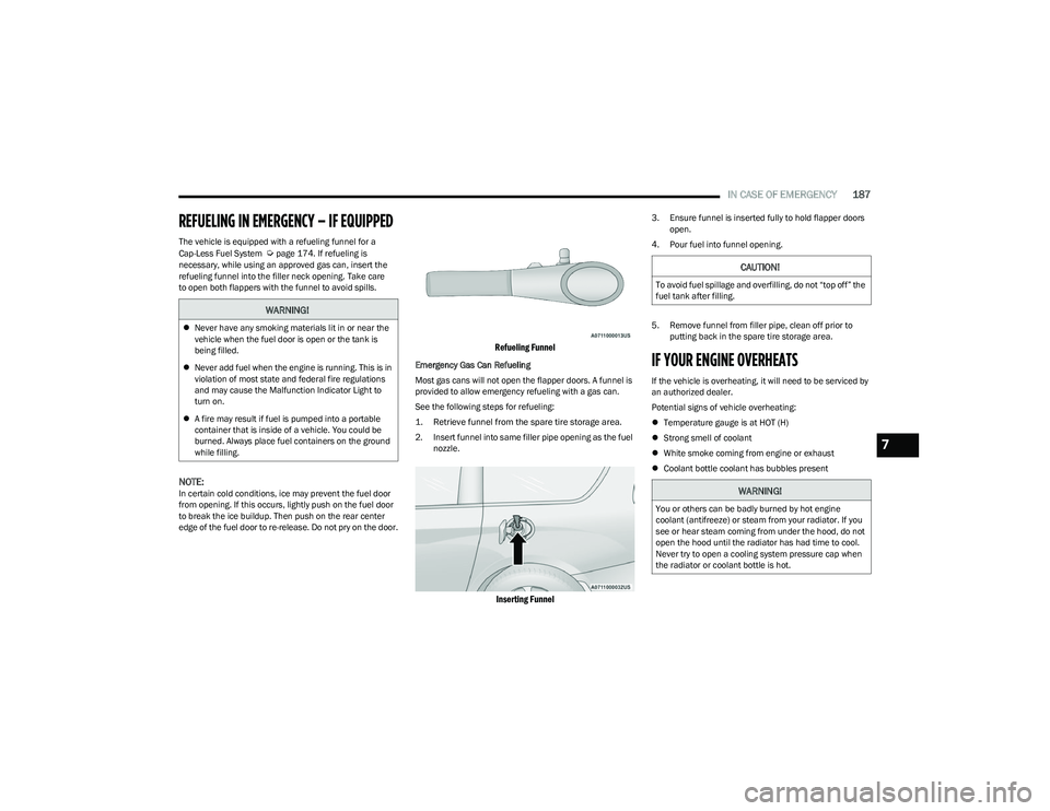
The vehicle is equipped with a refueling funnel for a
Cap-Less Fuel System Úpage 174. If refueling is
necessary, while using an approved gas can, insert the
refueling funnel into the filler neck opening. Take care
to open both flappers with the funnel to avoid spills.
NOTE:In certain cold conditions, ice may prevent the fuel door
from opening. If this occurs, lightly push on the fuel door
to break the ice buildup. Then push on the rear center
edge of the fuel door to re-release. Do not pry on the door.
Refueling Funnel
Emergency Gas Can Refueling
Most gas cans will not open the flapper doors. A funnel is
provided to allow emergency refueling with a gas can.
See the following steps for refueling:
1. Retrieve funnel from the spare tire storage area.
2. Insert funnel into same filler pipe opening as the fuel nozzle.
Inserting Funnel
3. Ensure funnel is inserted fully to hold flapper doors open.
4. Pour fuel into funnel opening.
5. Remove funnel from filler pipe, clean off prior to putting back in the spare tire storage area.
IF YOUR ENGINE OVERHEATS
If the vehicle is overheating, it will need to be serviced by
an authorized dealer.
Potential signs of vehicle overheating:
Temperature gauge is at HOT (H)
Strong smell of coolant
White smoke coming from engine or exhaust
Coolant bottle coolant has bubbles present
WARNING!
Never have any smoking materials lit in or near the
vehicle when the fuel door is open or the tank is
being filled.
Never add fuel when the engine is running. This is in
violation of most state and federal fire regulations
and may cause the Malfunction Indicator Light to
turn on.
A fire may result if fuel is pumped into a portable
container that is inside of a vehicle. You could be
burned. Always place fuel containers on the ground
while filling.
CAUTION!
To avoid fuel spillage and overfilling, do not “top off” the
fuel tank after filling.
WARNING!
You or others can be badly burned by hot engine
coolant (antifreeze) or steam from your radiator. If you
see or hear steam coming from under the hood, do not
open the hood until the radiator has had time to cool.
Never try to open a cooling system pressure cap when
the radiator or coolant bottle is hot.
7
23_RUV_OM_EN_US_t.book Page 187
Page 194 of 256
192
SERVICING AND MAINTENANCE
SCHEDULED SERVICING
Your vehicle is equipped with an automatic oil change
indicator system. The oil change indicator system will
remind you that it is time to take your vehicle in for
scheduled maintenance.
Based on engine operation conditions, the oil change
indicator message will illuminate. This means that service
is required for your vehicle. Operating conditions such as
frequent short-trips, trailer tow, extremely hot or cold
ambient temperatures will influence when the “Oil Change
Required” message is displayed. Have your vehicle
serviced as soon as possible, within the next 500 miles
(805 km).An authorized dealer will reset the oil change indicator
message after completing the scheduled oil change. If a
scheduled oil change is performed by someone other than
an authorized dealer Úpage 62.
NOTE:Under no circumstances should oil change intervals
exceed 10,000 miles (16,000 km), 12 months or
350 hours of engine run time, whichever comes first.
The 350 hours of engine run or idle time is generally
only a concern for fleet customers.
Once A Month Or Before A Long Trip:
Check engine oil level.
Check windshield washer fluid level.
Check tire pressure and look for unusual wear or damage.
Rotate tires at the first sign of irregular wear, even if it
occurs before the oil indicator system turns on.
Check the fluid levels of the coolant reservoir and
brake master cylinder, fill as needed.
Check function of all interior and exterior lights.
23_RUV_OM_EN_US_t.book Page 192
Page 206 of 256
204SERVICING AND MAINTENANCE
Under normal operating conditions, the catalytic converter
will not require maintenance. However, it is important to
keep the engine properly tuned to ensure proper catalyst
operation and prevent possible catalyst damage.
NOTE:Intentional tampering with emissions control systems can
result in civil penalties being assessed against you.
In unusual situations involving grossly malfunctioning
engine operation, a scorching odor may suggest severe
and abnormal catalyst overheating. If this occurs, stop the
vehicle, turn off the engine and allow it to cool. Service,
including a tune-up to the manufacturer specifications,
should be obtained immediately.
To minimize the possibility of catalytic converter damage:
Do not interrupt the ignition when the transmission is
in gear and the vehicle is in motion.
Do not try to start the vehicle by pushing or towing the
vehicle.
Do not idle the engine with any ignition components
disconnected or removed, such as when diagnostic
testing, or for prolonged periods during very rough idle
or malfunctioning operating conditions.
COOLING SYSTEM
Engine Coolant Checks
Check the engine coolant (antifreeze) protection every
12 months (before the onset of freezing weather, where
applicable). If the engine coolant is dirty, the system
should be drained, flushed, and refilled with fresh Organic
Additive Technology (OAT) coolant (conforming to
MS.90032) by an authorized dealer. Check the front of the
A/C condenser for any accumulation of bugs, leaves, etc.
If dirty, clean by gently spraying water from a garden hose
vertically down the face of the condenser. Check the engine cooling system hoses for brittle rubber,
cracking, tears, cuts, and tightness of the connection at
the coolant recovery bottle and radiator. Inspect the entire
system for leaks. DO NOT REMOVE THE COOLANT
PRESSURE CAP WHEN THE COOLING SYSTEM IS HOT.
Cooling System — Drain, Flush And Refill
NOTE:
Some vehicles require special tools to add coolant properly.
Failure to fill these systems properly could lead to severe
internal engine damage. If any coolant is needed to be added
to the system please contact an authorized dealer.
If the engine coolant (antifreeze) is dirty or contains visible
sediment, have an authorized dealer clean and flush with
Organic Additive Technology (OAT) coolant (conforming to
MS.90032).
For the proper maintenance intervals
Úpage 193.
Selection Of Coolant
For further information Úpage 238.
NOTE:
Mixing of engine coolant (antifreeze) other than speci-
fied Organic Additive Technology (OAT) engine coolant,
may result in engine damage and may decrease corro -
sion protection. OAT engine coolant is different and
should not be mixed with Hybrid Organic Additive Tech -
nology (HOAT) engine coolant or any “globally compat -
ible” coolant. If a non-OAT engine coolant is introduced
into the cooling system in an emergency, the cooling
system will need to be drained, flushed, and refilled
with fresh OAT coolant (conforming to MS.90032), by
an authorized dealer as soon as possible.
WARNING!
You or others can be badly burned by hot engine
coolant (antifreeze) or steam from your radiator.
If you see or hear steam coming from under the
hood, do not open the hood until the radiator has had
time to cool. Never open a cooling system pressure
cap when the radiator or coolant bottle is hot.
Keep hands, tools, clothing, and jewelry away from
the radiator cooling fan when the hood is raised.
The fan starts automatically and may start at any
time, whether the engine is running or not.
When working near the radiator cooling fan, discon -
nect the fan motor lead or turn the ignition to the OFF
mode. The fan is temperature controlled and can
start at any time the ignition is in the ON mode.
23_RUV_OM_EN_US_t.book Page 204
Page 219 of 256
SERVICING AND MAINTENANCE217
2. Firmly grab the front side marker lamp socket and
rotate a quarter turn counterclockwise to remove it
from the lamp assembly.
Front Side Marker Lamp Bulb Removal
3. Remove bulb from the front side marker lamp socket and replace with a new bulb.
4. Install front side marker lamp socket in lamp assembly and rotate a quarter turn clockwise to lock
into place.
5. Position the inner wheel liner in place and install the three fasteners.
TIRES
TIRE SAFETY INFORMATION
Tire safety information will cover aspects of the following
information: Tire Markings, Tire Identification Numbers,
Tire Terminology and Definitions, Tire Pressures, and Tire
Loading.
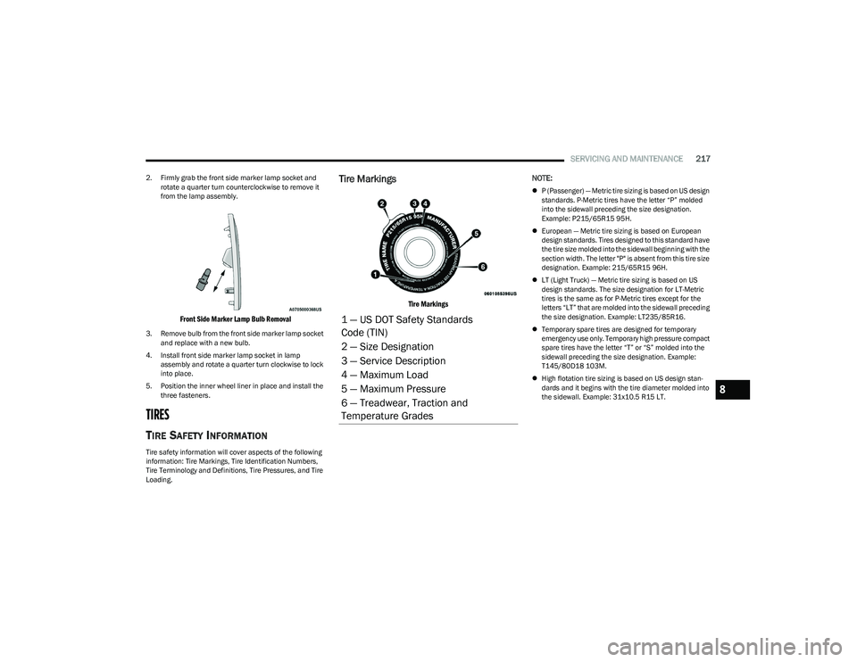
Tire Markings
Tire Markings
NOTE:
P (Passenger) — Metric tire sizing is based on US design
standards. P-Metric tires have the letter “P” molded
into the sidewall preceding the size designation.
Example: P215/65R15 95H.
European — Metric tire sizing is based on European
design standards. Tires designed to this standard have
the tire size molded into the sidewall beginning with the
section width. The letter "P" is absent from this tire size
designation. Example: 215/65R15 96H.
LT (Light Truck) — Metric tire sizing is based on US
design standards. The size designation for LT-Metric
tires is the same as for P-Metric tires except for the
letters “LT” that are molded into the sidewall preceding
the size designation. Example: LT235/85R16.
Temporary spare tires are designed for temporary
emergency use only. Temporary high pressure compact
spare tires have the letter “T” or “S” molded into the
sidewall preceding the size designation. Example:
T145/80D18 103M.
High flotation tire sizing is based on US design stan -
dards and it begins with the tire diameter molded into
the sidewall. Example: 31x10.5 R15 LT.
1 — US DOT Safety Standards
Code (TIN)
2 — Size Designation
3 — Service Description
4 — Maximum Load
5 — Maximum Pressure
6 — Treadwear, Traction and
Temperature Grades
8
23_RUV_OM_EN_US_t.book Page 217
Page 221 of 256
SERVICING AND MAINTENANCE219
Service Description:
95 = Load Index
A numerical code associated with the maximum load a tire can carry
H = Speed Symbol
A symbol indicating the range of speeds at which a tire can carry a load corresponding to its load index under certain operating conditions
The maximum speed corresponding to the speed symbol should only be achieved under specified operating conditions (i.e., tire pressure, vehicle loading, road conditions, and
posted speed limits)
Load Identification:
Absence of the following load identification symbols on the sidewall of the tire indicates a Standard Load (SL) tire:
XL = Extra load (or reinforced) tire, or
LL = Light load tire or
C, D, E, F, G = Load range associated with the maximum load a tire can carry at a specified pressure
Maximum Load – Maximum load indicates the maximum load this tire is designed to carry
Maximum Pressure – Maximum pressure indicates the maximum permissible cold tire inflation pressure for this tire
EXAMPLE:
8
23_RUV_OM_EN_US_t.book Page 219
Page 227 of 256
SERVICING AND MAINTENANCE225
Tire pressures change by approximately 1 psi (7 kPa) per
12°F (7°C) of air temperature change. Keep this in mind
when checking tire pressure inside a garage, especially in
the Winter.
Example: If garage temperature = 68°F (20°C) and the
outside temperature = 32°F (0°C) then the cold tire
inflation pressure should be increased by 3 psi (21 kPa),
which equals 1 psi (7 kPa) for every 12°F (7°C) for this
outside temperature condition.
Tire pressure may increase from 2 to 6 psi (13 to 40 kPa)
during operation. DO NOT reduce this normal pressure
buildup or your tire pressure will be too low.
Tire Pressures For High Speed Operation
The manufacturer advocates driving at safe speeds
and within posted speed limits. Where speed limits or
conditions are such that the vehicle can be driven at high
speeds, maintaining correct tire inflation pressure is very
important. Increased tire pressure and reduced vehicle
loading may be required for high-speed vehicle operation.
Refer to an authorized tire dealer or original equipment
vehicle dealer for recommended safe operating speeds,
loading and cold tire inflation pressures.
Radial Ply Tires
Tire Repair
If your tire becomes damaged, it may be repaired if it
meets the following criteria:
The tire has not been driven on when flat.
The damage is only on the tread section of your tire
(sidewall damage is not repairable).
The puncture is no greater than ¼ of an inch (6 mm).
Consult an authorized tire dealer for tire repairs and
additional information.
Damaged Run Flat tires, or Run Flat tires that have
experienced a loss of pressure should be replaced
immediately with another Run Flat tire of identical size
and service description (Load Index and Speed Symbol).
Replace the tire pressure sensor as well as it is not
designed to be reused.
Run Flat Tires — If Equipped
Run Flat tires allow you the capability to drive 50 miles (80 km)
at 50 mph (80 km/h) after a rapid loss of inflation pressure.
This rapid loss of inflation is referred to as the Run Flat mode.
A Run Flat mode occurs when the tire inflation pressure is of/or
below 14 psi (96 kPa). Once a Run Flat tire reaches the Run Flat
mode it has limited driving capabilities and needs to be
replaced immediately. A Run Flat tire is not repairable. When a
Run Flat tire is changed after being driven in the Run Flat mode
(14 psi [96 kPa] condition), please replace the TPMS sensor as
it is not designed to be reused.
NOTE:TPMS sensor must be replaced after driving the vehicle on
a flat tire condition.
It is not recommended driving a vehicle loaded at full
capacity or to tow a trailer while a tire is in the Run Flat
mode
Úpage 131.
Tire Spinning
When stuck in mud, sand, snow, or ice conditions, do not
spin your vehicle's wheels above 30 mph (48 km/h) or for
longer than 30 seconds continuously without stopping.
WARNING!
High speed driving with your vehicle under maximum
load is dangerous. The added strain on your tires could
cause them to fail. You could have a serious collision.
Do not drive a vehicle loaded to the maximum capacity
at continuous speeds above 75 mph (120 km/h).
WARNING!
Combining radial ply tires with other types of tires on
your vehicle will cause your vehicle to handle poorly.
The instability could cause a collision. Always use radial
ply tires in sets of four. Never combine them with other
types of tires.
WARNING!
Fast spinning tires can be dangerous. Forces generated by
excessive wheel speeds may cause tire damage or failure.
A tire could explode and injure someone. Do not spin your
vehicle's wheels faster than 30 mph (48 km/h) for more
than 30 seconds continuously when you are stuck, and do
not let anyone near a spinning wheel, no matter what the
speed.
8
23_RUV_OM_EN_US_t.book Page 225
Page 228 of 256
226SERVICING AND MAINTENANCE
Tread Wear Indicators
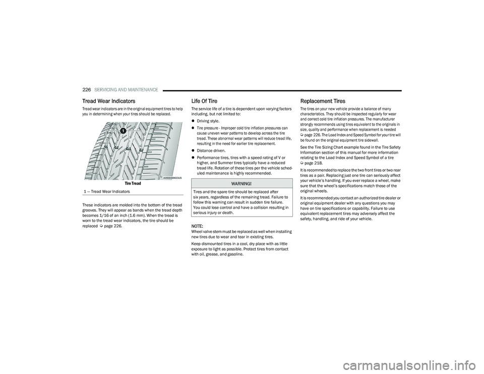
Tread wear indicators are in the original equipment tires to help
you in determining when your tires should be replaced.
Tire Tread
These indicators are molded into the bottom of the tread
grooves. They will appear as bands when the tread depth
becomes 1/16 of an inch (1.6 mm). When the tread is
worn to the tread wear indicators, the tire should be
replaced
Úpage 226.
Life Of Tire
The service life of a tire is dependent upon varying factors
including, but not limited to:
Driving style.
Tire pressure - Improper cold tire inflation pressures can
cause uneven wear patterns to develop across the tire
tread. These abnormal wear patterns will reduce tread life,
resulting in the need for earlier tire replacement.
Distance driven.
Performance tires, tires with a speed rating of V or
higher, and Summer tires typically have a reduced
tread life. Rotation of these tires per the vehicle sched-
uled maintenance is highly recommended.
NOTE:Wheel valve stem must be replaced as well when installing
new tires due to wear and tear in existing tires.
Keep dismounted tires in a cool, dry place with as little
exposure to light as possible. Protect tires from contact
with oil, grease, and gasoline.
Replacement Tires
The tires on your new vehicle provide a balance of many
characteristics. They should be inspected regularly for wear
and correct cold tire inflation pressures. The manufacturer
strongly recommends using tires equivalent to the originals in
size, quality and performance when replacement is needed
Ú
page 226. The Load Index and Speed Symbol for your tire will
be found on the original equipment tire sidewall.
See the Tire Sizing Chart example found in the Tire Safety
Information section of this manual for more information
relating to the Load Index and Speed Symbol of a tire
Úpage 218.
It is recommended to replace the two front tires or two rear
tires as a pair. Replacing just one tire can seriously affect
your vehicle’s handling. If you ever replace a wheel, make
sure that the wheel’s specifications match those of the
original wheels.
It is recommended you contact an authorized tire dealer or
original equipment dealer with any questions you may
have on tire specifications or capability. Failure to use
equivalent replacement tires may adversely affect the
safety, handling, and ride of your vehicle.
1 — Tread Wear Indicators
WARNING!
Tires and the spare tire should be replaced after
six years, regardless of the remaining tread. Failure to
follow this warning can result in sudden tire failure.
You could lose control and have a collision resulting in
serious injury or death.
23_RUV_OM_EN_US_t.book Page 226