instrument cluster CHRYSLER VOYAGER 2023 Owners Manual
[x] Cancel search | Manufacturer: CHRYSLER, Model Year: 2023, Model line: VOYAGER, Model: CHRYSLER VOYAGER 2023Pages: 256, PDF Size: 13.97 MB
Page 5 of 256
3
GETTING TO KNOW YOUR
INSTRUMENT PANEL
BASE INSTRUMENT CLUSTER ...........................................59Base Instrument Cluster Descriptions....................... 60
PREMIUM INSTRUMENT CLUSTER ...................................61 Premium Instrument Cluster Descriptions ................ 62
INSTRUMENT CLUSTER DISPLAY ....................................62 Instrument Cluster Display Location And Controls ... 62
Oil Life Reset ............................................................... 63
KeySense Cluster Messages —
If Equipped .................................................................. 64
Instrument Cluster Display Menu Items ................... 64
Battery Saver On/Battery Saver Mode Message —
Electrical Load Reduction Actions — If Equipped ..... 66
WARNING LIGHTS AND MESSAGES.................................67 Red Warning Lights ..................................................... 67
Yellow Warning Lights ................................................. 70
Yellow Indicator Lights ................................................ 72
Green Indicator Lights ................................................ 72
White Indicator Lights ................................................. 72
Blue Indicator Lights ................................................... 73
ONBOARD DIAGNOSTIC SYSTEM — OBD II .....................73 Onboard Diagnostic System
(OBD II) Cybersecurity ................................................. 73
EMISSIONS INSPECTION AND MAINTENANCE
PROGRAMS ........................................................................74
STARTING AND OPERATING
STARTING THE ENGINE ...................................................... 75 Normal Starting ........................................................... 75
AutoPark .......................................................................75
Cold Weather Operation
(Below –22°F Or −30°C) ........................................... 77
After Starting — Warming Up The Engine ................... 77
If Engine Fails To Start ............................................... 77
To Turn Off The Engine Using ENGINE START/STOP
Button ........................................................................... 78
ENGINE BLOCK HEATER — IF EQUIPPED ........................ 78
ENGINE BREAK-IN RECOMMENDATIONS ....................... 78
PARKING BRAKE ................................................................ 79 Electric Park Brake (EPB) ........................................... 79
AUTOMATIC TRANSMISSION ............................................ 81 Ignition Park Interlock ................................................. 81
Brake/Transmission Shift Interlock (BTSI) System ... 82
9-Speed Automatic Transmission ..............................82
Gear Ranges ................................................................ 82
ACTIVE NOISE CANCELLATION ......................................... 84
POWER STEERING .............................................................. 84
STOP/START SYSTEM — IF EQUIPPED ............................ 85 Autostop Mode............................................................. 85
Possible Reasons The Engine Does Not Autostop .... 85
To Start The Engine While In Auto Stop/Start ........... 85
To Manually Turn Off The Stop/Start System ............ 86
To Manually Turn On The Stop/Start System ............ 86
System Malfunction..................................................... 86
CRUISE CONTROL SYSTEMS — IF EQUIPPED ................. 86 Cruise Control .............................................................. 86 PARKSENSE REAR PARK ASSIST —
IF EQUIPPED ...................................................................... 87
ParkSense Sensors ..................................................... 88
ParkSense Warning Display........................................ 88
ParkSense Display ...................................................... 88
Enabling And Disabling ParkSense ............................ 91
Service The ParkSense Rear Park Assist System ..... 91
Cleaning The ParkSense System ............................... 91
ParkSense System Usage Precautions ...................... 91
PARKVIEW REAR BACK UP CAMERA ............................. 92
REFUELING THE VEHICLE .................................................. 93
VEHICLE LOADING ............................................................. 93 Certification Label ....................................................... 93
TRAILER TOWING ............................................................... 94 Common Towing Definitions....................................... 94
Trailer Hitch Classification .......................................... 96
Trailer Towing Weights (Maximum Trailer Weight
Ratings) ....................................................................... 97
Vehicle Loading Chart ................................................. 97
Trailer And Tongue Weight ......................................... 99
Towing Requirements ................................................ 99
Towing Tips ............................................................... 101
RECREATIONAL TOWING (BEHIND MOTORHOME) ..... 101 Towing This Vehicle Behind Another Vehicle ........... 101
DRIVING TIPS ....................................................................102 Driving On Slippery Surfaces .................................... 102
Driving Through Water ............................................. 103
23_RUV_OM_EN_US_t.book Page 3
Page 12 of 256
10
GETTING TO KNOW YOUR VEHICLE
KEYS
KEY FOB
Your vehicle is equipped with a key fob which supports Passive
Entry, Remote Keyless Entry (RKE), Keyless Enter ‘n Go™
(if equipped), and Remote Start (if equipped). The key fob
allows you to lock or unlock all doors and liftgate, as well as
activate the Panic Alarm from distances up to approximately
66 ft (20 m). The key fob does not need to be pointed at the
vehicle to activate the system. The key fob also contains an
emergency key, which is stored in the rear of the key fob.
The emergency key allows for entry into the vehicle should
the battery in the vehicle or the key fob become depleted.
The emergency key is also for locking/unlocking the glove
compartment. You can keep the emergency key with you
when valet parking.
NOTE:
The key fob’s wireless signal may be blocked if the key
fob is located next to a mobile phone, laptop, or other
electronic device. This may result in poor performance.
A low key fob battery condition may be indicated by a
message in the instrument cluster display, or by the
LED light on the key fob. If the LED key fob light no
longer illuminates from key fob button pushes, then
the key fob battery requires replacement.
The key fob LED light brightness is designed for indoor
light viewing, so the LED light may not be visible in
direct sunlight
Úpage 244.
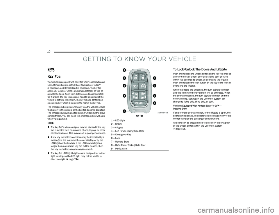
Key Fob
To Lock/Unlock The Doors And Liftgate
Push and release the unlock button on the key fob once to
unlock the driver’s front door and sliding door or twice
within five seconds to unlock all doors and the liftgate.
Push and release the lock button on the key fob to lock all
doors and the liftgate.
When the doors are unlocked, the turn signals will flash
and the illuminated entry system will be activated. When
the doors are locked, the turn signals will flash and the
horn will chirp. Settings in the Uconnect system can
change to lights only, chirp only, or both.
Vehicles Equipped With Keyless Enter ‘n Go™ —
Passive Entry
If one or more doors are open, or the liftgate is open, the
doors can be locked. The doors will unlock again only if the
key fob is inside the passenger compartment.
All doors can be programmed to unlock on the first push
of the unlock button within the Uconnect system
Úpage 105.
1 — LED Light
2 — Unlock
3 — Liftgate
4 — Left Power Sliding Side Door
5 — Emergency Key
6 — Lock
7 — Remote Start
8 — Right Power Sliding Side Door
9 — Panic Alarm
23_RUV_OM_EN_US_t.book Page 10
Page 13 of 256
GETTING TO KNOW YOUR VEHICLE11
Key Left Vehicle Feature
If a valid key fob is no longer detected inside the vehicle
while the vehicle’s ignition system is in the ON/RUN or
START position, the message “Key Fob Has Left The
Vehicle” will be shown in the instrument cluster display
along with an interior chime. An exterior audible and visual
alert will also be activated to warn the driver.
The vehicle’s horn will rapidly chirp three times along with
a single flash of the vehicle’s exterior lights.
NOTE:
The doors have to be open and then closed in order for
the vehicle to check for the presence of a key fob; the
Key Left Vehicle feature will not activate until all of the
doors are closed.
These alerts will not be activated in situations where
the vehicle’s engine is left running with the key fob
inside.
Replacing The Battery In The Key Fob
The recommended replacement battery is one CR2032
battery.
NOTE:
Customers are recommended to use a battery
obtained from Mopar®. Aftermarket coin battery
dimensions may not meet the original OEM coin battery
dimensions.
Batteries contain harmful chemicals. Dispose old
batteries by placing them in correct containers
according to the law or by taking them to a dealership,
where they will be handled appropriately.
Perchlorate Material — special handling may apply.
See www.dtsc.ca.gov/hazardouswaste/perchlorate for
further information.
Do not touch the battery terminals that are on the back
housing or the printed circuit board.
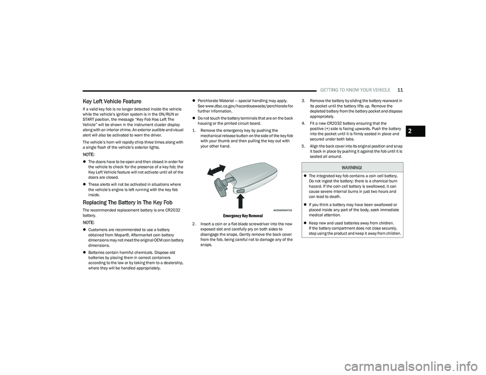
1. Remove the emergency key by pushing the mechanical release button on the side of the key fob
with your thumb and then pulling the key out with
your other hand.
Emergency Key Removal
2. Insert a coin or a flat-blade screwdriver into the now exposed slot and carefully pry on both sides to
disengage the snaps. Gently remove the back cover
from the fob, being careful not to damage any of the
snaps. 3. Remove the battery by sliding the battery rearward in
its pocket until the battery lifts up. Remove the
depleted battery from the battery pocket and dispose
appropriately.
4. Fit a new CR2032 battery ensuring that the positive (+) side is facing upwards. Push the battery
into the pocket until it is firmly seated in place and
secured under both tabs.
5. Align the back cover into its original position and snap it back in place by pushing it against the fob until it is
seated all around.
WARNING!
The integrated key fob contains a coin cell battery.
Do not ingest the battery; there is a chemical burn
hazard. If the coin cell battery is swallowed, it can
cause severe internal burns in just two hours and
can lead to death.
If you think a battery may have been swallowed or
placed inside any part of the body, seek immediate
medical attention.
Keep new and used batteries away from children.
If the battery compartment does not close securely,
stop using the product and keep it away from children.
2
23_RUV_OM_EN_US_t.book Page 11
Page 17 of 256
GETTING TO KNOW YOUR VEHICLE15
NOTE:
For vehicles equipped with the Keyless Enter ‘n Go™ —
Passive Entry feature, the message “Remote Start
Active — Push Start Button” will show in the instrument
cluster display until you push the START/STOP ignition
button.
To avoid unintentional shutdowns, the system will
disable for two seconds after receiving a valid Remote
Start request.
REMOTE START FRONT DEFROST
A
CTIVATION — IF EQUIPPED
When Remote Start is active, and the outside ambient
temperature is 40°F (4.5°C) or below, the system will
automatically activate front defrost for 15 minutes or less.
The time is dependent on the ambient temperature. Once
the timer expires, the system will automatically adjust the
settings depending on ambient conditions. See “Remote
Start Comfort Systems — If Equipped” in the next section
for detailed operation.
REMOTE START COMFORT SYSTEMS —
I
F EQUIPPED
When Remote Start is activated, the front and rear defrost
will automatically turn on in cold weather. The heated
steering wheel and driver heated seat feature will also
turn on if programmed in the comfort menu screen within
Uconnect Settings
Úpage 105. In warm weather, the
driver vented seat feature will automatically turn on when
the Remote Start is activated, if programmed via the comfort menu screen. The vehicle will adjust the climate
control settings depending on the outside ambient
temperature.
Automatic Temperature Control (ATC) — If Equipped
The climate controls automatically adjust to an optimal
temperature and mode, dependent upon the outside
ambient temperature. When the ignition is placed in the
ON/RUN position, the climate controls will resume their
previous settings.
Manual Temperature Control (MTC) — If Equipped
In ambient temperatures of 40°F (4.5°C) or below, the
climate settings will default to maximum heat, with
fresh air entering the cabin. If the front defrost timer
expires, the vehicle will enter Mix Mode.
In ambient temperatures from 40°F (4.5°C) to 78°F
(26°C), the climate settings will be based on the last
settings selected by the driver.
In ambient temperatures of 78°F (26°C) or above, the
climate settings will default to MAX A/C, Bi-Level mode,
and Recirculation on.
For more information on ATC, MTC, and climate control
settings, see
Úpage 44.
NOTE:
These features will stay on through the duration of Remote
Start until the ignition is placed in the ON/RUN position.
The climate control settings will change, and exit automatic
operation, if manually adjusted by the driver while the vehicle is
in Remote Start mode. This includes the OFF button on the
climate controls, which will turn the system off.
REMOTE START WINDSHIELD WIPER
D
E-ICER ACTIVATION — IF EQUIPPED
When the Remote Start system is active and the outside
ambient temperature is less than 33°F (0.6°C), the
Windshield Wiper De-Icer will activate. Exiting Remote
Start will resume its previous operation. If the Windshield
Wiper De-Icer was active, the timer and operation will
continue.
REMOTE START CANCEL MESSAGE
One of the following messages will display in the
instrument cluster if the vehicle fails to remote start or
exits Remote Start prematurely:
Remote Start Canceled — Door Open
Remote Start Canceled — Hood Open
Remote Start Canceled — Fuel Low
Remote Start Canceled — Liftgate Open
Remote Start Canceled — Too Cold
Remote Start Canceled — Time Expired
Remote Start Disabled — Start Vehicle To Reset
The message will stay active until the ignition is placed in
the ON/RUN position.
2
23_RUV_OM_EN_US_t.book Page 15
Page 18 of 256
16GETTING TO KNOW YOUR VEHICLE
VEHICLE SECURITY SYSTEM — IF EQUIPPED
The Vehicle Security system monitors the vehicle doors for
unauthorized entry and the ignition switch for unauthorized
operation. When the alarm is activated, the interior switches for
door locks, power sliding doors and power liftgate are disabled.
The Vehicle Security system provides both audible and visible
signals. If something triggers the alarm, the Vehicle Security
system will provide the following audible and visible signals: the
horn will pulse, the parking lights and/or turn signals will flash,
and the Vehicle Security Light in the instrument cluster will
flash.
TO ARM THE SYSTEM
Follow these steps to arm the Vehicle Security system:
1. Make sure the vehicle’s ignition is placed in the OFF
position.
For vehicles equipped with Keyless Enter ‘n Go™ —
Passive Entry, make sure the vehicle ignition
system is OFF.
2. Perform one of the following methods to lock the vehicle:
Push lock on the interior power door lock switch
with the driver and/or passenger door open.
Push the lock button on the exterior Passive Entry
door handle with a valid key fob available in the
same exterior zone
Úpage 18.
Push the lock button on the key fob.
3. If any doors are open, close them.
TO DISARM THE SYSTEM
The Vehicle Security system can be disarmed using any of
the following methods:
Push the unlock button on the key fob.
Grab the Passive Entry door handle (if equipped)
Úpage 18.
Cycle the vehicle ignition system out of the OFF position.
For vehicles equipped with Keyless Enter ‘n Go™ —
Passive Entry, push the keyless ignition START/STOP
ignition button (requires at least one valid key fob in
the vehicle).
NOTE:
The driver's door key cylinder and the liftgate button on
the key fob cannot arm or disarm the Vehicle Security
system.
The Vehicle Security system remains armed during
power liftgate entry. Pushing the liftgate button will not
disarm the Vehicle Security system. If someone enters
the vehicle through the opened liftgate, then opens any
door, the alarm will sound.
When the Vehicle Security system is armed, the interior
power door lock switches will not unlock the doors.
The Vehicle Security system is designed to protect your
vehicle. However, you can create conditions where the
system will give you a false alarm. If one of the previously
described arming sequences has occurred, the Vehicle
Security system will arm regardless of whether you are in the vehicle or not. If you remain in the vehicle and open a
door, the alarm will sound. If this occurs, disarm the
Vehicle Security system.
If the Vehicle Security system is armed and the battery
becomes disconnected, the Vehicle Security system will
remain armed when the battery is reconnected; the
exterior lights will flash, and the horn will sound. If this
occurs, disarm the Vehicle Security system.
REARMING OF THE SYSTEM
If something triggers the alarm and no action is taken to
disarm it, the Vehicle Security system will turn the horn off
after a 29 second cycle (with five seconds between cycles
and up to eight cycles if the trigger remains active) and
then rearm itself.
SECURITY SYSTEM MANUAL OVERRIDE
The Vehicle Security system will not arm if you lock the
doors using the manual door lock.
DOORS
MANUAL DOOR LOCKS
To lock each door, rotate the door lock knob on each door
trim panel forward. To unlock the front doors, pull the
inside door handle to the first detent or rotate the door
lock button until the ribbing is visible. To unlock the rear
doors, rotate the door lock button until the red indicator is
visible.
23_RUV_OM_EN_US_t.book Page 16
Page 23 of 256
GETTING TO KNOW YOUR VEHICLE21
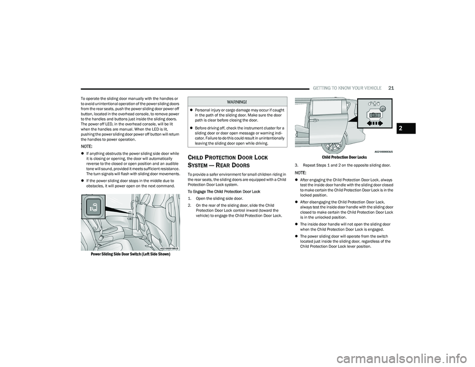
To operate the sliding door manually with the handles or
to avoid unintentional operation of the power sliding doors
from the rear seats, push the power sliding door power off
button, located in the overhead console, to remove power
to the handles and buttons just inside the sliding doors.
The power off LED, in the overhead console, will be lit
when the handles are manual. When the LED is lit,
pushing the power sliding door power off button will return
the handles to power operation.
NOTE:
If anything obstructs the power sliding side door while
it is closing or opening, the door will automatically
reverse to the closed or open position and an audible
tone will sound, provided it meets sufficient resistance.
The turn signals will flash with sliding door movements.
If the power sliding door stops in the middle due to
obstacles, it will power open on the next command.
Power Sliding Side Door Switch (Left Side Shown)
CHILD PROTECTION DOOR LOCK
S
YSTEM — REAR DOORS
To provide a safer environment for small children riding in
the rear seats, the sliding doors are equipped with a Child
Protection Door Lock system.
To Engage The Child Protection Door Lock
1. Open the sliding side door.
2. On the rear of the sliding door, slide the Child
Protection Door Lock control inward (toward the
vehicle) to engage the Child Protection Door Lock.
Child Protection Door Locks
3. Repeat Steps 1 and 2 on the opposite sliding door.
NOTE:
After engaging the Child Protection Door Lock, always
test the inside door handle with the sliding door closed
to make certain the Child Protection Door Lock is in the
locked position.
After disengaging the Child Protection Door Lock,
always test the inside door handle with the sliding door
closed to make certain the Child Protection Door Lock
is in the unlocked position.
The inside door handle will not open the sliding door
when the Child Protection Door Lock is engaged.
The power sliding door will operate from the switch
located just inside the sliding door, regardless of the
Child Protection Door Lock lever position.
WARNING!
Personal injury or cargo damage may occur if caught
in the path of the sliding door. Make sure the door
path is clear before closing the door.
Before driving off, check the instrument cluster for a
sliding door or door open message or warning indi -
cator. Failure to do this could result in unintentionally
leaving the sliding door open while driving.
2
23_RUV_OM_EN_US_t.book Page 21
Page 43 of 256
GETTING TO KNOW YOUR VEHICLE41
HEADLIGHT TIME DELAY — IF EQUIPPED
This feature provides the safety of headlight illumination
for up to 90 seconds after exiting your vehicle.
To activate the delay feature, place the ignition in the OFF
position while the headlights are still on. The 90 second
delay interval begins when headlight switch is turned off.
If the headlights or parking lights are turned back on or the
ignition is placed in the ON position, the delay will be
canceled.
When exiting the vehicle the driver can choose to have the
headlights remain on for 30, 60, or 90 seconds or not
remain on. You can change the timer setting through the
Uconnect system
Úpage 105.
If the headlights are turned off before the ignition, they will
turn off in the normal manner.
NOTE:The headlights must be turned off within 45 seconds of
placing the ignition in the OFF position to activate this
feature.
LIGHTS-ON REMINDER
If the headlights or the parking lights are left on after the
ignition is placed in the OFF position, the vehicle will chime
when the driver's door is opened.
TURN SIGNALS
Move the multifunction lever up or down to activate the
turn signals. The arrows on each side of the instrument
cluster flash to show proper operation.
NOTE:If either light remains on and does not flash, or there is a
very fast flash rate, check for a defective outside light
bulb.
Turn Signal Warning
If the vehicle electronics sense that the vehicle has
traveled for about 1 mile (1.6 km) with a turn signal on, a
chime will sound and a message will display in the cluster
to alert the driver.
LANE CHANGE ASSIST — IF EQUIPPED
Tap the multifunction lever up or down once, without
moving beyond the detent, and the turn signal (right or
left) will flash three times then automatically turn off.
BATTERY PROTECTION
This feature provides battery protection to avoid wearing down
the battery if the headlights or parking lights are left on for
extended periods of time when the ignition is in the OFF
position. After eight minutes of the ignition being in the OFF
position and the headlight switch in any position other than OFF
or AUTO, the lights will turn off automatically until the next cycle
of the ignition or headlight switch.
The battery protection feature will be disabled if the
ignition is placed in any position other than OFF during the
eight minute delay.
INTERIOR LIGHTS
INTERIOR COURTESY LIGHTS
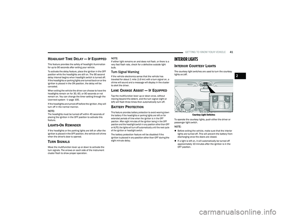
The courtesy light switches are used to turn the courtesy
lights on/off.
Courtesy Light Switches
To operate the courtesy lights, push either the driver or
passenger light switch.
NOTE:
Before exiting the vehicle, make sure that the interior
lights are turned off. This will prevent the battery from
discharging once the doors are closed.
If a light is left on, it will automatically be turned off
approximately 10 minutes after the ignition is in the
OFF position.
2
23_RUV_OM_EN_US_t.book Page 41
Page 44 of 256
42GETTING TO KNOW YOUR VEHICLE
Rear Courtesy/Reading Lights —
If Equipped
Located above the rear passengers are courtesy/reading
lights. The lights turn on when a front door, a sliding door
or the liftgate is opened. If your vehicle is equipped with
Remote Keyless Entry (RKE) the lights will also turn on
when the unlock button on the key fob is pushed.
The courtesy lights also function as reading lights. Push
the lens to turn these lights on while inside the vehicle.
Push the lens a second time to turn each light off.
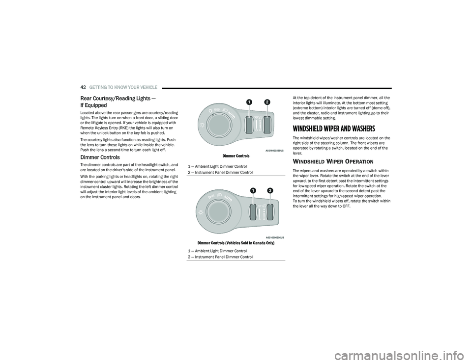
Dimmer Controls
The dimmer controls are part of the headlight switch, and
are located on the driver’s side of the instrument panel.
With the parking lights or headlights on, rotating the right
dimmer control upward will increase the brightness of the
instrument cluster lights. Rotating the left dimmer control
will adjust the interior light levels of the ambient lighting
on the instrument panel and doors.
Dimmer Controls
Dimmer Controls (Vehicles Sold In Canada Only)
At the top detent of the instrument panel dimmer, all the
interior lights will illuminate. At the bottom most setting
(extreme bottom) interior lights are turned off (dome off),
and the cluster, radio and instrument lighting go to their
lowest dimmable setting.
WINDSHIELD WIPER AND WASHERS
The windshield wiper/washer controls are located on the
right side of the steering column. The front wipers are
operated by rotating a switch, located on the end of the
lever.
WINDSHIELD WIPER OPERATION
The wipers and washers are operated by a switch within
the wiper lever. Rotate the switch at the end of the lever
upward, to the first detent past the intermittent settings
for low-speed wiper operation. Rotate the switch at the
end of the lever upward to the second detent past the
intermittent settings for high-speed wiper operation.
To turn the windshield wipers off, rotate the switch within
the lever all the way down to OFF.
1 — Ambient Light Dimmer Control
2 — Instrument Panel Dimmer Control
1 — Ambient Light Dimmer Control
2 — Instrument Panel Dimmer Control
23_RUV_OM_EN_US_t.book Page 42
Page 61 of 256
59
GETTING TO KNOW YOUR INSTRUMENT PANEL
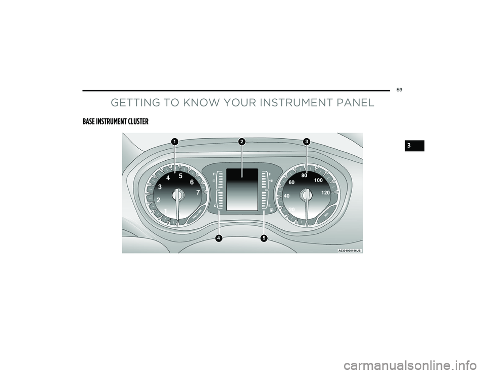
BASE INSTRUMENT CLUSTER
3
23_RUV_OM_EN_US_t.book Page 59
Page 62 of 256
60GETTING TO KNOW YOUR INSTRUMENT PANEL
BASE INSTRUMENT CLUSTER
D
ESCRIPTIONS
Use this QR code to access your digital
experience.
1. Tachometer
Indicates the engine speed
in revolutions per minute
(RPM x 1000).
2. Instrument Cluster Display When the appropriate conditions exist, this display
shows the instrument cluster display messages
Úpage 62.
3. Speedometer Indicates vehicle speed.
4. Temperature Gauge The temperature gauge shows engine coolant
temperature. Any reading within the normal range
indicates that the engine cooling system is oper -
ating satisfactorily.
The gauge can indicate a higher temperature
when driving in hot weather or up mountain
grades. It should not be allowed to exceed the
upper limits of the normal operating range. 5. Fuel Gauge
The gauge shows the level of fuel in the fuel tank when
the ignition switch is in the ON/RUN position.
The fuel pump symbol points to the side
of the vehicle where the fuel door is
located.
NOTE:The warning/indicator lights will illuminate for a bulb
check when the ignition is first cycled.
WARNING!
A hot engine cooling system is dangerous. You or others
could be badly burned by steam or boiling coolant. You
may want to call an authorized dealer for service if your
vehicle overheats
Úpage 204.
CAUTION!
Driving with a hot engine cooling system could damage
your vehicle. If the temperature gauge reaches “H” pull
over and stop the vehicle. Idle the vehicle with the air
conditioner turned off until the gauge drops back into
the normal range and is no longer red. If the gauge
remains on the “H”, turn the engine off immediately
and call an authorized dealer for service.
23_RUV_OM_EN_US_t.book Page 60